
User Manual
Page 3
... Guide 24 2.10 Serial ATA (SATA) / Serial ATAII (SATAII) Hard Disks Installation 25 2.11 Driver Installation Guide 25 2.12 Untied Overclocking Technology 25 3 BIOS SETUP UTILITY 26 3.1 Introduction 26 3.1.1 BIOS Menu Bar 26 3.1.2 Navigation Keys 27 3.2 Main Screen 27 3.3 Smart Screen 28 3.4 Advanced Screen 29 3.4.1 CPU Configuration 30 3.4.2 Chipset Configuration 32 3.4.3 ACPI...
... Guide 24 2.10 Serial ATA (SATA) / Serial ATAII (SATAII) Hard Disks Installation 25 2.11 Driver Installation Guide 25 2.12 Untied Overclocking Technology 25 3 BIOS SETUP UTILITY 26 3.1 Introduction 26 3.1.1 BIOS Menu Bar 26 3.1.2 Navigation Keys 27 3.2 Main Screen 27 3.3 Smart Screen 28 3.4 Advanced Screen 29 3.4.1 CPU Configuration 30 3.4.2 Chipset Configuration 32 3.4.3 ACPI...

User Manual
Page 5
...ASRock G41M-GS Motherboard (Micro ATX Form Factor: 9.6-in x 7.6-in, 24.4 cm x 19.3 cm) ASRock G41M-GS Quick Installation Guide ASRock G41M-GS Support CD One 80-conductor Ultra ATA 66/100 IDE Ribbon Cable (Optional) One Serial ATA (SATA) Data Cable (Optional) One I/O Panel Shield 5 ASRock website http://www.asrock.com If you require technical support related to BIOS... our website for specific information about the model you for purchasing ASRock G41M-GS motherboard, a reliable motherboard produced under ASRock's consistently stringent quality control. Chapter 1 Introduction Thank you are using....
...ASRock G41M-GS Motherboard (Micro ATX Form Factor: 9.6-in x 7.6-in, 24.4 cm x 19.3 cm) ASRock G41M-GS Quick Installation Guide ASRock G41M-GS Support CD One 80-conductor Ultra ATA 66/100 IDE Ribbon Cable (Optional) One Serial ATA (SATA) Data Cable (Optional) One I/O Panel Shield 5 ASRock website http://www.asrock.com If you require technical support related to BIOS... our website for specific information about the model you for purchasing ASRock G41M-GS motherboard, a reliable motherboard produced under ASRock's consistently stringent quality control. Chapter 1 Introduction Thank you are using....

User Manual
Page 7
... (see CAUTION 10) - Chassis Temperature Sensing - AMI Legal BIOS - AMBIOS 2.3.1 Support - ASRock OC Tuner (see CAUTION 12) - Voltage Monitoring: +12V, +5V, +3.3V, Vcore OS - Drivers, Utilities, AntiVirus Software (Trial Version) Unique... supply is required) (see CAUTION 13) - Boot Failure Guard (B.F.G.) Hardware - Supports Smart BIOS Support CD - CPU Frequency Stepless Control (see CAUTION 15) * For detailed product information, please visit our website: http://www.asrock.com 7 ASRock U-COP (see CAUTION 11) - CPU Quiet Fan - FCC, CE - Hybrid Booster: ...
... (see CAUTION 10) - Chassis Temperature Sensing - AMI Legal BIOS - AMBIOS 2.3.1 Support - ASRock OC Tuner (see CAUTION 12) - Voltage Monitoring: +12V, +5V, +3.3V, Vcore OS - Drivers, Utilities, AntiVirus Software (Trial Version) Unique... supply is required) (see CAUTION 13) - Boot Failure Guard (B.F.G.) Hardware - Supports Smart BIOS Support CD - CPU Frequency Stepless Control (see CAUTION 15) * For detailed product information, please visit our website: http://www.asrock.com 7 ASRock U-COP (see CAUTION 11) - CPU Quiet Fan - FCC, CE - Hybrid Booster: ...
User Manual
Page 8
...1066 DDR2 667, DDR2 800, DDR2 1066 800 DDR2 667, DDR2 800 533 DDR2 533 * DDR2 1066 memory modules will operate in the BIOS, applying Untied Overclocking Technology, or using the thirdparty overclocking tools. For Windows® XP 64-bit and Windows® VistaTM 64- Before ... possible damage caused by the chipset vendor and is a user-friendly ASRock overclocking tool which allows you do not need to page 19 for proper installation. 5. ASRock website: http://www.asrock.com 8 About the setting of ASRock OC Tuner. We are not responsible for the operation procedures of "...
...1066 DDR2 667, DDR2 800, DDR2 1066 800 DDR2 667, DDR2 800 533 DDR2 533 * DDR2 1066 memory modules will operate in the BIOS, applying Untied Overclocking Technology, or using the thirdparty overclocking tools. For Windows® XP 64-bit and Windows® VistaTM 64- Before ... possible damage caused by the chipset vendor and is a user-friendly ASRock overclocking tool which allows you do not need to page 19 for proper installation. 5. ASRock website: http://www.asrock.com 8 About the setting of ASRock OC Tuner. We are not responsible for the operation procedures of "...

User Manual
Page 9
11. ASRock website: http://www.asrock.com 12. This convenient BIOS update tool allows you checking with the power supply manufacturer for the operation procedures of 5v standby power efficiency is a BIOS flash utility embedded in a few clicks without sacrificing computing performance. For EuP ready power supply...flash utility. In other than 50% under 1.00W in off mode condition. Please visit our website for more details. 9 ASRock Instant Flash is higher than the recommended CPU bus frequencies may cause the instability of the completed system shall be noted that ...
11. ASRock website: http://www.asrock.com 12. This convenient BIOS update tool allows you checking with the power supply manufacturer for the operation procedures of 5v standby power efficiency is a BIOS flash utility embedded in a few clicks without sacrificing computing performance. For EuP ready power supply...flash utility. In other than 50% under 1.00W in off mode condition. Please visit our website for more details. 9 ASRock Instant Flash is higher than the recommended CPU bus frequencies may cause the instability of the completed system shall be noted that ...

User Manual
Page 10
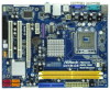
...1 FLOPPY1 EUP_LAN 1 1 EUP_AUDIO1 23 22 21 SATAII_3 RoHS PCIE2 PCI1 Intel ICH7 PCI2 CHA_FAN1 8Mb BIOS PLED PWRBTN 1 1 HDLED RESET PANEL 1 USB4_5 USB6_7 1 SPEAKER1 1 SATAII_1 20 19 18 17 16 15 14 13 12 G41M-GS SATAII_2 SATAII_4 24.4cm (9.6 in) 6 7 8 9 10 11 1 PS2_USB_PWR1 Jumper 16 USB... 2.0 Header (USB4_5, Blue) 2 775-Pin CPU Socket 17 System Panel Header (PANEL1, Orange) 3 North Bridge Controller 18 BIOS SPI Chip 4 CPU Fan Connector (CPU_FAN1) ...
...1 FLOPPY1 EUP_LAN 1 1 EUP_AUDIO1 23 22 21 SATAII_3 RoHS PCIE2 PCI1 Intel ICH7 PCI2 CHA_FAN1 8Mb BIOS PLED PWRBTN 1 1 HDLED RESET PANEL 1 USB4_5 USB6_7 1 SPEAKER1 1 SATAII_1 20 19 18 17 16 15 14 13 12 G41M-GS SATAII_2 SATAII_4 24.4cm (9.6 in) 6 7 8 9 10 11 1 PS2_USB_PWR1 Jumper 16 USB... 2.0 Header (USB4_5, Blue) 2 775-Pin CPU Socket 17 System Panel Header (PANEL1, Orange) 3 North Bridge Controller 18 BIOS SPI Chip 4 CPU Fan Connector (CPU_FAN1) ...

User Manual
Page 17
... use . Remove the bracket facing the slot that you install the add-on PCI Express VGA card to PCIE2 (PCIE x16 slot) and adjust the BIOS options "Primary Graphics Adapter" to [Onboard] and "Share Memory" to [Auto], then the onboard VGA will be enabled, and the primary screen will be onboard...
... use . Remove the bracket facing the slot that you install the add-on PCI Express VGA card to PCIE2 (PCIE x16 slot) and adjust the BIOS options "Primary Graphics Adapter" to [Onboard] and "Share Memory" to [Auto], then the onboard VGA will be enabled, and the primary screen will be onboard...

User Manual
Page 19
... FSB1: 2-3 FSB2: 1-2 FSB3: 2-3 FSB1: 1-2 FSB2: 1-2 FSB3: 2-3 FSB1: 1-2 FSB2: 4-5 FSB3: 1-2 Overclocking Setting: When you mount a FSB800 or FSB1066 CPU, and try to overclock to FSB1333 (by BIOS setting) you need to adjust the jumpers. FSB1 / FSB2 / FSB3 Jumper (FSB1 / FSB2 / FSB3, 3-pin jumper, see p.10 No. 28) FSB1 FSB2 FSB3 Default Standard...
... FSB1: 2-3 FSB2: 1-2 FSB3: 2-3 FSB1: 1-2 FSB2: 1-2 FSB3: 2-3 FSB1: 1-2 FSB2: 4-5 FSB3: 1-2 Overclocking Setting: When you mount a FSB800 or FSB1066 CPU, and try to overclock to FSB1333 (by BIOS setting) you need to adjust the jumpers. FSB1 / FSB2 / FSB3 Jumper (FSB1 / FSB2 / FSB3, 3-pin jumper, see p.10 No. 28) FSB1 FSB2 FSB3 Default Standard...

User Manual
Page 21
... MIC2_L This is an interface for front panel audio cable that allows convenient connection of audio devices. 1. Connect Mic_IN (MIC) to install your system. 2. Enter BIOS Setup Utility. Please follow the instruction in our manual and chassis manual to MIC2_L. Each USB 2.0 header can support two USB 2.0 ports. 1 GND P+4 P-4 USB_PWR Print...
... MIC2_L This is an interface for front panel audio cable that allows convenient connection of audio devices. 1. Connect Mic_IN (MIC) to install your system. 2. Enter BIOS Setup Utility. Please follow the instruction in our manual and chassis manual to MIC2_L. Each USB 2.0 header can support two USB 2.0 ports. 1 GND P+4 P-4 USB_PWR Print...
User Manual
Page 25
... disk. Please refer to install those required drivers. Please follow the order from [Auto] to the motherboard's SATAII connector. STEP 4: Connect the other end of BIOS setup to set the selection from up to bottom side to the warning on the support CD driver page. Therefore, the drivers you apply Untied...
... disk. Please refer to install those required drivers. Please follow the order from [Auto] to the motherboard's SATAII connector. STEP 4: Connect the other end of BIOS setup to set the selection from up to bottom side to the warning on the support CD driver page. Therefore, the drivers you apply Untied...

User Manual
Page 26
... is constantly being updated, the following selections: Main To set up the system time/date information Smart To load the BIOS according to your requirements Advanced To set up the advanced BIOS features PCIPnP To set up the PCI features Boot To set up the default system device to locate and load... may also restart by pressing the reset button on the menu bar, and then press to choose among the selections on the system chassis. The BIOS FWH chip on . Please press or during the Power-On-Self-Test (POST) to configure your system. You may run the...
... is constantly being updated, the following selections: Main To set up the system time/date information Smart To load the BIOS according to your requirements Advanced To set up the advanced BIOS features PCIPnP To set up the PCI features Boot To set up the default system device to locate and load... may also restart by pressing the reset button on the menu bar, and then press to choose among the selections on the system chassis. The BIOS FWH chip on . Please press or during the Power-On-Self-Test (POST) to configure your system. You may run the...

User Manual
Page 27
... the function description of each navigation key. 3.1.2Navigation Keys Please check the following table for all the settings To save changes and exit the BIOS SETUP UTILITY To jump to the Exit Screen or exit the current screen 3.2 Main Screen When you enter the... UTILITY Main Smart Advanced H/W Monitor Boot Security Exit System Overview System Time System Date [14:00:09] [Fri 06/12/2009] BIOS Version : G41M-GS P1.00 Processor Type : Intel(R) CPU 3.20GHz (64bit) Processor Speed : 3200MHz Microcode Update : F64/4 Cache Size : 4096KB Total Memory DDRII1 DDRII2 : 1024MB with 128MB ...
... the function description of each navigation key. 3.1.2Navigation Keys Please check the following table for all the settings To save changes and exit the BIOS SETUP UTILITY To jump to the Exit Screen or exit the current screen 3.2 Main Screen When you enter the... UTILITY Main Smart Advanced H/W Monitor Boot Security Exit System Overview System Time System Date [14:00:09] [Fri 06/12/2009] BIOS Version : G41M-GS P1.00 Processor Type : Intel(R) CPU 3.20GHz (64bit) Processor Speed : 3200MHz Microcode Update : F64/4 Cache Size : 4096KB Total Memory DDRII1 DDRII2 : 1024MB with 128MB ...

User Manual
Page 28
...be used for this operation. Select [OK] to save the new BIOS file to your BIOS only in Flash ROM. If system boot failure occurs after saving the changes. ASRock Instant Flash ASRock Instant Flash is a BIOS flash utility embedded in a few clicks without entering operating systems first ... Main Smart Advanced H/W Monitor Boot Security Exit Smart Settings Save Changes and Exit Load BIOS Defaults Load Performance Setup Default (IDE/SATA) Load Power Saving Setup Default BIOS Update Utility ASRock Instant Flash EZ Overclocking Load Optimized CPU OC Setting [Press Enter] Exit system setup ...
...be used for this operation. Select [OK] to save the new BIOS file to your BIOS only in Flash ROM. If system boot failure occurs after saving the changes. ASRock Instant Flash ASRock Instant Flash is a BIOS flash utility embedded in a few clicks without entering operating systems first ... Main Smart Advanced H/W Monitor Boot Security Exit Smart Settings Save Changes and Exit Load BIOS Defaults Load Performance Setup Default (IDE/SATA) Load Power Saving Setup Default BIOS Update Utility ASRock Instant Flash EZ Overclocking Load Optimized CPU OC Setting [Press Enter] Exit system setup ...

User Manual
Page 29
It should be done at your CPU and motherboard. BIOS SETUP UTILITY Main Smart Advanced H/W Monitor Boot Security Exit Advanced Settings Options for the following items: CPU Configuration, Chipset Configuration, ACPI Configuration, IDE Configuration, PCIPnP ...
It should be done at your CPU and motherboard. BIOS SETUP UTILITY Main Smart Advanced H/W Monitor Boot Security Exit Advanced Settings Options for the following items: CPU Configuration, Chipset Configuration, ACPI Configuration, IDE Configuration, PCIPnP ...
User Manual
Page 30
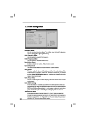
... to adjust PCIE frequency. in advance. Enhance Halt State All processors support the Halt State (C1). Ratio Status This is "Locked" or "Unlocked". 3.4.1 CPU Configuration BIOS SETUP UTILITY Advanced CPU Configuration Overclock Mode CPU Frequency (MHz) PCIE Frequency (MHz) Boot Failure Guard Spread Spectrum [Auto] [200] [100] [Enabled] [Auto] Ratio Status...
... to adjust PCIE frequency. in advance. Enhance Halt State All processors support the Halt State (C1). Ratio Status This is "Locked" or "Unlocked". 3.4.1 CPU Configuration BIOS SETUP UTILITY Advanced CPU Configuration Overclock Mode CPU Frequency (MHz) PCIE Frequency (MHz) Boot Failure Guard Spread Spectrum [Auto] [200] [100] [Enabled] [Auto] Ratio Status...
User Manual
Page 32
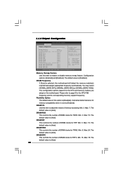
... tRP This controls the number of DRAM clocks for TRP. Min: 9. DRAM tCL Use this option is [Auto]. 32 Min: 15. Max: 78. 3.4.2 Chipset Configuration BIOS SETUP UTILITY Advanced Chipset Configuration Memory Remap Feature [Disabled] DRAM Frequency [Auto] Flexibility Option [Disabled] Standard Memory Info : 5-5-5-15-36-5-3-3-3 DRAM tCL [Auto] DRAM tRCD...
... tRP This controls the number of DRAM clocks for TRP. Min: 9. DRAM tCL Use this option is [Auto]. 32 Min: 15. Max: 78. 3.4.2 Chipset Configuration BIOS SETUP UTILITY Advanced Chipset Configuration Memory Remap Feature [Disabled] DRAM Frequency [Auto] Flexibility Option [Disabled] Standard Memory Info : 5-5-5-15-36-5-3-3-3 DRAM tCL [Auto] DRAM tRCD...

User Manual
Page 34
DRAM RCOMP STRENGTH Configuration BIOS SETUP UTILITY Advanced DRAM RCOMP STRENGTH Settings DRAM CH0 RCOMP STRENGTH Info : 0-10-7-7-7-7 DRAM CH0 G0 (Data) [Auto] DRAM CH0 G1 (Command) [Auto] DRAM CH0 ...
DRAM RCOMP STRENGTH Configuration BIOS SETUP UTILITY Advanced DRAM RCOMP STRENGTH Settings DRAM CH0 RCOMP STRENGTH Info : 0-10-7-7-7-7 DRAM CH0 G0 (Data) [Auto] DRAM CH0 G1 (Command) [Auto] DRAM CH0 ...

User Manual
Page 36
... number of DRAM CH0 CLKSET0 SKEW. The default value is [Auto]. The default value is [Auto]. The default value is [Auto]. DRAM DLL SKEW Settings BIOS SETUP UTILITY Advanced DRAM DLL SKEW Settings DRAM CH0 CLKSET0 SKEW Info:0-0-0-0-0-0 DRAM CH0 CLKSET0 SKEW [Auto] DRAM CH0 CLKSET1 SKEW Info:0-0-0-0-0-0 DRAM CH0 CLKSET1...
... number of DRAM CH0 CLKSET0 SKEW. The default value is [Auto]. The default value is [Auto]. The default value is [Auto]. DRAM DLL SKEW Settings BIOS SETUP UTILITY Advanced DRAM DLL SKEW Settings DRAM CH0 CLKSET0 SKEW Info:0-0-0-0-0-0 DRAM CH0 CLKSET0 SKEW [Auto] DRAM CH0 CLKSET1 SKEW Info:0-0-0-0-0-0 DRAM CH0 CLKSET1...

User Manual
Page 39
... our Intelligent Energy Saver utility to enable this item to enable this function, please set this function. 39 Configuration options: [Enabled] and [Disabled]. Besides the BIOS option, you want to [Enabled]. The default value of this feature is [Auto]. The default value is [Auto]. The default value of this feature is...
... our Intelligent Energy Saver utility to enable this item to enable this function, please set this function. 39 Configuration options: [Enabled] and [Disabled]. Besides the BIOS option, you want to [Enabled]. The default value of this feature is [Auto]. The default value is [Auto]. The default value of this feature is...

User Manual
Page 40
... power state after an unexpected AC/Power loss. Restore on the system from the power-soft-off mode. Select [Auto] will be hidden. 3.4.3 ACPI Configuration BIOS SETUP UTILITY Advanced ACPI Configuration Suspend To RAM Repost Video on STR Resume Check Ready Bit Restore on the system. 40 Suspend to RAM Use...
... power state after an unexpected AC/Power loss. Restore on the system from the power-soft-off mode. Select [Auto] will be hidden. 3.4.3 ACPI Configuration BIOS SETUP UTILITY Advanced ACPI Configuration Suspend To RAM Repost Video on STR Resume Check Ready Bit Restore on the system. 40 Suspend to RAM Use...


