User Manual
Page 6
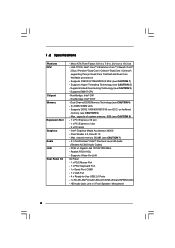
... LED and SPEED LED) - Supports Hyper-Threading Technology (see CAUTION 3) - Realtek RTL8111DL - Supports Untied Overclocking Technology (see CAUTION 2) - Max. shared memory 352MB (see CAUTION 5) - LGA 775 for Intel® CoreTM 2 Extreme / CoreTM 2 Quad / CoreTM 2 Duo / Pentium® Dual Core / Celeron® Dual Core / Celeron®, supporting Penryn Quad Core Yorkfield and...
... LED and SPEED LED) - Supports Hyper-Threading Technology (see CAUTION 3) - Realtek RTL8111DL - Supports Untied Overclocking Technology (see CAUTION 2) - Max. shared memory 352MB (see CAUTION 5) - LGA 775 for Intel® CoreTM 2 Extreme / CoreTM 2 Quad / CoreTM 2 Duo / Pentium® Dual Core / Celeron® Dual Core / Celeron®, supporting Penryn Quad Core Yorkfield and...

User Manual
Page 10
... PLED PWRBTN 1 1 HDLED RESET PANEL 1 USB4_5 USB6_7 1 SPEAKER1 1 SATAII_1 20 19 18 17 16 15 14 13 12 G41M-GS SATAII_2 SATAII_4 24.4cm (9.6 in) 6 7 8 9 10 11 1 PS2_USB_PWR1 Jumper 16 USB 2.0 Header (USB4_5, Blue) 2 775-Pin CPU Socket 17 System Panel Header (PANEL1, Orange) 3 North Bridge Controller 18 BIOS SPI Chip 4 CPU Fan...
... PLED PWRBTN 1 1 HDLED RESET PANEL 1 USB4_5 USB6_7 1 SPEAKER1 1 SATAII_1 20 19 18 17 16 15 14 13 12 G41M-GS SATAII_2 SATAII_4 24.4cm (9.6 in) 6 7 8 9 10 11 1 PS2_USB_PWR1 Jumper 16 USB 2.0 Header (USB4_5, Blue) 2 775-Pin CPU Socket 17 System Panel Header (PANEL1, Orange) 3 North Bridge Controller 18 BIOS SPI Chip 4 CPU Fan...

User Manual
Page 13
...depressing down and out on the socket. Pin1 orientation key notch orientation key notch Pin1 alignment key alignment key 775-LAND CPU 775-Pin Socket 13 Step 1-3. Insert the 775-LAND CPU: Step 2-1. Orient the CPU with black lines. Otherwise, the CPU will be seriously damaged. ... Pin1 and the two orientation key notches. 2.3 CPU Installation For the installation of Intel 775-LAND CPU, please follow the steps below. 775-Pin Socket Overview Before you insert the 775-LAND CPU into the socket if above situation is any bent pin on the ShoockoetkMatrokedcCleoranerr retention...
...depressing down and out on the socket. Pin1 orientation key notch orientation key notch Pin1 alignment key alignment key 775-LAND CPU 775-Pin Socket 13 Step 1-3. Insert the 775-LAND CPU: Step 2-1. Orient the CPU with black lines. Otherwise, the CPU will be seriously damaged. ... Pin1 and the two orientation key notches. 2.3 CPU Installation For the installation of Intel 775-LAND CPU, please follow the steps below. 775-Pin Socket Overview Before you insert the 775-LAND CPU into the socket if above situation is any bent pin on the ShoockoetkMatrokedcCleoranerr retention...
User Manual
Page 15
...see page 10, No. 4). Secure excess cable with tie-wrap to ensure cable does not interfere with remaining fasteners. Below is equipped with 775-Pin socket that the CPU and the heatsink are oriented on side closest to the CPU fan connector on the motherboard. Step 6. Rotate the...heatsink, you press down on fastener caps with thumb to install and lock. 2.4 Installation of heatsink and cooling fan compliant with Intel 775-LAND CPU to dissipate heat. Please adopt the type of CPU Fan and Heatsink This motherboard is an example to illustrate the installation of...
...see page 10, No. 4). Secure excess cable with tie-wrap to ensure cable does not interfere with remaining fasteners. Below is equipped with 775-Pin socket that the CPU and the heatsink are oriented on side closest to the CPU fan connector on the motherboard. Step 6. Rotate the...heatsink, you press down on fastener caps with thumb to install and lock. 2.4 Installation of heatsink and cooling fan compliant with Intel 775-LAND CPU to dissipate heat. Please adopt the type of CPU Fan and Heatsink This motherboard is an example to illustrate the installation of...

Quick Installation Guide
Page 2
... FSB2 / FSB3 Jumper 14 Chassis Speaker Header (SPEAKER 1, Purple) 29 ATX 12V Connector (ATX12V1) 15 USB 2.0 Header (USB6_7, Blue) 2 ASRock G41M-GS Motherboard Orange) 26 PCI Express x1 Slot (PCIE1) 12 Secondary SATAII Connector (SATAII_2; Orange) 25 PCI Express x16 Slot (PCIE2) 11 Fourth SATAII... Connector (SATAII_4; Motherboard Layout English 1 PS2_USB_PWR1 Jumper 16 USB 2.0 Header (USB4_5, Blue) 2 775-Pin CPU Socket 17 System Panel Header (PANEL1, Orange) 3 North Bridge Controller 18 BIOS SPI Chip 4 CPU Fan Connector (CPU_FAN1) 19 ...
... FSB2 / FSB3 Jumper 14 Chassis Speaker Header (SPEAKER 1, Purple) 29 ATX 12V Connector (ATX12V1) 15 USB 2.0 Header (USB6_7, Blue) 2 ASRock G41M-GS Motherboard Orange) 26 PCI Express x1 Slot (PCIE1) 12 Secondary SATAII Connector (SATAII_2; Orange) 25 PCI Express x16 Slot (PCIE2) 11 Fourth SATAII... Connector (SATAII_4; Motherboard Layout English 1 PS2_USB_PWR1 Jumper 16 USB 2.0 Header (USB4_5, Blue) 2 775-Pin CPU Socket 17 System Panel Header (PANEL1, Orange) 3 North Bridge Controller 18 BIOS SPI Chip 4 CPU Fan Connector (CPU_FAN1) 19 ...
Quick Installation Guide
Page 5
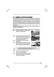
... 2 x DDR2 DIMM slots - Pixel Shader 4.0, DirectX 10 - Micro ATX Form Factor: 9.6-in x 7.6-in / Front Speaker / Microphone English 5 ASRock G41M-GS Motherboard Dual Channel DDR2 Memory Technology (see CAUTION 7) - 5.1 CH Windows® VistaTM Premium Level HD Audio (Realtek ALC662 Audio Codec) - Max. ...Realtek RTL8111DL - Supports Hyper-Threading Technology (see CAUTION 5) - Intel® Graphics Media Accelerator X4500 - LGA 775 for Intel® CoreTM 2 Extreme / CoreTM 2 Quad / CoreTM 2 Duo / Pentium® Dual Core / Celeron® Dual Core...
... 2 x DDR2 DIMM slots - Pixel Shader 4.0, DirectX 10 - Micro ATX Form Factor: 9.6-in x 7.6-in / Front Speaker / Microphone English 5 ASRock G41M-GS Motherboard Dual Channel DDR2 Memory Technology (see CAUTION 7) - 5.1 CH Windows® VistaTM Premium Level HD Audio (Realtek ALC662 Audio Codec) - Max. ...Realtek RTL8111DL - Supports Hyper-Threading Technology (see CAUTION 5) - Intel® Graphics Media Accelerator X4500 - LGA 775 for Intel® CoreTM 2 Extreme / CoreTM 2 Quad / CoreTM 2 Duo / Pentium® Dual Core / Celeron® Dual Core...

Quick Installation Guide
Page 9
... on the socket. When placing screws into the screw holes to secure the motherboard to the motherboard, peripherals, and/or components. 2. Whenever you insert the 775-LAND CPU into the socket if above situation is any motherboard settings. 1. Unplug the power cord from the wall socket before you handle components. 3. Failure... the CPU into the socket, please check if the CPU surface is unclean or if there is found. 2. Otherwise, the CPU will be seriously damaged. 9 ASRock G41M-GS Motherboard English Hold components by the edges and do not over-tighten the screws!
... on the socket. When placing screws into the screw holes to secure the motherboard to the motherboard, peripherals, and/or components. 2. Whenever you insert the 775-LAND CPU into the socket if above situation is any motherboard settings. 1. Unplug the power cord from the wall socket before you handle components. 3. Failure... the CPU into the socket, please check if the CPU surface is unclean or if there is found. 2. Otherwise, the CPU will be seriously damaged. 9 ASRock G41M-GS Motherboard English Hold components by the edges and do not over-tighten the screws!
Quick Installation Guide
Page 10
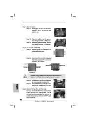
... thumb and peel the cap from the socket while pressing on the hook to fully open position at approximately 100 degrees. Step 3. Insert the 775-LAND CPU: Step 2-1. Rotate the load lever to the orient keys. Step 1-3. Orient the CPU with black lines. Step 2-3. Verify that ...Integrated Heat Sink) up. Remove PnP Cap (Pick and Place Cap): Use your left hand index finger and thumb to assist in removal. 10 ASRock G41M-GS Motherboard Step 1-2. Open the socket: Step 1-1. Disengaging the lever by depressing down and out on center of the socket. Rotate the load plate...
... thumb and peel the cap from the socket while pressing on the hook to fully open position at approximately 100 degrees. Step 3. Insert the 775-LAND CPU: Step 2-1. Rotate the load lever to the orient keys. Step 1-3. Orient the CPU with black lines. Step 2-3. Verify that ...Integrated Heat Sink) up. Remove PnP Cap (Pick and Place Cap): Use your left hand index finger and thumb to assist in removal. 10 ASRock G41M-GS Motherboard Step 1-2. Open the socket: Step 1-1. Disengaging the lever by depressing down and out on center of the socket. Rotate the load plate...

Quick Installation Guide
Page 11
... you press down the fasteners without rotating them clockwise, the heatsink cannot be placed if returning the motherboard for 775-LAND CPU. Secure excess cable with fan operation or contact other components. 11 ASRock G41M-GS Motherboard English Step 4. Close the socket: Step 4-1. Secure load lever with the CPU fan connector on the motherboard...
... you press down the fasteners without rotating them clockwise, the heatsink cannot be placed if returning the motherboard for 775-LAND CPU. Secure excess cable with fan operation or contact other components. 11 ASRock G41M-GS Motherboard English Step 4. Close the socket: Step 4-1. Secure load lever with the CPU fan connector on the motherboard...