
User Manual
Page 5
... any modifications of this manual occur, the updated version will be available on ASRock website as well. www.asrock.com/support/index.asp 1.1 Package Contents ASRock G41M-GS Motherboard (Micro ATX Form Factor: 9.6-in x 7.6-in, 24.4 cm x 19.3 cm) ASRock G41M-GS Quick Installation Guide ASRock G41M-GS Support CD One 80-conductor Ultra ATA 66/100 IDE Ribbon Cable (Optional...
... any modifications of this manual occur, the updated version will be available on ASRock website as well. www.asrock.com/support/index.asp 1.1 Package Contents ASRock G41M-GS Motherboard (Micro ATX Form Factor: 9.6-in x 7.6-in, 24.4 cm x 19.3 cm) ASRock G41M-GS Quick Installation Guide ASRock G41M-GS Support CD One 80-conductor Ultra ATA 66/100 IDE Ribbon Cable (Optional...

Quick Installation Guide
Page 1
...by any defect or error in Perchlorate Best Management Practices (BMP) regulations passed by the California Legislature. All rights reserved. 1 ASRock G41M-GS Motherboard English Products and corporate names appearing in this guide may or may be reproduced, transcribed, transmitted, or translated in any ... in advance. "Perchlorate Material-special handling may cause undesired operation. CALIFORNIA, USA ONLY The Lithium battery adopted on this guide, ASRock does not provide warranty of any language, in this guide. Copyright Notice: No part of this installation guide may not be ...
...by any defect or error in Perchlorate Best Management Practices (BMP) regulations passed by the California Legislature. All rights reserved. 1 ASRock G41M-GS Motherboard English Products and corporate names appearing in this guide may or may be reproduced, transcribed, transmitted, or translated in any ... in advance. "Perchlorate Material-special handling may cause undesired operation. CALIFORNIA, USA ONLY The Lithium battery adopted on this guide, ASRock does not provide warranty of any language, in this guide. Copyright Notice: No part of this installation guide may not be ...

Quick Installation Guide
Page 2
... SATAII Connector (SATAII_4; Red) 28 FSB1 / FSB2 / FSB3 Jumper 14 Chassis Speaker Header (SPEAKER 1, Purple) 29 ATX 12V Connector (ATX12V1) 15 USB 2.0 Header (USB6_7, Blue) 2 ASRock G41M-GS Motherboard Motherboard Layout English 1 PS2_USB_PWR1 Jumper 16 USB 2.0 Header (USB4_5, Blue) 2 775-Pin CPU Socket 17 System Panel Header (PANEL1, Orange) 3 North Bridge Controller 18...
... SATAII Connector (SATAII_4; Red) 28 FSB1 / FSB2 / FSB3 Jumper 14 Chassis Speaker Header (SPEAKER 1, Purple) 29 ATX 12V Connector (ATX12V1) 15 USB 2.0 Header (USB6_7, Blue) 2 ASRock G41M-GS Motherboard Motherboard Layout English 1 PS2_USB_PWR1 Jumper 16 USB 2.0 Header (USB4_5, Blue) 2 775-Pin CPU Socket 17 System Panel Header (PANEL1, Orange) 3 North Bridge Controller 18...

Quick Installation Guide
Page 3
... 1Gbps connection LAN Port * To enable Multi-Streaming function, you need to connect a front panel audio cable to "Quadraphonic" or "Stereo". Then reboot your system. 3 ASRock G41M-GS Motherboard English I/O Panel 1 PS/2 Mouse Port (Green) 2 USB 2.0 Ports (USB23) * 3 RJ-45 Port 4 Line In (Light Blue) 5 Line Out (Lime) 6 Microphone (Pink) 7 USB 2.0 Ports (USB01...
... 1Gbps connection LAN Port * To enable Multi-Streaming function, you need to connect a front panel audio cable to "Quadraphonic" or "Stereo". Then reboot your system. 3 ASRock G41M-GS Motherboard English I/O Panel 1 PS/2 Mouse Port (Green) 2 USB 2.0 Ports (USB23) * 3 RJ-45 Port 4 Line In (Light Blue) 5 Line Out (Lime) 6 Microphone (Pink) 7 USB 2.0 Ports (USB01...

Quick Installation Guide
Page 4
...to this manual occur, the updated version will be found in the user manual presented in , 24.4 cm x 19.3 cm) ASRock G41M-GS Quick Installation Guide ASRock G41M-GS Support CD One 80-conductor Ultra ATA 66/100 IDE Ribbon Cable (Optional) One Serial ATA (SATA) Data Cable (Optional) One...motherboard specifications and the BIOS software might be updated, the content of the motherboard can be available on ASRock website as well. www.asrock.com/support/index.asp 1.1 Package Contents ASRock G41M-GS Motherboard (Micro ATX Form Factor: 9.6-in x 7.6-in the Support CD. In case any modifications ...
...to this manual occur, the updated version will be found in the user manual presented in , 24.4 cm x 19.3 cm) ASRock G41M-GS Quick Installation Guide ASRock G41M-GS Support CD One 80-conductor Ultra ATA 66/100 IDE Ribbon Cable (Optional) One Serial ATA (SATA) Data Cable (Optional) One...motherboard specifications and the BIOS software might be updated, the content of the motherboard can be available on ASRock website as well. www.asrock.com/support/index.asp 1.1 Package Contents ASRock G41M-GS Motherboard (Micro ATX Form Factor: 9.6-in x 7.6-in the Support CD. In case any modifications ...
Quick Installation Guide
Page 5
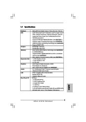
...-Use USB 2.0 Ports - 1 x RJ-45 LAN Port with LED (ACT/LINK LED and SPEED LED) - Micro ATX Form Factor: 9.6-in x 7.6-in / Front Speaker / Microphone English 5 ASRock G41M-GS Motherboard Supports FSB1333/1066/800/533 MHz (see CAUTION 5) - Southbridge: Intel® ICH7 - Supports DDR2 1066/800/667/533 non-ECC, un-buffered memory (see...
...-Use USB 2.0 Ports - 1 x RJ-45 LAN Port with LED (ACT/LINK LED and SPEED LED) - Micro ATX Form Factor: 9.6-in x 7.6-in / Front Speaker / Microphone English 5 ASRock G41M-GS Motherboard Supports FSB1333/1066/800/533 MHz (see CAUTION 5) - Southbridge: Intel® ICH7 - Supports DDR2 1066/800/667/533 non-ECC, un-buffered memory (see...

Quick Installation Guide
Page 6
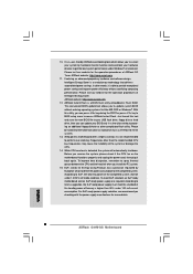
... CAUTION 9) BIOS Feature - 8Mb AMI BIOS - EuP Ready (EuP ready power supply is required) (see CAUTION 14) - ASRock U-COP (see CAUTION 15) * For detailed product information, please visit our website: http://www.asrock.com English 6 ASRock G41M-GS Motherboard Voltage Monitoring: +12V, +5V, +3.3V, Vcore OS - Microsoft® Windows® 2000 / XP / XP 64-bit...
... CAUTION 9) BIOS Feature - 8Mb AMI BIOS - EuP Ready (EuP ready power supply is required) (see CAUTION 14) - ASRock U-COP (see CAUTION 15) * For detailed product information, please visit our website: http://www.asrock.com English 6 ASRock G41M-GS Motherboard Voltage Monitoring: +12V, +5V, +3.3V, Vcore OS - Microsoft® Windows® 2000 / XP / XP 64-bit...

Quick Installation Guide
Page 7
... settings. 2. Due to the operating system limitation, the actual memory size may affect your system stability, or even cause damage to SATAII connector directly. 9. English 7 ASRock G41M-GS Motherboard For special overclocking mode, please refer to page 15 for details. 4. Before installing SATAII hard disk to SATAII connector, please read "Untied Overclocking Technology...
... settings. 2. Due to the operating system limitation, the actual memory size may affect your system stability, or even cause damage to SATAII connector directly. 9. English 7 ASRock G41M-GS Motherboard For special overclocking mode, please refer to page 15 for details. 4. Before installing SATAII hard disk to SATAII connector, please read "Untied Overclocking Technology...
Quick Installation Guide
Page 8
...stepless control, it back again. While CPU overheat is a BIOS flash utility embedded in off mode condition. 10. Please be under Windows® environment. ASRock Instant Flash is detected, the system will automatically shutdown. To meet the standard of the completed system shall be noted that delivers unparalleled power savings... EuP, the total AC power of 5v standby power efficiency is not recommended to get the best system performance under 1.00W in Flash ROM. ASRock website: http://www.asrock.com 12. EuP, stands for more details. 8 ASRock G41M-GS Motherboard English
...stepless control, it back again. While CPU overheat is a BIOS flash utility embedded in off mode condition. 10. Please be under Windows® environment. ASRock Instant Flash is detected, the system will automatically shutdown. To meet the standard of the completed system shall be noted that delivers unparalleled power savings... EuP, the total AC power of 5v standby power efficiency is not recommended to get the best system performance under 1.00W in Flash ROM. ASRock website: http://www.asrock.com 12. EuP, stands for more details. 8 ASRock G41M-GS Motherboard English

Quick Installation Guide
Page 9
... screws into the socket if above situation is any component, place it on the carpet or the like. Otherwise, the CPU will be seriously damaged. 9 ASRock G41M-GS Motherboard English Installation Pre-installation Precautions Take note of Intel 775-LAND CPU, please follow the steps below. 775-Pin Socket Overview Before you install...
... screws into the socket if above situation is any component, place it on the carpet or the like. Otherwise, the CPU will be seriously damaged. 9 ASRock G41M-GS Motherboard English Installation Pre-installation Precautions Take note of Intel 775-LAND CPU, please follow the steps below. 775-Pin Socket Overview Before you install...
Quick Installation Guide
Page 10
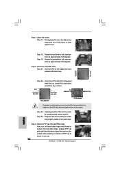
... approximately 135 degrees. Step 2-4. Open the socket: Step 1-1. Disengaging the lever by using a purely vertical motion. Rotate the load lever to assist in removal. 10 ASRock G41M-GS Motherboard Rotate the load plate to clear retention tab. Insert the 775-LAND CPU: Step 2-1. Locate Pin1 and the two orientation key notches. Step 1. Orient...
... approximately 135 degrees. Step 2-4. Open the socket: Step 1-1. Disengaging the lever by using a purely vertical motion. Rotate the load lever to assist in removal. 10 ASRock G41M-GS Motherboard Rotate the load plate to clear retention tab. Insert the 775-LAND CPU: Step 2-1. Locate Pin1 and the two orientation key notches. Step 1. Orient...

Quick Installation Guide
Page 11
... the load lever. Step 3. Ensure fan cables are oriented on side closest to install and lock. Repeat with fan operation or contact other components. 11 ASRock G41M-GS Motherboard English Step 4-3. Apply thermal interface material onto center of IHS on fastener caps with load plate tab under retention tab of load lever. 2.2 Installation...
... the load lever. Step 3. Ensure fan cables are oriented on side closest to install and lock. Repeat with fan operation or contact other components. 11 ASRock G41M-GS Motherboard English Step 4-3. Apply thermal interface material onto center of IHS on fastener caps with load plate tab under retention tab of load lever. 2.2 Installation...

Quick Installation Guide
Page 12
... DIMM if you force the DIMM into the slot at incorrect orientation. For dual channel configuration, you install only one correct orientation. ASRock G41M-GS Motherboard 2.3 Installation of Memory Modules (DIMM) G41M-GS motherboard provides two 240-pin DDR2 (Double Data Rate 2) DIMM slots, and supports Dual Channel Memory Technology. Otherwise, it is not allowed...
... DIMM if you force the DIMM into the slot at incorrect orientation. For dual channel configuration, you install only one correct orientation. ASRock G41M-GS Motherboard 2.3 Installation of Memory Modules (DIMM) G41M-GS motherboard provides two 240-pin DDR2 (Double Data Rate 2) DIMM slots, and supports Dual Channel Memory Technology. Otherwise, it is not allowed...

Quick Installation Guide
Page 13
... the power cord is completely seated on this motherboard. 2.4 Expansion Slots (PCI and PCI Express Slots) There are used to the chassis with screws. 13 ASRock G41M-GS Motherboard English Please read the documentation of the expansion card and make sure that you start the installation. Step 4.
... the power cord is completely seated on this motherboard. 2.4 Expansion Slots (PCI and PCI Express Slots) There are used to the chassis with screws. 13 ASRock G41M-GS Motherboard English Please read the documentation of the expansion card and make sure that you start the installation. Step 4.

Quick Installation Guide
Page 14
... ready motherboard and a power supply that when EUP_LAN jumper is able to Disk), and S5 (Soft Off) will be disabled. (Disable EuP) 14 ASRock G41M-GS Motherboard Please be noticed that the 5VSB power efficiency is higher than 50% under 100mA current consumption, your system is set to enabled, the Wake-...
... ready motherboard and a power supply that when EUP_LAN jumper is able to Disk), and S5 (Soft Off) will be disabled. (Disable EuP) 14 ASRock G41M-GS Motherboard Please be noticed that the 5VSB power efficiency is higher than 50% under 100mA current consumption, your system is set to enabled, the Wake-...
Quick Installation Guide
Page 15
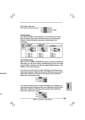
... you adopt below DRAM / CPU configuration on this motherboard, you need to adjust the jumpers. Please follow the instructions below to below jumper settings. 15 ASRock G41M-GS Motherboard English Please use jumper to force NB to below jumper settings. Please short pin4, pin5 for FSB2 jumper and pin4, pin5 for FSB3 jumper...
... you adopt below DRAM / CPU configuration on this motherboard, you need to adjust the jumpers. Please follow the instructions below to below jumper settings. 15 ASRock G41M-GS Motherboard English Please use jumper to force NB to below jumper settings. Please short pin4, pin5 for FSB2 jumper and pin4, pin5 for FSB3 jumper...

Quick Installation Guide
Page 16
.... Serial ATA (SATA) Data Cable (Optional) Either end of the SATA data cable can be connected to the power connector of the power supply. 16 ASRock G41M-GS Motherboard English Then connect the white end of the connector. 2.6 Onboard Headers and Connectors Onboard headers and connectors are NOT jumpers. FDD connector (33-pin...
.... Serial ATA (SATA) Data Cable (Optional) Either end of the SATA data cable can be connected to the power connector of the power supply. 16 ASRock G41M-GS Motherboard English Then connect the white end of the connector. 2.6 Onboard Headers and Connectors Onboard headers and connectors are NOT jumpers. FDD connector (33-pin...

Quick Installation Guide
Page 17
... correctly. USB 2.0 Headers (9-pin USB6_7) (see p.2 No. 15) (9-pin USB4_5) (see p.2 No. 16) Besides four default USB 2.0 ports on the I /O", select "Connector Settings" , choose 17 ASRock G41M-GS Motherboard English Each USB 2.0 header can support two USB 2.0 ports.
... correctly. USB 2.0 Headers (9-pin USB6_7) (see p.2 No. 15) (9-pin USB4_5) (see p.2 No. 16) Besides four default USB 2.0 ports on the I /O", select "Connector Settings" , choose 17 ASRock G41M-GS Motherboard English Each USB 2.0 header can support two USB 2.0 ports.

Quick Installation Guide
Page 18
... Fan Connector (4-pin CPU_FAN1) (see p.2 No. 17) This header accommodates several system front panel functions. Though this header. Pin 1-3 Connected 3-Pin Fan Installation English 18 ASRock G41M-GS Motherboard Please connect a chassis fan cable to this connector and match the black wire to this motherboard provides 4-Pin CPU fan (Quiet Fan) support, the...
... Fan Connector (4-pin CPU_FAN1) (see p.2 No. 17) This header accommodates several system front panel functions. Though this header. Pin 1-3 Connected 3-Pin Fan Installation English 18 ASRock G41M-GS Motherboard Please connect a chassis fan cable to this connector and match the black wire to this motherboard provides 4-Pin CPU fan (Quiet Fan) support, the...

Quick Installation Guide
Page 19
Failing to do so will cause the failure to power up. English tion 19 ASRock G41M-GS Motherboard To use the 20-pin ATX power supply, please plug your power supply along with ATX 12V plug to this motherboard provides 24-pin ...
Failing to do so will cause the failure to power up. English tion 19 ASRock G41M-GS Motherboard To use the 20-pin ATX power supply, please plug your power supply along with ATX 12V plug to this motherboard provides 24-pin ...


