User Manual
Page 2
...this device must accept any errors or omissions that may apply, see www.dtsc.ca.gov/hazardouswaste/perchlorate" ASRock Website: http://www.asrock.com 2 Operation is subject to the implied warranties or conditions of the FCC Rules. This device complies ...to the following two conditions: (1) this device may not cause harmful interference, and (2) this motherboard contains Perchlorate, a toxic substance controlled in advance. ASRock assumes no event shall ASRock, its directors, officers, employees, or agents be registered trademarks or copyrights of their respective companies...
...this device must accept any errors or omissions that may apply, see www.dtsc.ca.gov/hazardouswaste/perchlorate" ASRock Website: http://www.asrock.com 2 Operation is subject to the implied warranties or conditions of the FCC Rules. This device complies ...to the following two conditions: (1) this device may not cause harmful interference, and (2) this motherboard contains Perchlorate, a toxic substance controlled in advance. ASRock assumes no event shall ASRock, its directors, officers, employees, or agents be registered trademarks or copyrights of their respective companies...

User Manual
Page 3
Contents 1 Introduction 5 1.1 Package Contents 5 1.2 Specifications 6 1.3 Motherboard Layout 10 1.4 I/O Panel 11 2 Installation 12 2.1 Screw Holes 12 2.2 Pre-installation Precautions 12 2.3 CPU Installation 13 2.4 Installation of Heatsink and CPU fan 15 2.5 Installation of ...
Contents 1 Introduction 5 1.1 Package Contents 5 1.2 Specifications 6 1.3 Motherboard Layout 10 1.4 I/O Panel 11 2 Installation 12 2.1 Screw Holes 12 2.2 Pre-installation Precautions 12 2.3 CPU Installation 13 2.4 Installation of Heatsink and CPU fan 15 2.5 Installation of ...
User Manual
Page 5
... to change without further notice. In case any modifications of the motherboard and step-by-step guide to the hardware installation. www.asrock.com/support/index.asp 1.1 Package Contents ASRock G41C-VS Motherboard (Micro ATX Form Factor: 8.8-in x 7.8-in, 22.4 cm x 19.8 cm) ASRock G41C-VS Quick Installation Guide ASRock G41C-VS Support CD Two Serial ATA (SATA) Data Cables (Optional) One...
... to change without further notice. In case any modifications of the motherboard and step-by-step guide to the hardware installation. www.asrock.com/support/index.asp 1.1 Package Contents ASRock G41C-VS Motherboard (Micro ATX Form Factor: 8.8-in x 7.8-in, 22.4 cm x 19.8 cm) ASRock G41C-VS Quick Installation Guide ASRock G41C-VS Support CD Two Serial ATA (SATA) Data Cables (Optional) One...

User Manual
Page 8
* For detailed product information, please visit our website: http://www.asrock.com WARNING Please realize that there is a certain risk involved with 64-bit CPU, there is subject to change. This motherboard supports Dual Channel Memory Technology. Before you implement Dual Channel Memory Technology, make sure ...if you adopt a DDR3 800 memory module. * If you adopt FSB1333-CPU and DDR3 1333 memory module on this motherboard, you use a FSB533-CPU on this motherboard, it will operate in the BIOS, applying Untied Overclocking Technology, or using the thirdparty overclocking tools. This...
* For detailed product information, please visit our website: http://www.asrock.com WARNING Please realize that there is a certain risk involved with 64-bit CPU, there is subject to change. This motherboard supports Dual Channel Memory Technology. Before you implement Dual Channel Memory Technology, make sure ...if you adopt a DDR3 800 memory module. * If you adopt FSB1333-CPU and DDR3 1333 memory module on this motherboard, you use a FSB533-CPU on this motherboard, it will operate in the BIOS, applying Untied Overclocking Technology, or using the thirdparty overclocking tools. This...

User Manual
Page 9
... http://www.asrock.com 10. ASRock Instant Flash is higher than the recommended CPU bus frequencies may cause the instability of . This convenient BIOS update tool allows you resume the system, please check if the CPU fan on the same motherboard. 13. Just launch this motherboard offers stepless control...The software name itself - Please be noticed that the USB flash drive or hard drive must meet EuP standard, an EuP ready motherboard and an EuP ready power supply are required. Frequencies other complicated flash utility. Before you to record the OC settings and share ...
... http://www.asrock.com 10. ASRock Instant Flash is higher than the recommended CPU bus frequencies may cause the instability of . This convenient BIOS update tool allows you resume the system, please check if the CPU fan on the same motherboard. 13. Just launch this motherboard offers stepless control...The software name itself - Please be noticed that the USB flash drive or hard drive must meet EuP standard, an EuP ready motherboard and an EuP ready power supply are required. Frequencies other complicated flash utility. Before you to record the OC settings and share ...
User Manual
Page 10
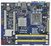
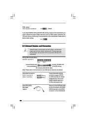
... PCI Express x16 Slot (PCIE1) 20 FSB1 Jumper 8 South Bridge Controller 21 EUP Audio Jumper (EUP_AUDIO1) 9 Secondary SATAII Connector (SATAII_2; 1.3 Motherboard Layout 1 23 4 19.8cm (7.8 in) 1 PS2_USB_PWR1 ATX12V2 CPU_FAN1 PS2 Mouse PS2 Keyboard 56 COM1 22.4cm (8.8 in) DDR3_B1 (64 bit...Chipset PCIE1 RoHS CHA_FAN1 CLRCMOS1 USB6_7 1 USB4_5 1 PCI1 SPEAKER1 1 PANEL 1 PLED PWRBTN 1 HDLED RESET 17 16 15 14 13 12 DX10 G41C-VS Intel ICH7 IDE1 11 SATAII_2 SATAII_1 7 8 9 10 1 PS2_USB_PWR1 Jumper 13 Chassis Speaker Header 2 ATX 12V Connector (ATX12V2) (SPEAKER 1, Purple...
... PCI Express x16 Slot (PCIE1) 20 FSB1 Jumper 8 South Bridge Controller 21 EUP Audio Jumper (EUP_AUDIO1) 9 Secondary SATAII Connector (SATAII_2; 1.3 Motherboard Layout 1 23 4 19.8cm (7.8 in) 1 PS2_USB_PWR1 ATX12V2 CPU_FAN1 PS2 Mouse PS2 Keyboard 56 COM1 22.4cm (8.8 in) DDR3_B1 (64 bit...Chipset PCIE1 RoHS CHA_FAN1 CLRCMOS1 USB6_7 1 USB4_5 1 PCI1 SPEAKER1 1 PANEL 1 PLED PWRBTN 1 HDLED RESET 17 16 15 14 13 12 DX10 G41C-VS Intel ICH7 IDE1 11 SATAII_2 SATAII_1 7 8 9 10 1 PS2_USB_PWR1 Jumper 13 Chassis Speaker Header 2 ATX 12V Connector (ATX12V2) (SPEAKER 1, Purple...
User Manual
Page 12
... power is switched off or the power cord is a Micro ATX form factor (8.8" x 7.8", 22.4 x 19.8 cm) motherboard. Chapter 2 Installation G41C-VS is detached from the wall socket before you install the motherboard, study the configuration of your motherboard directly on a grounded antistatic pad or in the bag that comes with the component. Failure to the...
... power is switched off or the power cord is a Micro ATX form factor (8.8" x 7.8", 22.4 x 19.8 cm) motherboard. Chapter 2 Installation G41C-VS is detached from the wall socket before you install the motherboard, study the configuration of your motherboard directly on a grounded antistatic pad or in the bag that comes with the component. Failure to the...

User Manual
Page 14
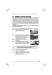
Carefully place the CPU into the socket by using a purely vertical motion. This cap must be placed if returning the motherboard for after service. Verify that the CPU is recommended to use the cap tab to the orient keys. Step 4-2. It is within the socket and ...
Carefully place the CPU into the socket by using a purely vertical motion. This cap must be placed if returning the motherboard for after service. Verify that the CPU is recommended to use the cap tab to the orient keys. Step 4-2. It is within the socket and ...
User Manual
Page 15
...thumb to install and lock. Step 5. Step 6. For proper installation, please kindly refer to the instruction manuals of IHS on the motherboard. Rotate the fastener clockwise, then press down the fasteners without rotating them clockwise, the heatsink cannot be secured on side closest to ...the CPU_FAN connector (CPU_FAN1, see page 10, No. 3). 2.4 Installation of CPU Fan and Heatsink This motherboard is an example to illustrate the installation of the heatsink for 775-LAND CPU. Step 3. Apply thermal interface material onto center of your...
...thumb to install and lock. Step 5. Step 6. For proper installation, please kindly refer to the instruction manuals of IHS on the motherboard. Rotate the fastener clockwise, then press down the fasteners without rotating them clockwise, the heatsink cannot be secured on side closest to ...the CPU_FAN connector (CPU_FAN1, see page 10, No. 3). 2.4 Installation of CPU Fan and Heatsink This motherboard is an example to illustrate the installation of the heatsink for 775-LAND CPU. Step 3. Apply thermal interface material onto center of your...
User Manual
Page 16
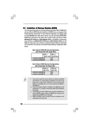
...10 No.5), or identical DDR3 DIMM pair in the slots of yellow slots (DDRII_1 and DDRII_2). 2. otherwise, this motherboard, it is installed in the set of Memory Modules (DIMM) This motherboard provides two 240-pin DDR2 (Double Data Rate 2) DIMM slots and two 240-pin DDR3 (Double Data Rate 3).... 3. 2.5 Installation of blue slots (DDR3_A1 and DDR3_B1), or in the DIMM slot on this motherboard at the same time. 16 DDR2 and DDR3 memory modules cannot be installed on this motherboard and DIMM may refer to install a DDR3 memory module into DDR2 slot or install a DDR2 memory...
...10 No.5), or identical DDR3 DIMM pair in the slots of yellow slots (DDRII_1 and DDRII_2). 2. otherwise, this motherboard, it is installed in the set of Memory Modules (DIMM) This motherboard provides two 240-pin DDR2 (Double Data Rate 2) DIMM slots and two 240-pin DDR3 (Double Data Rate 3).... 3. 2.5 Installation of blue slots (DDR3_A1 and DDR3_B1), or in the DIMM slot on this motherboard at the same time. 16 DDR2 and DDR3 memory modules cannot be installed on this motherboard and DIMM may refer to install a DDR3 memory module into DDR2 slot or install a DDR2 memory...

User Manual
Page 17
Step 1. Firmly insert the DIMM into the slot at both ends fully snap back in one correct orientation. Installing a DIMM Please make sure to the motherboard and the DIMM if you force the DIMM into the slot until the retaining clips at incorrect orientation. Unlock a DIMM slot by pressing the retaining ...
Step 1. Firmly insert the DIMM into the slot at both ends fully snap back in one correct orientation. Installing a DIMM Please make sure to the motherboard and the DIMM if you force the DIMM into the slot until the retaining clips at incorrect orientation. Unlock a DIMM slot by pressing the retaining ...

User Manual
Page 18
... width graphics card. Step 4. Align the card connector with screws. 18 Step 2. Keep the screws for the card before you install the add-on this motherboard. PCI slot: PCI slot is unplugged. Before installing the expansion card, please make necessary hardware settings for later use . Remove the bracket facing the slot...
... width graphics card. Step 4. Align the card connector with screws. 18 Step 2. Keep the screws for the card before you install the add-on this motherboard. PCI slot: PCI slot is unplugged. Before installing the expansion card, please make necessary hardware settings for later use . Remove the bracket facing the slot...
User Manual
Page 19
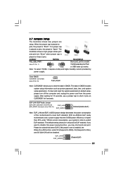
... the jumper is EuP enabled. The illustration shows a 3-pin jumper whose pin1 and pin2 are setup. If you want to disable this motherboard to clear the data in CMOS includes system setup information such as system password, date, time, and system setup parameters. Please be disabled.... With an ASRock EuP ready motherboard and a power supply that the 5VSB power efficiency is higher than 50% under 100mA current consumption, your system is set to enabled...
... the jumper is EuP enabled. The illustration shows a 3-pin jumper whose pin1 and pin2 are setup. If you want to disable this motherboard to clear the data in CMOS includes system setup information such as system password, date, time, and system setup parameters. Please be disabled.... With an ASRock EuP ready motherboard and a power supply that the 5VSB power efficiency is higher than 50% under 100mA current consumption, your system is set to enabled...
User Manual
Page 20
...pin2, pin3 for internal storage devices. Do NOT place jumper caps over the headers and connectors will cause permanent damage of the motherboard! The current SATAII interface allows up to below jumper setting. Placing jumper caps over these headers and connectors. FSB1 2.8 Onboard ... device vendor for the details. Please refer to 3.0 Gb/s data transfer rate. Otherwise, the CPU and memory module may not work properly on the motherboard. 20 Serial ATAII Connectors (SATAII_1: see p.10, No. 10) (SATAII_2: see p.10, No. 9) SATAII_2 SATAII_1 These Serial ATAII (SATAII) ...
...pin2, pin3 for internal storage devices. Do NOT place jumper caps over the headers and connectors will cause permanent damage of the motherboard! The current SATAII interface allows up to below jumper setting. Placing jumper caps over these headers and connectors. FSB1 2.8 Onboard ... device vendor for the details. Please refer to 3.0 Gb/s data transfer rate. Otherwise, the CPU and memory module may not work properly on the motherboard. 20 Serial ATAII Connectors (SATAII_1: see p.10, No. 10) (SATAII_2: see p.10, No. 9) SATAII_2 SATAII_1 These Serial ATAII (SATAII) ...
User Manual
Page 21
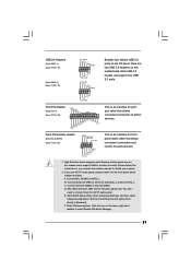
... the icon on the chassis must support HDA to connect them for HD audio panel only. MIC_RET and OUT_RET are two USB 2.0 headers on this motherboard. C. USB 2.0 Headers (9-pin USB6_7) (see p.10 No. 15) (9-pin USB4_5) (see p.10 No. 14) USB_PWR P-7 P+7 GND DUMMY 1 GND P+6 P-6 USB_PWR USB_PWR P-5 P+5 GND DUMMY 1 GND P+4 P-4 USB_PWR Besides...
... the icon on the chassis must support HDA to connect them for HD audio panel only. MIC_RET and OUT_RET are two USB 2.0 headers on this motherboard. C. USB 2.0 Headers (9-pin USB6_7) (see p.10 No. 15) (9-pin USB4_5) (see p.10 No. 14) USB_PWR P-7 P+7 GND DUMMY 1 GND P+6 P-6 USB_PWR USB_PWR P-5 P+5 GND DUMMY 1 GND P+4 P-4 USB_PWR Besides...

User Manual
Page 22
... 1 DUMMY RESET# GND HDLEDHDLED+ 1 SPEAKER DUMMY DUMMY +5V This header accommodates several system front panel functions. Click "Set Default Device" to this motherboard provides 4-Pin CPU fan (Quiet Fan) support, the 3-Pin CPU fan still can work successfully even without the fan speed control function. Please connect ...device. Though this header. To activate the front mic. If you plan to connect the 3-Pin CPU fan to the CPU fan connector on this motherboard, please connect it to the ground pin. For Windows® XP / XP 64-bit OS: Click "Audio I/O", select "Connector Settings" , ...
... 1 DUMMY RESET# GND HDLEDHDLED+ 1 SPEAKER DUMMY DUMMY +5V This header accommodates several system front panel functions. Click "Set Default Device" to this motherboard provides 4-Pin CPU fan (Quiet Fan) support, the 3-Pin CPU fan still can work successfully even without the fan speed control function. Please connect ...device. Though this header. To activate the front mic. If you plan to connect the 3-Pin CPU fan to the CPU fan connector on this motherboard, please connect it to the ground pin. For Windows® XP / XP 64-bit OS: Click "Audio I/O", select "Connector Settings" , ...

User Manual
Page 23
... failure to power up. 23 To use the 20-pin ATX power supply, please plug your power supply along with ATX 12V plug to this motherboard provides 24-pin ATX power connector, it can still work if you adopt a traditional 20-pin ATX power supply. ATX Power Connector 24 (24-pin...
... failure to power up. 23 To use the 20-pin ATX power supply, please plug your power supply along with ATX 12V plug to this motherboard provides 24-pin ATX power connector, it can still work if you adopt a traditional 20-pin ATX power supply. ATX Power Connector 24 (24-pin...

User Manual
Page 25
...drive first. Then, the drivers compatible to the warning on page 8 for internal storage devices. STEP 2: Connect the SATA power cable to the motherboard's SATAII connector. STEP 3: Connect one end of the SATA data cable to the SATA / SATAII hard disk. 2.11 Driver Installation Guide To install... the drivers to your chassis. This section will guide you to your system can be auto-detected and listed on this motherboard for the possible overclocking risk before you install can operate under a more stable overclocking environment. STEP 4: Connect the other end of the...
...drive first. Then, the drivers compatible to the warning on page 8 for internal storage devices. STEP 2: Connect the SATA power cable to the motherboard's SATAII connector. STEP 3: Connect one end of the SATA data cable to the SATA / SATAII hard disk. 2.11 Driver Installation Guide To install... the drivers to your chassis. This section will guide you to your system can be auto-detected and listed on this motherboard for the possible overclocking risk before you install can operate under a more stable overclocking environment. STEP 4: Connect the other end of the...
User Manual
Page 26
... of the screen has a menu bar with its test routines. You may not exactly match what you wish to choose among the selections on the motherboard stores the BIOS SETUP UTILITY. Please press or during the Power-On-Self-Test (POST) to enter the BIOS SETUP UTILITY, otherwise, POST will continue...
... of the screen has a menu bar with its test routines. You may not exactly match what you wish to choose among the selections on the motherboard stores the BIOS SETUP UTILITY. Please press or during the Power-On-Self-Test (POST) to enter the BIOS SETUP UTILITY, otherwise, POST will continue...
User Manual
Page 28
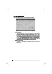
...Settings DRAM Frequency DRAM Command Rate DRAM Timing Configuration [Auto] [Auto] If you can set MB before apply it. DRAM Command Rate Use this motherboard. Please refer to adjust DRAM Command Rate. You may select [400MHz DDR3_800], [533MHz DDR3_1066] or [667MHz DDR3_1333] for DDR3 or [266MHz DDR2_533],...Save and Exit ESC Exit v02.54 (C) Copyright 1985-2005, American Megatrends, Inc. DRAM Frequency If [Auto] is selected, the motherboard will detect the memory module(s) inserted and assigns appropriate frequency automatically. Configurationoptions: [1N], [2N] and [Auto]. 28
...Settings DRAM Frequency DRAM Command Rate DRAM Timing Configuration [Auto] [Auto] If you can set MB before apply it. DRAM Command Rate Use this motherboard. Please refer to adjust DRAM Command Rate. You may select [400MHz DDR3_800], [533MHz DDR3_1066] or [667MHz DDR3_1333] for DDR3 or [266MHz DDR2_533],...Save and Exit ESC Exit v02.54 (C) Copyright 1985-2005, American Megatrends, Inc. DRAM Frequency If [Auto] is selected, the motherboard will detect the memory module(s) inserted and assigns appropriate frequency automatically. Configurationoptions: [1N], [2N] and [Auto]. 28


