
User Manual
Page 10
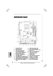
... 1 USB6_7 1 SPEAKER1 1 SATAII_1 19 18 17 16 15 14 13 12 SATAII_2 SATAII_4 6 7 8 9 10 11 1 PS2_USB_PWR1 Jumper 15 USB 2.0 Header (USB6_7, Blue) 2 775-Pin CPU Socket 16 USB 2.0 Header (USB4_5, Blue) 3 North Bridge Controller 17 System Panel Header (PANEL1, Orange) 4 CPU Fan Connector (CPU_FAN1) 18 BIOS SPI Chip 5 2 x 240-pin DDR2...
... 1 USB6_7 1 SPEAKER1 1 SATAII_1 19 18 17 16 15 14 13 12 SATAII_2 SATAII_4 6 7 8 9 10 11 1 PS2_USB_PWR1 Jumper 15 USB 2.0 Header (USB6_7, Blue) 2 775-Pin CPU Socket 16 USB 2.0 Header (USB4_5, Blue) 3 North Bridge Controller 17 System Panel Header (PANEL1, Orange) 4 CPU Fan Connector (CPU_FAN1) 18 BIOS SPI Chip 5 2 x 240-pin DDR2...
User Manual
Page 12
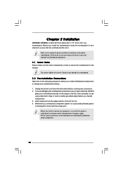
... or change any component, ensure that comes with the component. Unplug the power cord from the power supply. Before you uninstall any component. 2. Chapter 2 Installation G31M-GS / G31M-S is detached from the wall socket before installing or removing the motherboard.
... or change any component, ensure that comes with the component. Unplug the power cord from the power supply. Before you uninstall any component. 2. Chapter 2 Installation G31M-GS / G31M-S is detached from the wall socket before installing or removing the motherboard.
User Manual
Page 13
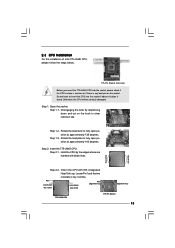
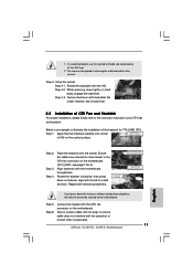
... 2.3 CPU Installation For the installation of Intel 775-LAND CPU, please follow the steps below. 775-Pin Socket Overview Before you insert the 775-LAND CPU into the socket if above situation is any bent pin on the ShoockoetkMatrokedcCleoranerr retention tab. DLifitsLeevnergUapgtoin9g0° the lever by the ... open position at approximately 135 degrees. Orient the CPU with black lines. Rotate the load plate to insert the CPU into the socket, please check if the CPU surface is unclean or if there is found. Pin1 orientation key notch orientation key notch Pin1 alignment ...
... 2.3 CPU Installation For the installation of Intel 775-LAND CPU, please follow the steps below. 775-Pin Socket Overview Before you insert the 775-LAND CPU into the socket if above situation is any bent pin on the ShoockoetkMatrokedcCleoranerr retention tab. DLifitsLeevnergUapgtoin9g0° the lever by the ... open position at approximately 135 degrees. Orient the CPU with black lines. Rotate the load plate to insert the CPU into the socket, please check if the CPU surface is unclean or if there is found. Pin1 orientation key notch orientation key notch Pin1 alignment ...

User Manual
Page 14
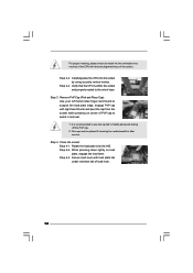
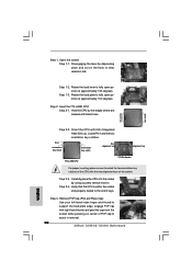
.... For proper inserting, please ensure to match the two orientation key notches of the CPU with right hand thumb and peel the cap from the socket while pressing on load plate, engage the load lever. Step 3. Remove PnP Cap (Pick and Place Cap): Use your left hand index finger and thumb... the load plate edge, engage PnP cap with the two alignment keys of load lever. 14 Close the socket: Step 4-1. Step 2-4. Step 4-3. Secure load lever with load plate tab under retention tab of the socket. Verify that the CPU is recommended to use the cap tab to assist in removal. 1. Step 4. Step...
.... For proper inserting, please ensure to match the two orientation key notches of the CPU with right hand thumb and peel the cap from the socket while pressing on load plate, engage the load lever. Step 3. Remove PnP Cap (Pick and Place Cap): Use your left hand index finger and thumb... the load plate edge, engage PnP cap with the two alignment keys of load lever. 14 Close the socket: Step 4-1. Step 2-4. Step 4-3. Secure load lever with load plate tab under retention tab of the socket. Verify that the CPU is recommended to use the cap tab to assist in removal. 1. Step 4. Step...

User Manual
Page 15
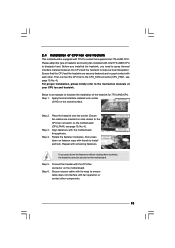
... lock. Step 1. Repeat with Intel 775-LAND CPU to ensure cable does not interfere with 775-Pin socket that the CPU and the heatsink are oriented on the motherboard. Place the heatsink onto the socket. Secure excess cable with tie-wrap to dissipate heat. Before you installed the heatsink, you press down... Fan and Heatsink This motherboard is an example to improve heat dissipation. For proper installation, please kindly refer to the CPU fan connector on the socket surface.
... lock. Step 1. Repeat with Intel 775-LAND CPU to ensure cable does not interfere with 775-Pin socket that the CPU and the heatsink are oriented on the motherboard. Place the heatsink onto the socket. Secure excess cable with tie-wrap to dissipate heat. Before you installed the heatsink, you press down... Fan and Heatsink This motherboard is an example to improve heat dissipation. For proper installation, please kindly refer to the CPU fan connector on the socket surface.
User Manual (VIA)
Page 10
... 1 USB6_7 1 SPEAKER1 1 SATAII_1 19 18 17 16 15 14 13 12 SATAII_2 SATAII_4 6 7 8 9 10 11 1 PS2_USB_PWR1 Jumper 15 USB 2.0 Header (USB6_7, Blue) 2 775-Pin CPU Socket 16 USB 2.0 Header (USB4_5, Blue) 3 North Bridge Controller 17 System Panel Header (PANEL1, Orange) 4 CPU Fan Connector (CPU_FAN1) 18 BIOS SPI Chip 5 2 x 240-pin DDR2...
... 1 USB6_7 1 SPEAKER1 1 SATAII_1 19 18 17 16 15 14 13 12 SATAII_2 SATAII_4 6 7 8 9 10 11 1 PS2_USB_PWR1 Jumper 15 USB 2.0 Header (USB6_7, Blue) 2 775-Pin CPU Socket 16 USB 2.0 Header (USB4_5, Blue) 3 North Bridge Controller 17 System Panel Header (PANEL1, Orange) 4 CPU Fan Connector (CPU_FAN1) 18 BIOS SPI Chip 5 2 x 240-pin DDR2...

User Manual (VIA)
Page 12
...to the motherboard, peripherals, and/or components. 12 Failure to do so may cause physical injuries to you handle components. 3. Chapter 2 Installation G31M-GS / G31M-S is detached from the power supply. Before you install motherboard components or change any component, ensure that the motherboard fits into it on the ...carpet or the like. Unplug the power cord from the wall socket before you install the motherboard, study the configuration of the following precautions before touching any component, place it .
...to the motherboard, peripherals, and/or components. 12 Failure to do so may cause physical injuries to you handle components. 3. Chapter 2 Installation G31M-GS / G31M-S is detached from the power supply. Before you install motherboard components or change any component, ensure that the motherboard fits into it on the ...carpet or the like. Unplug the power cord from the wall socket before you install the motherboard, study the configuration of the following precautions before touching any component, place it .

User Manual (VIA)
Page 13
...notches. Pin1 orientation key notch orientation key notch Pin1 alignment key alignment key 775-LAND CPU 775-Pin Socket 13 Step 1-2. Insert the 775-LAND CPU: Step 2-1. Open the socket: CPU Marked Corner Step 1-1. Rotate the load lever to fully open position at approximately 100 degrees.... CPU Installation For the installation of Intel 775-LAND CPU, please follow the steps below. 775-Pin Socket Overview Before you insert the 775-LAND CPU into the socket if above situation is any bent pin on the ShoockoetkMatrokedcCleoranerr retention tab. Do not force to insert the ...
...notches. Pin1 orientation key notch orientation key notch Pin1 alignment key alignment key 775-LAND CPU 775-Pin Socket 13 Step 1-2. Insert the 775-LAND CPU: Step 2-1. Open the socket: CPU Marked Corner Step 1-1. Rotate the load lever to fully open position at approximately 100 degrees.... CPU Installation For the installation of Intel 775-LAND CPU, please follow the steps below. 775-Pin Socket Overview Before you insert the 775-LAND CPU into the socket if above situation is any bent pin on the ShoockoetkMatrokedcCleoranerr retention tab. Do not force to insert the ...
User Manual (VIA)
Page 14
... to the orient keys. Step 4-2. Step 4-3. Secure load lever with the two alignment keys of the socket. Carefully place the CPU into the socket by using a purely vertical motion. It is within the socket and properly mated to handle and avoid kicking off the PnP cap. 2. Rotate the load plate onto ...the IHS. Step 4. Step 2-4. Step 3. Close the socket: Step 4-1. While pressing down lightly on center of PnP cap to assist in removal. 1. This cap must be placed if returning the motherboard for after...
... to the orient keys. Step 4-2. Step 4-3. Secure load lever with the two alignment keys of the socket. Carefully place the CPU into the socket by using a purely vertical motion. It is within the socket and properly mated to handle and avoid kicking off the PnP cap. 2. Rotate the load plate onto ...the IHS. Step 4. Step 2-4. Step 3. Close the socket: Step 4-1. While pressing down lightly on center of PnP cap to assist in removal. 1. This cap must be placed if returning the motherboard for after...
User Manual (VIA)
Page 15
... the fastener clockwise, then press down the fasteners without rotating them clockwise, the heatsink cannot be secured on the socket surface. If you need to spray thermal interface material between the CPU and the heatsink to illustrate the installation of... Step 3. Align fasteners with remaining fasteners. Step 6. Step 1. Repeat with the motherboard throughholes. Step 5. Place the heatsink onto the socket. 2.4 Installation of CPU Fan and Heatsink This motherboard is an example to improve heat dissipation. Please adopt the type of heatsink and cooling...
... the fastener clockwise, then press down the fasteners without rotating them clockwise, the heatsink cannot be secured on the socket surface. If you need to spray thermal interface material between the CPU and the heatsink to illustrate the installation of... Step 3. Align fasteners with remaining fasteners. Step 6. Step 1. Repeat with the motherboard throughholes. Step 5. Place the heatsink onto the socket. 2.4 Installation of CPU Fan and Heatsink This motherboard is an example to improve heat dissipation. Please adopt the type of heatsink and cooling...
Quick Installation Guide
Page 2
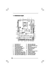
Motherboard Layout English 1 PS2_USB_PWR1 Jumper 15 USB 2.0 Header (USB6_7, Blue) 2 775-Pin CPU Socket 16 USB 2.0 Header (USB4_5, Blue) 3 North Bridge Controller 17 System Panel Header (PANEL1, Orange) 4 CPU Fan Connector (CPU_FAN1) 18 BIOS SPI... SATAII Connector (SATAII_2; Red) 27 OC 800 / FSB0 / FSB1 Jumper 14 Chassis Speaker Header (SPEAKER 1, 28 ATX 12V Connector (ATX12V1) Purple) 2 ASRock G31M-GS / G31M-S Motherboard Orange) 24 PCI Express x16 Slot (PCIE2) 11 Fourth SATAII Connector (SATAII_4; Yellow) 20 Floppy Connector (FLOPPY1) 6 ATX Power Connector (ATXPWR1) ...
Motherboard Layout English 1 PS2_USB_PWR1 Jumper 15 USB 2.0 Header (USB6_7, Blue) 2 775-Pin CPU Socket 16 USB 2.0 Header (USB4_5, Blue) 3 North Bridge Controller 17 System Panel Header (PANEL1, Orange) 4 CPU Fan Connector (CPU_FAN1) 18 BIOS SPI... SATAII Connector (SATAII_2; Red) 27 OC 800 / FSB0 / FSB1 Jumper 14 Chassis Speaker Header (SPEAKER 1, 28 ATX 12V Connector (ATX12V1) Purple) 2 ASRock G31M-GS / G31M-S Motherboard Orange) 24 PCI Express x16 Slot (PCIE2) 11 Fourth SATAII Connector (SATAII_4; Yellow) 20 Floppy Connector (FLOPPY1) 6 ATX Power Connector (ATXPWR1) ...
Quick Installation Guide
Page 9
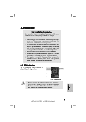
... 2.1 CPU Installation For the installation of the following precautions before touching any component, place it on the socket. To avoid damaging the motherboard components due to the motherboard, peripherals, and/or components. 2. Also remember... to the chassis, please do not touch the ICs. 4. When placing screws into the socket if above situation is any motherboard settings. 1. Installation Pre-installation Precautions Take note of Intel 775-LAND CPU...component. 5. Otherwise, the CPU will be seriously damaged. 9 ASRock G31M-GS / G31M-S Motherboard English
... 2.1 CPU Installation For the installation of the following precautions before touching any component, place it on the socket. To avoid damaging the motherboard components due to the motherboard, peripherals, and/or components. 2. Also remember... to the chassis, please do not touch the ICs. 4. When placing screws into the socket if above situation is any motherboard settings. 1. Installation Pre-installation Precautions Take note of Intel 775-LAND CPU...component. 5. Otherwise, the CPU will be seriously damaged. 9 ASRock G31M-GS / G31M-S Motherboard English
Quick Installation Guide
Page 10
... Pin1 orientation key notch orientation key notch Pin1 alignment key alignment key 775-LAND CPU 775-Pin Socket For proper inserting, please ensure to assist in removal. 10 ASRock G31M-GS / G31M-S Motherboard Step 1-3. Hold the CPU by the edges where are marked with IHS (Integrated Heat Sink...approximately 100 degrees. Step 1-2. Rotate the load plate to the orient keys. Carefully place the CPU into the socket by depressing down and out on center of the socket. Disengaging the lever by using a purely vertical motion. Insert the 775-LAND CPU: Step 2-1. Step 3....
... Pin1 orientation key notch orientation key notch Pin1 alignment key alignment key 775-LAND CPU 775-Pin Socket For proper inserting, please ensure to assist in removal. 10 ASRock G31M-GS / G31M-S Motherboard Step 1-3. Hold the CPU by the edges where are marked with IHS (Integrated Heat Sink...approximately 100 degrees. Step 1-2. Rotate the load plate to the orient keys. Carefully place the CPU into the socket by depressing down and out on center of the socket. Disengaging the lever by using a purely vertical motion. Insert the 775-LAND CPU: Step 2-1. Step 3....
Quick Installation Guide
Page 11
... Apply thermal interface material onto center of your CPU fan and heatsink. Place the heatsink onto the socket. Rotate the fastener clockwise, then press down on the socket surface. Step 4-3. Secure load lever with the motherboard throughholes. 1. This cap must be secured on... cannot be placed if returning the motherboard for 775-LAND CPU. Repeat with fan operation or contact other components. 11 ASRock G31M-GS / G31M-S Motherboard Step 4. Connect fan header with thumb to ensure cable does not interfere with remaining fasteners. Step 6. Secure excess...
... Apply thermal interface material onto center of your CPU fan and heatsink. Place the heatsink onto the socket. Rotate the fastener clockwise, then press down on the socket surface. Step 4-3. Secure load lever with the motherboard throughholes. 1. This cap must be secured on... cannot be placed if returning the motherboard for 775-LAND CPU. Repeat with fan operation or contact other components. 11 ASRock G31M-GS / G31M-S Motherboard Step 4. Connect fan header with thumb to ensure cable does not interfere with remaining fasteners. Step 6. Secure excess...
