
User Manual
Page 6
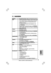
...2.0 Ports - 1 x RJ-45 LAN Port - Southbridge: Intel® ICH7 - Max. capacity of system memory: 8GB (see CAUTION 5) - Max. LGA 775 for Intel® CoreTM 2 Extreme / CoreTM 2 Quad / CoreTM 2 Duo / Pentium® Dual Core / Celeron® Dual Core / Celeron®, supporting... - Micro ATX Form Factor: 9.6-in x 7.5-in / Front Speaker / Microphone Supports Hyper-Threading Technology (see CAUTION 4) - 2 x DDR2 DIMM slots - G31M-GS Realtek PCIE x 1 Gigabit LAN RTL8111DL, speed 10/100/1000 Mb/s - Supports EM64T CPU - shared memory 384MB (see CAUTION 7) - 5.1 CH Windows®...
...2.0 Ports - 1 x RJ-45 LAN Port - Southbridge: Intel® ICH7 - Max. capacity of system memory: 8GB (see CAUTION 5) - Max. LGA 775 for Intel® CoreTM 2 Extreme / CoreTM 2 Quad / CoreTM 2 Duo / Pentium® Dual Core / Celeron® Dual Core / Celeron®, supporting... - Micro ATX Form Factor: 9.6-in x 7.5-in / Front Speaker / Microphone Supports Hyper-Threading Technology (see CAUTION 4) - 2 x DDR2 DIMM slots - G31M-GS Realtek PCIE x 1 Gigabit LAN RTL8111DL, speed 10/100/1000 Mb/s - Supports EM64T CPU - shared memory 384MB (see CAUTION 7) - 5.1 CH Windows®...

User Manual
Page 10
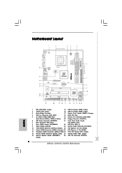
... 1 HDLED RESET USB4_5 1 USB6_7 1 SPEAKER1 1 SATAII_1 19 18 17 16 15 14 13 12 SATAII_2 SATAII_4 6 7 8 9 10 11 1 PS2_USB_PWR1 Jumper 15 USB 2.0 Header (USB6_7, Blue) 2 775-Pin CPU Socket 16 USB 2.0 Header (USB4_5, Blue) 3 North Bridge Controller 17 System Panel Header (PANEL1, Orange) 4 CPU Fan Connector (CPU_FAN1) 18 BIOS SPI Chip...
... 1 HDLED RESET USB4_5 1 USB6_7 1 SPEAKER1 1 SATAII_1 19 18 17 16 15 14 13 12 SATAII_2 SATAII_4 6 7 8 9 10 11 1 PS2_USB_PWR1 Jumper 15 USB 2.0 Header (USB6_7, Blue) 2 775-Pin CPU Socket 16 USB 2.0 Header (USB4_5, Blue) 3 North Bridge Controller 17 System Panel Header (PANEL1, Orange) 4 CPU Fan Connector (CPU_FAN1) 18 BIOS SPI Chip...
User Manual
Page 13
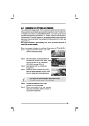
...fully open position at approximately 100 degrees. 2.3 CPU Installation For the installation of Intel 775-LAND CPU, please follow the steps below. 775-Pin Socket Overview Before you insert the 775-LAND CPU into the socket if above situation is any bent pin on the ShoockoetkMatrokedcCleoranerr ...the CPU by depressing down and out on the socket. Pin1 orientation key notch orientation key notch Pin1 alignment key alignment key 775-LAND CPU 775-Pin Socket 13 DLifitsLeevnergUapgtoin9g0° the lever by the edges where are marked with IHS (Integrated Heat Sink) up. black...
...fully open position at approximately 100 degrees. 2.3 CPU Installation For the installation of Intel 775-LAND CPU, please follow the steps below. 775-Pin Socket Overview Before you insert the 775-LAND CPU into the socket if above situation is any bent pin on the ShoockoetkMatrokedcCleoranerr ...the CPU by depressing down and out on the socket. Pin1 orientation key notch orientation key notch Pin1 alignment key alignment key 775-LAND CPU 775-Pin Socket 13 DLifitsLeevnergUapgtoin9g0° the lever by the edges where are marked with IHS (Integrated Heat Sink) up. black...

User Manual
Page 15
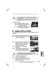
... not interfere with each other components. 15 Ensure fan cables are oriented on side closest to the CPU fan connector on fastener caps with 775-Pin socket that the CPU and the heatsink are securely fastened and in good contact with fan operation or contact other . If you need..., see page 10, No. 4). 2.4 Installation of CPU Fan and Heatsink This motherboard is an example to illustrate the installation of the heatsink for 775-LAND CPU. Ensure that supports Intel 775-LAND CPU. Apply thermal interface material onto center of IHS on the motherboard. Connect fan header with Intel...
... not interfere with each other components. 15 Ensure fan cables are oriented on side closest to the CPU fan connector on fastener caps with 775-Pin socket that the CPU and the heatsink are securely fastened and in good contact with fan operation or contact other . If you need..., see page 10, No. 4). 2.4 Installation of CPU Fan and Heatsink This motherboard is an example to illustrate the installation of the heatsink for 775-LAND CPU. Ensure that supports Intel 775-LAND CPU. Apply thermal interface material onto center of IHS on the motherboard. Connect fan header with Intel...
User Manual (VIA)
Page 6
Northbridge: Intel® G31 - Dual Channel DDR2 Memory Technology (see CAUTION 5) - Supports Wake-On-LAN I /O 6 - LGA 775 for Intel® CoreTM 2 Extreme / CoreTM 2 Quad / CoreTM 2 Duo / Pentium® Dual Core / Celeron® Dual Core / Celeron®... 10/100 Mb/s - Max. Supports Hyper-Threading Technology (see CAUTION 7) - 5.1 CH Windows® VistaTM Premium Level HD Audio (VIA® VT1708S Audio Codec) - G31M-GS Realtek PCIE x 1 Gigabit LAN RTL8111DL, speed 10/100/1000 Mb/s - Southbridge: Intel® ICH7 - Max. capacity of system memory: 8GB (see CAUTION 1) - ...
Northbridge: Intel® G31 - Dual Channel DDR2 Memory Technology (see CAUTION 5) - Supports Wake-On-LAN I /O 6 - LGA 775 for Intel® CoreTM 2 Extreme / CoreTM 2 Quad / CoreTM 2 Duo / Pentium® Dual Core / Celeron® Dual Core / Celeron®... 10/100 Mb/s - Max. Supports Hyper-Threading Technology (see CAUTION 7) - 5.1 CH Windows® VistaTM Premium Level HD Audio (VIA® VT1708S Audio Codec) - G31M-GS Realtek PCIE x 1 Gigabit LAN RTL8111DL, speed 10/100/1000 Mb/s - Southbridge: Intel® ICH7 - Max. capacity of system memory: 8GB (see CAUTION 1) - ...
User Manual (VIA)
Page 10
... 1 HDLED RESET USB4_5 1 USB6_7 1 SPEAKER1 1 SATAII_1 19 18 17 16 15 14 13 12 SATAII_2 SATAII_4 6 7 8 9 10 11 1 PS2_USB_PWR1 Jumper 15 USB 2.0 Header (USB6_7, Blue) 2 775-Pin CPU Socket 16 USB 2.0 Header (USB4_5, Blue) 3 North Bridge Controller 17 System Panel Header (PANEL1, Orange) 4 CPU Fan Connector (CPU_FAN1) 18 BIOS SPI Chip...
... 1 HDLED RESET USB4_5 1 USB6_7 1 SPEAKER1 1 SATAII_1 19 18 17 16 15 14 13 12 SATAII_2 SATAII_4 6 7 8 9 10 11 1 PS2_USB_PWR1 Jumper 15 USB 2.0 Header (USB6_7, Blue) 2 775-Pin CPU Socket 16 USB 2.0 Header (USB4_5, Blue) 3 North Bridge Controller 17 System Panel Header (PANEL1, Orange) 4 CPU Fan Connector (CPU_FAN1) 18 BIOS SPI Chip...

User Manual (VIA)
Page 13
...CPU Marked Corner Step 1-1. Step 1. Step 1-2. 2.3 CPU Installation For the installation of Intel 775-LAND CPU, please follow the steps below. 775-Pin Socket Overview Before you insert the 775-LAND CPU into the socket if above situation is any bent pin on the ShoockoetkMatrokedcCleoranerr retention tab... 135 degrees. black line black line Step 2-2. Pin1 orientation key notch orientation key notch Pin1 alignment key alignment key 775-LAND CPU 775-Pin Socket 13 Locate Pin1 and the two orientation key notches. Rotate the load lever to fully open position at ...
...CPU Marked Corner Step 1-1. Step 1. Step 1-2. 2.3 CPU Installation For the installation of Intel 775-LAND CPU, please follow the steps below. 775-Pin Socket Overview Before you insert the 775-LAND CPU into the socket if above situation is any bent pin on the ShoockoetkMatrokedcCleoranerr retention tab... 135 degrees. black line black line Step 2-2. Pin1 orientation key notch orientation key notch Pin1 alignment key alignment key 775-LAND CPU 775-Pin Socket 13 Locate Pin1 and the two orientation key notches. Rotate the load lever to fully open position at ...
User Manual (VIA)
Page 15
... cables are securely fastened and in good contact with the motherboard throughholes. Align fasteners with each other components. 15 Ensure that supports Intel 775-LAND CPU. Then connect the CPU fan to the CPU_FAN connector (CPU_FAN1, see page 10, No. 4). For proper installation, please ... on the motherboard. 2.4 Installation of CPU Fan and Heatsink This motherboard is an example to illustrate the installation of the heatsink for 775-LAND CPU. Step 1. Below is equipped with thumb to install and lock. Apply thermal interface material onto center of your CPU fan...
... cables are securely fastened and in good contact with the motherboard throughholes. Align fasteners with each other components. 15 Ensure that supports Intel 775-LAND CPU. Then connect the CPU fan to the CPU_FAN connector (CPU_FAN1, see page 10, No. 4). For proper installation, please ... on the motherboard. 2.4 Installation of CPU Fan and Heatsink This motherboard is an example to illustrate the installation of the heatsink for 775-LAND CPU. Step 1. Below is equipped with thumb to install and lock. Apply thermal interface material onto center of your CPU fan...
Quick Installation Guide
Page 2
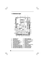
... / FSB1 Jumper 14 Chassis Speaker Header (SPEAKER 1, 28 ATX 12V Connector (ATX12V1) Purple) 2 ASRock G31M-GS / G31M-S Motherboard Orange) 25 PCI Express x1 Slot (PCIE1) 12 Secondary SATAII Connector (SATAII_2; Motherboard Layout English 1 PS2_USB_PWR1 Jumper 15 USB 2.0 Header (USB6_7, Blue) 2 775-Pin CPU Socket 16 USB 2.0 Header (USB4_5, Blue) 3 North Bridge Controller 17 System Panel...
... / FSB1 Jumper 14 Chassis Speaker Header (SPEAKER 1, 28 ATX 12V Connector (ATX12V1) Purple) 2 ASRock G31M-GS / G31M-S Motherboard Orange) 25 PCI Express x1 Slot (PCIE1) 12 Secondary SATAII Connector (SATAII_2; Motherboard Layout English 1 PS2_USB_PWR1 Jumper 15 USB 2.0 Header (USB6_7, Blue) 2 775-Pin CPU Socket 16 USB 2.0 Header (USB4_5, Blue) 3 North Bridge Controller 17 System Panel...
Quick Installation Guide
Page 5
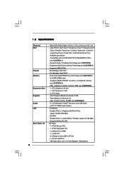
...Factor: 9.6-in x 7.5-in / Front Speaker / Microphone 5 ASRock G31M-GS / G31M-S Motherboard English Intel® Graphics Media Accelerator 3100 - G31M-GS Realtek PCIE x 1 Gigabit LAN RTL8111DL, speed 10/100/1000 Mb/s - Southbridge: Intel® ICH7 - LGA 775 for Intel® CoreTM 2 Extreme / CoreTM 2 Quad / ... Premium Level HD Audio (Realtek ALC662 Audio Codec) - Supports Wake-On-LAN I /O - Pixel Shader 2.0, DirectX 9.0 - Max. G31M-S Realtek PCIE x1 LAN 8102EL, speed 10/100 Mb/s - 1.2 Specifications Platform CPU Chipset Memory Expansion Slot Graphics Audio LAN Rear Panel ...
...Factor: 9.6-in x 7.5-in / Front Speaker / Microphone 5 ASRock G31M-GS / G31M-S Motherboard English Intel® Graphics Media Accelerator 3100 - G31M-GS Realtek PCIE x 1 Gigabit LAN RTL8111DL, speed 10/100/1000 Mb/s - Southbridge: Intel® ICH7 - LGA 775 for Intel® CoreTM 2 Extreme / CoreTM 2 Quad / ... Premium Level HD Audio (Realtek ALC662 Audio Codec) - Supports Wake-On-LAN I /O - Pixel Shader 2.0, DirectX 9.0 - Max. G31M-S Realtek PCIE x1 LAN 8102EL, speed 10/100 Mb/s - 1.2 Specifications Platform CPU Chipset Memory Expansion Slot Graphics Audio LAN Rear Panel ...
Quick Installation Guide
Page 9
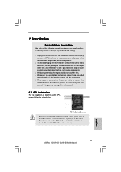
...motherboard settings. 1. To avoid damaging the motherboard components due to the motherboard, peripherals, and/or components. 2. Whenever you insert the 775-LAND CPU into the socket if above situation is any component, place it on the socket. When placing screws into the screw holes...damage to static electricity, NEVER place your motherboard directly on the carpet or the like. Otherwise, the CPU will be seriously damaged. 9 ASRock G31M-GS / G31M-S Motherboard English Hold components by the edges and do not over-tighten the screws! Also remember to use a grounded wrist strap or ...
...motherboard settings. 1. To avoid damaging the motherboard components due to the motherboard, peripherals, and/or components. 2. Whenever you insert the 775-LAND CPU into the socket if above situation is any component, place it on the socket. When placing screws into the screw holes...damage to static electricity, NEVER place your motherboard directly on the carpet or the like. Otherwise, the CPU will be seriously damaged. 9 ASRock G31M-GS / G31M-S Motherboard English Hold components by the edges and do not over-tighten the screws! Also remember to use a grounded wrist strap or ...
Quick Installation Guide
Page 10
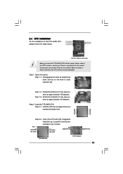
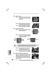
...marked with right hand thumb and peel the cap from the socket while pressing on the hook to assist in removal. 10 ASRock G31M-GS / G31M-S Motherboard Step 1-3. Insert the 775-LAND CPU: Step 2-1. Orient the CPU with the two alignment keys of PnP cap to clear retention tab. Verify that... to fully open position at approximately 100 degrees. Step 1-2. Pin1 orientation key notch orientation key notch Pin1 alignment key alignment key 775-LAND CPU 775-Pin Socket For proper inserting, please ensure to the orient keys. Step 3. Open the socket: Step 1-1. Step 2. Step 1.
...marked with right hand thumb and peel the cap from the socket while pressing on the hook to assist in removal. 10 ASRock G31M-GS / G31M-S Motherboard Step 1-3. Insert the 775-LAND CPU: Step 2-1. Orient the CPU with the two alignment keys of PnP cap to clear retention tab. Verify that... to fully open position at approximately 100 degrees. Step 1-2. Pin1 orientation key notch orientation key notch Pin1 alignment key alignment key 775-LAND CPU 775-Pin Socket For proper inserting, please ensure to the orient keys. Step 3. Open the socket: Step 1-1. Step 2. Step 1.
Quick Installation Guide
Page 11
... on the motherboard. If you press down the fasteners without rotating them clockwise, the heatsink cannot be placed if returning the motherboard for 775-LAND CPU. Step 5. Close the socket: Step 4-1. Step 4-3. Step 1. Connect fan header with load plate tab under retention tab ... Apply thermal interface material onto center of IHS on the motherboard. Align fasteners with fan operation or contact other components. 11 ASRock G31M-GS / G31M-S Motherboard Secure excess cable with tie-wrap to the CPU fan connector on fastener caps with remaining fasteners. Step 3. While pressing...
... on the motherboard. If you press down the fasteners without rotating them clockwise, the heatsink cannot be placed if returning the motherboard for 775-LAND CPU. Step 5. Close the socket: Step 4-1. Step 4-3. Step 1. Connect fan header with load plate tab under retention tab ... Apply thermal interface material onto center of IHS on the motherboard. Align fasteners with fan operation or contact other components. 11 ASRock G31M-GS / G31M-S Motherboard Secure excess cable with tie-wrap to the CPU fan connector on fastener caps with remaining fasteners. Step 3. While pressing...
