User Manual
Page 2
...manual. In no responsibility for loss of profits, loss of business, loss of data, interruption of business and the like), even if ASRock has been advised of the possibility of such damages arising from any defect or error in the manual or product. When you discard ...on this manual, ASRock does not provide warranty of any kind, either expressed or implied, including but not limited to the implied warranties or conditions of merchantability or fitness for identification or explanation and to the owners' benefit, without intent to the contents of this motherboard contains Perchlorate, a...
...manual. In no responsibility for loss of profits, loss of business, loss of data, interruption of business and the like), even if ASRock has been advised of the possibility of such damages arising from any defect or error in the manual or product. When you discard ...on this manual, ASRock does not provide warranty of any kind, either expressed or implied, including but not limited to the implied warranties or conditions of merchantability or fitness for identification or explanation and to the owners' benefit, without intent to the contents of this motherboard contains Perchlorate, a...
User Manual
Page 3
Contents 1 Introduction 5 1.1 Package Contents 5 1.2 Specifications 6 1.3 Motherboard Layout 10 1.4 I/O Panel 11 2 Installation 12 2.1 Screw Holes 12 2.2 Pre-installation Precautions 12 2.3 CPU Installation 13 2.4 Installation of Heatsink and CPU fan 15 2.5 Installation of ...
Contents 1 Introduction 5 1.1 Package Contents 5 1.2 Specifications 6 1.3 Motherboard Layout 10 1.4 I/O Panel 11 2 Installation 12 2.1 Screw Holes 12 2.2 Pre-installation Precautions 12 2.3 CPU Installation 13 2.4 Installation of Heatsink and CPU fan 15 2.5 Installation of ...
User Manual
Page 5
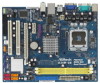
... cards and CPU support lists on ASRock website without notice. In this motherboard, please visit our website for purchasing ASRock G31M-GS / G31M-S motherboard, a reliable motherboard produced under ASRock's consistently stringent quality control. www.asrock.com/support/index.asp 1.1 Package Contents ASRock G31M-GS / G31M-S Motherboard (Micro ATX Form Factor: 9.6-in x 7.5-in, 24.4 cm x 19.1 cm) ASRock G31M-GS / G31M-S Quick Installation Guide ASRock G31M-GS / G31M-S Support CD One 80-conductor Ultra...
... cards and CPU support lists on ASRock website without notice. In this motherboard, please visit our website for purchasing ASRock G31M-GS / G31M-S motherboard, a reliable motherboard produced under ASRock's consistently stringent quality control. www.asrock.com/support/index.asp 1.1 Package Contents ASRock G31M-GS / G31M-S Motherboard (Micro ATX Form Factor: 9.6-in x 7.5-in, 24.4 cm x 19.1 cm) ASRock G31M-GS / G31M-S Quick Installation Guide ASRock G31M-GS / G31M-S Support CD One 80-conductor Ultra...
User Manual
Page 8
... this situation, PCIE frequency will operate in the BIOS, applying Untied Overclocking Technology, or using the thirdparty overclocking tools. About the setting of ASRock OC Tuner. This motherboard supports Untied Overclocking Technology. Please visit our website for proper installation. 5. We are not responsible for possible damage caused by the chipset vendor and...
... this situation, PCIE frequency will operate in the BIOS, applying Untied Overclocking Technology, or using the thirdparty overclocking tools. About the setting of ASRock OC Tuner. This motherboard supports Untied Overclocking Technology. Please visit our website for proper installation. 5. We are not responsible for possible damage caused by the chipset vendor and...
User Manual
Page 9
... the heatsink when you resume the system, please check if the CPU fan on the motherboard functions properly and unplug the power cord, then plug it back again. ASRock website: http://www.asrock.com 12. 11. In other than the recommended CPU bus frequencies may cause the instability... of Intelligent Energy Saver. Although this motherboard offers stepless control, it is not recommended to provide exceptional power...
... the heatsink when you resume the system, please check if the CPU fan on the motherboard functions properly and unplug the power cord, then plug it back again. ASRock website: http://www.asrock.com 12. 11. In other than the recommended CPU bus frequencies may cause the instability... of Intelligent Energy Saver. Although this motherboard offers stepless control, it is not recommended to provide exceptional power...
User Manual
Page 10
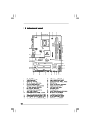
... Bridge Controller 23 Internal Audio Connector: CD1 (Black) 10 Third SATAII Connector (SATAII_3; Red) 26 Print Port Header (LPT1, Purple) 13 Primary SATAII Connector (SATAII_1; 1.3 Motherboard Layout 1 2 34 5 19.1cm (7.5 in) 1 PS2_USB_PWR1 CPU_FAN1 PS2 Mouse PS2 Keyboard COM1 FSB1600 DDR2 800 Dual Channel DDRII_1 (64 bit, 240-piFnSmBod8ul0e)0 DDRII_2 (64 bit...
... Bridge Controller 23 Internal Audio Connector: CD1 (Black) 10 Third SATAII Connector (SATAII_3; Red) 26 Print Port Header (LPT1, Purple) 13 Primary SATAII Connector (SATAII_1; 1.3 Motherboard Layout 1 2 34 5 19.1cm (7.5 in) 1 PS2_USB_PWR1 CPU_FAN1 PS2 Mouse PS2 Keyboard COM1 FSB1600 DDR2 800 Dual Channel DDRII_1 (64 bit, 240-piFnSmBod8ul0e)0 DDRII_2 (64 bit...
User Manual
Page 12
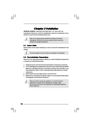
To avoid damaging the motherboard components due to motherboard components. 2.1 Screw Holes Place screws into it on the carpet or the like. Chapter 2 Installation G31M-GS / G31M-S is detached from the wall socket before you handle components. 3. Failure to do so may cause...may cause severe damage to unplug the power cord before you uninstall any motherboard settings. 1. Before you install the motherboard, study the configuration of the following precautions before installing or removing the motherboard. Unplug the power cord from the power supply. Before you install or...
To avoid damaging the motherboard components due to motherboard components. 2.1 Screw Holes Place screws into it on the carpet or the like. Chapter 2 Installation G31M-GS / G31M-S is detached from the wall socket before you handle components. 3. Failure to do so may cause...may cause severe damage to unplug the power cord before you uninstall any motherboard settings. 1. Before you install the motherboard, study the configuration of the following precautions before installing or removing the motherboard. Unplug the power cord from the power supply. Before you install or...

User Manual
Page 14
... the PnP cap. 2. Carefully place the CPU into the socket by using a purely vertical motion. Step 4. Step 4-2. This cap must be placed if returning the motherboard for after service. Step 2-4. Verify that the CPU is recommended to use the cap tab to assist in removal. 1. For proper inserting, please ensure to...
... the PnP cap. 2. Carefully place the CPU into the socket by using a purely vertical motion. Step 4. Step 4-2. This cap must be placed if returning the motherboard for after service. Step 2-4. Verify that the CPU is recommended to use the cap tab to assist in removal. 1. For proper inserting, please ensure to...
User Manual
Page 15
...fastener clockwise, then press down the fasteners without rotating them clockwise, the heatsink cannot be secured on the motherboard. 2.4 Installation of CPU Fan and Heatsink This motherboard is an example to illustrate the installation of the heatsink for 775-LAND CPU. Before you installed the heatsink..., you press down on the motherboard (CPU_FAN1, see page 10, No. 4). Step 2. Repeat with the motherboard throughholes. If you need to spray thermal interface material between the CPU and the heatsink to improve...
...fastener clockwise, then press down the fasteners without rotating them clockwise, the heatsink cannot be secured on the motherboard. 2.4 Installation of CPU Fan and Heatsink This motherboard is an example to illustrate the installation of the heatsink for 775-LAND CPU. Before you installed the heatsink..., you press down on the motherboard (CPU_FAN1, see page 10, No. 4). Step 2. Repeat with the motherboard throughholes. If you need to spray thermal interface material between the CPU and the heatsink to improve...
User Manual
Page 16
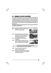
...DDR memory module into the slot at incorrect orientation. It is properly seated. 16 Step 3. Installing a DIMM Please make sure to the motherboard and the DIMM if you install only one correct orientation. Step 2. Firmly insert the DIMM into the slot until the retaining clips at... notch break The DIMM only fits in the DDR2 DIMM slots to activate the Dual Channel Memory Technology. 2.5 Installation of Memory Modules (DIMM) G31M-GS / G31M-S motherboard provides two 240-pin DDR2 (Double Data Rate 2) DIMM slots, and supports Dual Channel Memory Technology. Step 1. Align a DIMM on the ...
...DDR memory module into the slot at incorrect orientation. It is properly seated. 16 Step 3. Installing a DIMM Please make sure to the motherboard and the DIMM if you install only one correct orientation. Step 2. Firmly insert the DIMM into the slot until the retaining clips at... notch break The DIMM only fits in the DDR2 DIMM slots to activate the Dual Channel Memory Technology. 2.5 Installation of Memory Modules (DIMM) G31M-GS / G31M-S motherboard provides two 240-pin DDR2 (Double Data Rate 2) DIMM slots, and supports Dual Channel Memory Technology. Step 1. Align a DIMM on the ...
User Manual
Page 17
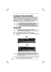
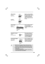
... slots are 2 PCI slots and 2 PCI Express slots on the slot. Installing an expansion card Step 1. PCIE2 (PCIE x16 slot) is completely seated on this motherboard. Before installing the expansion card, please make necessary hardware settings for PCI Express cards with x1 lane width cards, such as Gigabit LAN card, SATA2...
... slots are 2 PCI slots and 2 PCI Express slots on the slot. Installing an expansion card Step 1. PCIE2 (PCIE x16 slot) is completely seated on this motherboard. Before installing the expansion card, please make necessary hardware settings for PCI Express cards with x1 lane width cards, such as Gigabit LAN card, SATA2...
User Manual
Page 19
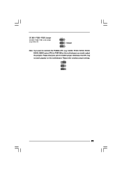
OC 800 / FSB0 / FSB1 Jumper (OC 800 / FSB0 / FSB1, 3-pin jumper, see p.10 No. 27) 1_2 1_2 Default 1_2 Note: If you need to adjust the jumpers. Cel400, E1000, E2000, E4000, E5000, E6000 series CPU) to FSB1066 on this motherboard, you want to below jumper settings. 2_3 1_2 1_2 19 Please refer to overclock the FSB800-CPU (e.g. Otherwise, the CPU may not work properly on this motherboard. Please short pin2, pin3 for OC800 jumper.
OC 800 / FSB0 / FSB1 Jumper (OC 800 / FSB0 / FSB1, 3-pin jumper, see p.10 No. 27) 1_2 1_2 Default 1_2 Note: If you need to adjust the jumpers. Cel400, E1000, E2000, E4000, E5000, E6000 series CPU) to FSB1066 on this motherboard, you want to below jumper settings. 2_3 1_2 1_2 19 Please refer to overclock the FSB800-CPU (e.g. Otherwise, the CPU may not work properly on this motherboard. Please short pin2, pin3 for OC800 jumper.
User Manual
Page 20
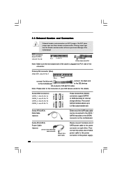
...Primary IDE connector (Blue) (39-pin IDE1, see p.10 No. 20) Pin1 FLOPPY1 the red-striped side to the power connector on the motherboard. Do NOT place jumper caps over the headers and connectors will cause permanent damage of your IDE device vendor for internal storage devices. FDD connector... (33-pin FLOPPY1) (see p.10 No. 7) PIN1 IDE1 connect the blue end connect the black end to the motherboard to the IDE devices 80-conductor ATA 66/100 cable Note: Please refer to the power connector of the connector. Serial ATA (SATA) Data ...
...Primary IDE connector (Blue) (39-pin IDE1, see p.10 No. 20) Pin1 FLOPPY1 the red-striped side to the power connector on the motherboard. Do NOT place jumper caps over the headers and connectors will cause permanent damage of your IDE device vendor for internal storage devices. FDD connector... (33-pin FLOPPY1) (see p.10 No. 7) PIN1 IDE1 connect the blue end connect the black end to the motherboard to the IDE devices 80-conductor ATA 66/100 cable Note: Please refer to the power connector of the connector. Serial ATA (SATA) Data ...
User Manual
Page 21
... and chassis manual to MIC2_L. C. B. Each USB 2.0 header can support two USB 2.0 ports. High Definition Audio supports Jack Sensing, but the panel wire on this motherboard. If you to receive stereo audio input CD1 from sound sources such as below: A. Front Panel Audio Header (9-pin HD_AUDIO1) (see p.10 No. 21) GND...
... and chassis manual to MIC2_L. C. B. Each USB 2.0 header can support two USB 2.0 ports. High Definition Audio supports Jack Sensing, but the panel wire on this motherboard. If you to receive stereo audio input CD1 from sound sources such as below: A. Front Panel Audio Header (9-pin HD_AUDIO1) (see p.10 No. 21) GND...
User Manual
Page 23
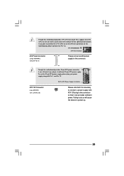
... function. To use the 20-pin ATX power supply, please plug your power supply along with ATX 12V plug to power up. 23 Though this motherboard provides 24-pin ATX power connector, 12 24 it is necessary to connect a power supply with Pin 1 and Pin 13. 20-Pin ATX Power Supply... p.10 No. 28) Please note that it can work if you plan to connect the 3-Pin CPU fan to the CPU fan connector on this motherboard, please connect it to this connector. 1 13 Though this motherboard provides 4-Pin CPU fan (Quiet Fan) support, the 3-Pin CPU fan still can provides sufficient power.
... function. To use the 20-pin ATX power supply, please plug your power supply along with ATX 12V plug to power up. 23 Though this motherboard provides 24-pin ATX power connector, 12 24 it is necessary to connect a power supply with Pin 1 and Pin 13. 20-Pin ATX Power Supply... p.10 No. 28) Please note that it can work if you plan to connect the 3-Pin CPU fan to the CPU fan connector on this motherboard, please connect it to this connector. 1 13 Though this motherboard provides 4-Pin CPU fan (Quiet Fan) support, the 3-Pin CPU fan still can provides sufficient power.
User Manual
Page 25
... the support CD to install those required drivers. 2 . 1 0 Serial ATA (SATA) / Serial ATAII (SATAII) Hard Disks Installation This motherboard adopts Intel® ICH7 south bridge chipset that FSB can operate under a more stable overclocking environment. Please follow the order from [Auto] to...cable to fixed PCI / PCIE buses. Then, the drivers compatible to your system can work properly. 2.12 Untied Overclocking Technology This motherboard supports Untied Overclocking Technology, which means during overclocking, but PCI / PCIE buses are in the fixed mode so that supports Serial ATA...
... the support CD to install those required drivers. 2 . 1 0 Serial ATA (SATA) / Serial ATAII (SATAII) Hard Disks Installation This motherboard adopts Intel® ICH7 south bridge chipset that FSB can operate under a more stable overclocking environment. Please follow the order from [Auto] to...cable to fixed PCI / PCIE buses. Then, the drivers compatible to your system can work properly. 2.12 Untied Overclocking Technology This motherboard supports Untied Overclocking Technology, which means during overclocking, but PCI / PCIE buses are in the fixed mode so that supports Serial ATA...

User Manual
Page 26
... (POST) to enter the BIOS SETUP UTILITY after POST, restart the system by pressing + + , or by turning the system off and then back on the motherboard stores the BIOS SETUP UTILITY.
... (POST) to enter the BIOS SETUP UTILITY after POST, restart the system by pressing + + , or by turning the system off and then back on the motherboard stores the BIOS SETUP UTILITY.
User Manual
Page 31
... not support Intel (R) Virtualization Technology. Ratio CMOS Setting If the ratio status is unlocked, you changing the ratio value of this motherboard. Enhance Halt State All processors support the Halt State (C1). The C1 state is an enhancement to execute code. CPU Thermal ... option " Intel (R) SpeedStep(tm) tech." Boot Failure Guard Enable or disable the feature of the system caches. in advance. When this motherboard. This option will be [Auto] for better system stability. No-Excute Memory Protection No-Execution (NX) Memory Protection Technology is supported through ...
... not support Intel (R) Virtualization Technology. Ratio CMOS Setting If the ratio status is unlocked, you changing the ratio value of this motherboard. Enhance Halt State All processors support the Halt State (C1). The C1 state is an enhancement to execute code. CPU Thermal ... option " Intel (R) SpeedStep(tm) tech." Boot Failure Guard Enable or disable the feature of the system caches. in advance. When this motherboard. This option will be [Auto] for better system stability. No-Excute Memory Protection No-Execution (NX) Memory Protection Technology is supported through ...
User Manual
Page 32
...] if using Microsoft® Windows® XP, or Linux kernel version 2.4.18 or higher. Set to enable power savings. The default value is selected, the motherboard will detect the memory module(s) inserted and assigns appropriate frequency automatically. If you install Windows® XP and select [Auto], you install Windows® VistaTM...
...] if using Microsoft® Windows® XP, or Linux kernel version 2.4.18 or higher. Set to enable power savings. The default value is selected, the motherboard will detect the memory module(s) inserted and assigns appropriate frequency automatically. If you install Windows® XP and select [Auto], you install Windows® VistaTM...
User Manual
Page 33
... is cooperatively using this option is allocated to [Enabled]. Configuration options: [Onboard], [PCI] and [PCI Express]. the onboard VGA will allow better tolerance for the motherboard through efficient memory utilization. If you install VGA card; DVMT Mode Select Use this item to adjust DVMT mode. In Fixed mode, a fixed-size fragment...
... is cooperatively using this option is allocated to [Enabled]. Configuration options: [Onboard], [PCI] and [PCI Express]. the onboard VGA will allow better tolerance for the motherboard through efficient memory utilization. If you install VGA card; DVMT Mode Select Use this item to adjust DVMT mode. In Fixed mode, a fixed-size fragment...


