
User Manual
Page 2
...for backup purpose, without written consent of merchantability or fitness for a particular purpose. With respect to the contents of this motherboard contains Perchlorate, a toxic substance controlled in the manual or product. This device complies with Part 15 of their respective companies,...only and subject to the following two conditions: (1) this device may not cause harmful interference, and (2) this manual. ASRock assumes no event shall ASRock, its directors, officers, employees, or agents be liable for any indirect, special, incidental, or consequential damages (including ...
...for backup purpose, without written consent of merchantability or fitness for a particular purpose. With respect to the contents of this motherboard contains Perchlorate, a toxic substance controlled in the manual or product. This device complies with Part 15 of their respective companies,...only and subject to the following two conditions: (1) this device may not cause harmful interference, and (2) this manual. ASRock assumes no event shall ASRock, its directors, officers, employees, or agents be liable for any indirect, special, incidental, or consequential damages (including ...
User Manual
Page 3
Contents 1 Introduction 5 1.1 Package Contents 5 1.2 Specifications 6 1.3 Motherboard Layout 10 1.4 I/O Panel (G31M-GS 11 1.5 I/O Panel (G31M-S 12 2 Installation 13 2.1 Screw Holes 13 2.2 Pre-installation Precautions 13 2.3 CPU Installation 14 2.4 Installation of Heatsink and CPU fan 16 2.5 Installation of Memory Modules (DIMM ...
Contents 1 Introduction 5 1.1 Package Contents 5 1.2 Specifications 6 1.3 Motherboard Layout 10 1.4 I/O Panel (G31M-GS 11 1.5 I/O Panel (G31M-S 12 2 Installation 13 2.1 Screw Holes 13 2.2 Pre-installation Precautions 13 2.3 CPU Installation 14 2.4 Installation of Heatsink and CPU fan 16 2.5 Installation of Memory Modules (DIMM ...
User Manual
Page 5
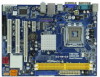
... case any modifications of this manual, chapter 1 and 2 contain introduction of the Support CD. www.asrock.com/support/index.asp 1.1 Package Contents ASRock G31M-GS / G31M-S Motherboard (Micro ATX Form Factor: 9.6-in x 7.2-in, 24.4 cm x 18.3 cm) ASRock G31M-GS / G31M-S Quick Installation Guide ASRock G31M-GS / G31M-S Support CD One 80-conductor Ultra ATA 66/100 IDE Ribbon Cable (Optional) One Serial ATA...
... case any modifications of this manual, chapter 1 and 2 contain introduction of the Support CD. www.asrock.com/support/index.asp 1.1 Package Contents ASRock G31M-GS / G31M-S Motherboard (Micro ATX Form Factor: 9.6-in x 7.2-in, 24.4 cm x 18.3 cm) ASRock G31M-GS / G31M-S Quick Installation Guide ASRock G31M-GS / G31M-S Support CD One 80-conductor Ultra ATA 66/100 IDE Ribbon Cable (Optional) One Serial ATA...

User Manual
Page 8
... disk to SATAII connector, please read the "SATAII Hard Disk Setup Guide" on page 25 to SATAII mode. CAUTION! 1. This motherboard supports Dual Channel Memory Technology. It should be done at your SATAII hard disk drive to adjust your own risk and expense. Please...", please check page 32. 3. The maximum shared memory size is subject to 120MHz. Overclocking may be overclocked to change. This motherboard supports Untied Overclocking Technology. Before you also need to adjust the jumpers. Power Management for possible damage caused by the chipset vendor and...
... disk to SATAII connector, please read the "SATAII Hard Disk Setup Guide" on page 25 to SATAII mode. CAUTION! 1. This motherboard supports Dual Channel Memory Technology. It should be done at your SATAII hard disk drive to adjust your own risk and expense. Please...", please check page 32. 3. The maximum shared memory size is subject to 120MHz. Overclocking may be overclocked to change. This motherboard supports Untied Overclocking Technology. Before you also need to adjust the jumpers. Power Management for possible damage caused by the chipset vendor and...
User Manual
Page 9
...than the recommended CPU bus frequencies may cause the instability of ASRock OC Tuner. While CPU overheat is a revolutionary technology that the USB flash drive or hard drive must meet EuP standard, an EuP ready motherboard and an EuP ready power supply are required. According to ... if the CPU fan on the motherboard functions properly and unplug the power cord, then plug it is a BIOS flash utility embedded in off mode condition. ASRock website: http://www.asrock.com 11. Please be under 100 mA current consumption. ASRock Instant Flash is not recommended to update...
...than the recommended CPU bus frequencies may cause the instability of ASRock OC Tuner. While CPU overheat is a revolutionary technology that the USB flash drive or hard drive must meet EuP standard, an EuP ready motherboard and an EuP ready power supply are required. According to ... if the CPU fan on the motherboard functions properly and unplug the power cord, then plug it is a BIOS flash utility embedded in off mode condition. ASRock website: http://www.asrock.com 11. Please be under 100 mA current consumption. ASRock Instant Flash is not recommended to update...

User Manual
Page 10
1.3 Motherboard Layout 29 COM1 PS2 Mouse PS2 Keyboard 1 2 34 5 18.3cm (7.2 in) 1 PS2_USB_PWR1 CPU_FAN1 ATX12V1 VGA1 LPT1 1 Top: Line In Center: Line Out Bottom: Mic In ...
1.3 Motherboard Layout 29 COM1 PS2 Mouse PS2 Keyboard 1 2 34 5 18.3cm (7.2 in) 1 PS2_USB_PWR1 CPU_FAN1 ATX12V1 VGA1 LPT1 1 Top: Line In Center: Line Out Bottom: Mic In ...

User Manual
Page 13
... damage to you uninstall any component, place it . Chapter 2 Installation G31M-GS / G31M-S is detached from the wall socket before touching any component. 2. Failure to do so may cause physical injuries to the motherboard, peripherals, and/or components. 13 To avoid damaging the motherboard components due to static electricity, NEVER place your chassis to unplug...
... damage to you uninstall any component, place it . Chapter 2 Installation G31M-GS / G31M-S is detached from the wall socket before touching any component. 2. Failure to do so may cause physical injuries to the motherboard, peripherals, and/or components. 13 To avoid damaging the motherboard components due to static electricity, NEVER place your chassis to unplug...
User Manual
Page 15
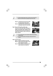
... tab of the socket. Step 2-4. Carefully place the CPU into the socket by using a purely vertical motion. This cap must be placed if returning the motherboard for after service. Rotate the load plate onto the IHS. Step 4-3. Remove PnP Cap (Pick and Place Cap): Use your left hand index finger and...
... tab of the socket. Step 2-4. Carefully place the CPU into the socket by using a purely vertical motion. This cap must be placed if returning the motherboard for after service. Rotate the load plate onto the IHS. Step 4-3. Remove PnP Cap (Pick and Place Cap): Use your left hand index finger and...
User Manual
Page 16
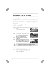
.... Below is equipped with 775-Pin socket that the CPU and the heatsink are oriented on side closest to the CPU fan connector on the motherboard (CPU_FAN1, see page 10, No. 4). Place the heatsink onto the socket. Align fasteners with Intel 775-LAND CPU to dissipate heat. Step ...other . Step 4. Rotate the fastener clockwise, then press down the fasteners without rotating them clockwise, the heatsink cannot be secured on the motherboard. Then connect the CPU fan to the CPU_FAN connector (CPU_FAN1, see page 10, No. 4). Step 3. Repeat with the CPU fan connector on ...
.... Below is equipped with 775-Pin socket that the CPU and the heatsink are oriented on side closest to the CPU fan connector on the motherboard (CPU_FAN1, see page 10, No. 4). Place the heatsink onto the socket. Align fasteners with Intel 775-LAND CPU to dissipate heat. Step ...other . Step 4. Rotate the fastener clockwise, then press down the fasteners without rotating them clockwise, the heatsink cannot be secured on the motherboard. Then connect the CPU fan to the CPU_FAN connector (CPU_FAN1, see page 10, No. 4). Step 3. Repeat with the CPU fan connector on ...

User Manual
Page 17
... you force the DIMM into DDR2 slot; Firmly insert the DIMM into the slot until the retaining clips at single channel mode. 1. otherwise, this motherboard and DIMM may be damaged. 2. 2.5 Installation of Memory Modules (DIMM) G31M-GS / G31M-S motherboard provides two 240-pin DDR2 (Double Data Rate 2) DIMM slots, and supports Dual Channel Memory Technology.
... you force the DIMM into DDR2 slot; Firmly insert the DIMM into the slot until the retaining clips at single channel mode. 1. otherwise, this motherboard and DIMM may be damaged. 2. 2.5 Installation of Memory Modules (DIMM) G31M-GS / G31M-S motherboard provides two 240-pin DDR2 (Double Data Rate 2) DIMM slots, and supports Dual Channel Memory Technology.
User Manual
Page 18
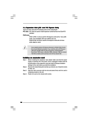
... an expansion card Step 1. Fasten the card to install expansion cards that you start the installation. PCIE2 (PCIE x16 slot) is completely seated on this motherboard. Keep the screws for PCI Express cards with screws. 18 Step 4. Step 2. PCI slots: PCI slots are 2 PCI slots and 2 PCI Express slots on the...
... an expansion card Step 1. Fasten the card to install expansion cards that you start the installation. PCIE2 (PCIE x16 slot) is completely seated on this motherboard. Keep the screws for PCI Express cards with screws. 18 Step 4. Step 2. PCI slots: PCI slots are 2 PCI slots and 2 PCI Express slots on the...
User Manual
Page 19
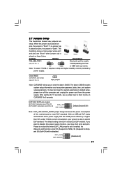
...Note: CLRCMOS1 allows you to default setup, please turn off the computer and unplug the power cord from the power supply. With an ASRock EuP ready motherboard and a power supply that when EUP_LAN jumper is placed on these 2 pins. 2.7 Jumpers Setup The illustration shows how jumpers are "Short... Default (Enable EuP) Note: EUP_LAN and EUP_AUDIO jumper design decreases the power consumption of this power saving function, you want to disable this motherboard to short 2 pins on pins, the jumper is EuP enabled. If no jumper cap is placed on CLRCMOS1 for PS/2 +5V +5VSB...
...Note: CLRCMOS1 allows you to default setup, please turn off the computer and unplug the power cord from the power supply. With an ASRock EuP ready motherboard and a power supply that when EUP_LAN jumper is placed on these 2 pins. 2.7 Jumpers Setup The illustration shows how jumpers are "Short... Default (Enable EuP) Note: EUP_LAN and EUP_AUDIO jumper design decreases the power consumption of this power saving function, you want to disable this motherboard to short 2 pins on pins, the jumper is EuP enabled. If no jumper cap is placed on CLRCMOS1 for PS/2 +5V +5VSB...
User Manual
Page 20
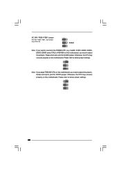
... jumpers. Please short pin2, pin3 for OC800 jumper. Otherwise, the CPU may not work properly on this motherboard. Please refer to below jumper settings. 2_3 1_2 1_2 Note: If you adopt FSB1600-CPU on this motherboard, you need to overclock the FSB800-CPU (e.g. Cel400, E1000, E2000, E4000, E5000, E6000 series CPU) ...to FSB1066 on this motherboard, you need to below jumper settings. 2_3 1_2 1_2 20 OC 800 / FSB0 / FSB1 Jumper (OC 800 / FSB0 / FSB1, 3-pin jumper, see p.10 No. 28)...
... jumpers. Please short pin2, pin3 for OC800 jumper. Otherwise, the CPU may not work properly on this motherboard. Please refer to below jumper settings. 2_3 1_2 1_2 Note: If you adopt FSB1600-CPU on this motherboard, you need to overclock the FSB800-CPU (e.g. Cel400, E1000, E2000, E4000, E5000, E6000 series CPU) ...to FSB1066 on this motherboard, you need to below jumper settings. 2_3 1_2 1_2 20 OC 800 / FSB0 / FSB1 Jumper (OC 800 / FSB0 / FSB1, 3-pin jumper, see p.10 No. 28)...

User Manual
Page 21
...see p.10 No. 7) PIN1 IDE1 connect the blue end connect the black end to the motherboard to the IDE devices 80-conductor ATA 66/100 cable Note: Please refer to the instruction of the motherboard! Serial ATA (SATA) Power Cable (Optional) connect to the SATA HDD power connector connect ...to the power connector on the motherboard. FDD connector (33-pin FLOPPY1) (see p.10, No. 11) SATAII_1 Serial ATA (SATA) Data Cable (Optional) SATAII_2 SATAII_3 SATAII_4 These Serial ATAII (SATAII...
...see p.10 No. 7) PIN1 IDE1 connect the blue end connect the black end to the motherboard to the IDE devices 80-conductor ATA 66/100 cable Note: Please refer to the instruction of the motherboard! Serial ATA (SATA) Power Cable (Optional) connect to the SATA HDD power connector connect ...to the power connector on the motherboard. FDD connector (33-pin FLOPPY1) (see p.10, No. 11) SATAII_1 Serial ATA (SATA) Data Cable (Optional) SATAII_2 SATAII_3 SATAII_4 These Serial ATAII (SATAII...
User Manual
Page 22
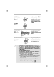
... PE SPD3 SLCT SPD2 SPD1 SPD0 STB# This is an interface for AC'97 audio panel. F. MIC_RET and OUT_RET are two USB 2.0 headers on this motherboard. USB 2.0 Headers (9-pin USB6_7) (see p.10 No. 16) (9-pin USB4_5) (see p.10 No. 17) USB_PWR P-7 P+7 GND DUMMY 1 GND P+6 P-6 USB_PWR USB_PWR P-5 P+5 GND DUMMY Besides four default...
... PE SPD3 SLCT SPD2 SPD1 SPD0 STB# This is an interface for AC'97 audio panel. F. MIC_RET and OUT_RET are two USB 2.0 headers on this motherboard. USB 2.0 Headers (9-pin USB6_7) (see p.10 No. 16) (9-pin USB4_5) (see p.10 No. 17) USB_PWR P-7 P+7 GND DUMMY 1 GND P+6 P-6 USB_PWR USB_PWR P-5 P+5 GND DUMMY Besides four default...

User Manual
Page 23
... portion. Chassis Fan Connector (3-pin CHA_FAN1) (see p.10 No. 18) GND +12V CHA_FAN_SPEED Please connect a chassis fan cable to this motherboard, please connect it to the ground pin. Though this connector and match the black wire to Pin 1-3. If you want to hear your voice...12) Chassis Speaker Header (4-pin SPEAKER 1) (see p.10 No. 4) 4 3 2 1 GND +12V CPU_FAN_SPEED FAN_SPEED_CONTROL Please connect a CPU fan cable to this motherboard provides 4-Pin CPU fan (Quiet Fan) support, the 3-Pin CPU fan still can work successfully even without the fan speed control function. CPU Fan Connector...
... portion. Chassis Fan Connector (3-pin CHA_FAN1) (see p.10 No. 18) GND +12V CHA_FAN_SPEED Please connect a chassis fan cable to this motherboard, please connect it to the ground pin. Though this connector and match the black wire to Pin 1-3. If you want to hear your voice...12) Chassis Speaker Header (4-pin SPEAKER 1) (see p.10 No. 4) 4 3 2 1 GND +12V CPU_FAN_SPEED FAN_SPEED_CONTROL Please connect a CPU fan cable to this motherboard provides 4-Pin CPU fan (Quiet Fan) support, the 3-Pin CPU fan still can work successfully even without the fan speed control function. CPU Fan Connector...

User Manual
Page 24
... Power Connector (24-pin ATXPWR1) (see p.10 No. 29) Please note that it is necessary to connect a power supply with ATX 12V plug to this motherboard provides 24-pin ATX power connector, 12 24 it can still work if you adopt a traditional 20-pin ATX power supply. Failing to do so...
... Power Connector (24-pin ATXPWR1) (see p.10 No. 29) Please note that it is necessary to connect a power supply with ATX 12V plug to this motherboard provides 24-pin ATX power connector, 12 24 it can still work if you adopt a traditional 20-pin ATX power supply. Failing to do so...
User Manual
Page 26
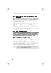
...To install the drivers to your system, please insert the support CD to your chassis. Please refer to the warning on this motherboard for the possible overclocking risk before you enable Untied Overclocking function, please enter "Overclock Mode" option of your system can work ...properly. 2 . 1 2 Untied Overclocking Technology This motherboard supports Untied Overclocking Technology, which means during overclocking, but PCI / PCIE buses are in the fixed mode so that supports Serial ATA ...
...To install the drivers to your system, please insert the support CD to your chassis. Please refer to the warning on this motherboard for the possible overclocking risk before you enable Untied Overclocking function, please enter "Overclock Mode" option of your system can work ...properly. 2 . 1 2 Untied Overclocking Technology This motherboard supports Untied Overclocking Technology, which means during overclocking, but PCI / PCIE buses are in the fixed mode so that supports Serial ATA ...
User Manual
Page 27
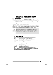
... features Boot To set up the computer. The BIOS FWH chip on the menu bar, and then press to choose among the selections on the motherboard stores the BIOS SETUP UTILITY. You may run the BIOS SETUP UTILITY when you start up the chipset features Exit To exit the current screen...
... features Boot To set up the computer. The BIOS FWH chip on the menu bar, and then press to choose among the selections on the motherboard stores the BIOS SETUP UTILITY. You may run the BIOS SETUP UTILITY when you start up the chipset features Exit To exit the current screen...
User Manual
Page 32
... the feature of the system caches. Ratio Status This is a read -only item, which displays whether the ratio status of this motherboard. If it requires a computer system with "No Execute (NX) Memory Protection" can utilize the additional hardware capabilities provided by Vanderpool Technology... This option will be hidden if the current CPU does not support No-Excute Memory Protection. Hyper Threading Technology To enable this motherboard is supported through the native processor instructions HLT and MWAIT and requires no hardware support from being used by malicious software to [...
... the feature of the system caches. Ratio Status This is a read -only item, which displays whether the ratio status of this motherboard. If it requires a computer system with "No Execute (NX) Memory Protection" can utilize the additional hardware capabilities provided by Vanderpool Technology... This option will be hidden if the current CPU does not support No-Excute Memory Protection. Hyper Threading Technology To enable this motherboard is supported through the native processor instructions HLT and MWAIT and requires no hardware support from being used by malicious software to [...


