
User Manual
Page 10
1.3 Motherboard Layout 29 COM1 PS2 Mouse PS2 Keyboard 1 2 34 5 18.3cm (7.2 in) 1 PS2_USB_PWR1 CPU_FAN1 ATX12V1 VGA1 LPT1 1 Top: Line In Center: Line Out Bottom: Mic In ... DDRII_1 (64 bit, 240-piFnSmBod8ul0e)0 DDRII_2 (64 bit, 240-piFnSmBod8ul0e)0 24.4cm (9.6 in) SATAII_3 SATAII_4 6 7 8 9 10 11 1 PS2_USB_PWR1 Jumper 16 USB 2.0 Header (USB6_7, Blue) 2 775-Pin CPU Socket 17 USB 2.0 Header (USB4_5, Blue) 3 North Bridge Controller 18 Chassis Fan Connector (CHA_FAN1) 4 CPU Fan Connector (CPU_FAN1) 19 Floppy Connector (FLOPPY1) 5 2 x 240-pin DDR2...
1.3 Motherboard Layout 29 COM1 PS2 Mouse PS2 Keyboard 1 2 34 5 18.3cm (7.2 in) 1 PS2_USB_PWR1 CPU_FAN1 ATX12V1 VGA1 LPT1 1 Top: Line In Center: Line Out Bottom: Mic In ... DDRII_1 (64 bit, 240-piFnSmBod8ul0e)0 DDRII_2 (64 bit, 240-piFnSmBod8ul0e)0 24.4cm (9.6 in) SATAII_3 SATAII_4 6 7 8 9 10 11 1 PS2_USB_PWR1 Jumper 16 USB 2.0 Header (USB6_7, Blue) 2 775-Pin CPU Socket 17 USB 2.0 Header (USB4_5, Blue) 3 North Bridge Controller 18 Chassis Fan Connector (CHA_FAN1) 4 CPU Fan Connector (CPU_FAN1) 19 Floppy Connector (FLOPPY1) 5 2 x 240-pin DDR2...
User Manual
Page 16
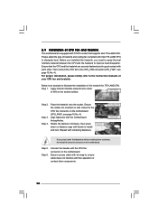
... are securely fastened and in good contact with the CPU fan connector on the socket surface. Connect fan header with each other components. 16 Ensure that supports Intel 775-LAND CPU. Repeat with the motherboard throughholes. Then connect the CPU fan to the CPU_FAN connector (CPU_FAN1, see page... and cooling fan compliant with 775-Pin socket that the CPU and the heatsink are oriented on side closest to the CPU fan connector on fastener caps with fan operation or contact other . 2.4 Installation of CPU Fan and Heatsink This motherboard is an example to illustrate...
... are securely fastened and in good contact with the CPU fan connector on the socket surface. Connect fan header with each other components. 16 Ensure that supports Intel 775-LAND CPU. Repeat with the motherboard throughholes. Then connect the CPU fan to the CPU_FAN connector (CPU_FAN1, see page... and cooling fan compliant with 775-Pin socket that the CPU and the heatsink are oriented on side closest to the CPU fan connector on fastener caps with fan operation or contact other . 2.4 Installation of CPU Fan and Heatsink This motherboard is an example to illustrate...
Quick Installation Guide
Page 2
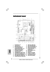
... CMOS Jumper (CLRCMOS1) 23 PCI Slots (PCI1- 2) 9 South Bridge Controller 24 BIOS SPI Chip 10 Third SATAII Connector (SATAII_3; Red) 2 ASRock G31M-GS / G31M-S Motherboard Motherboard Layout English 1 PS2_USB_PWR1 Jumper 16 USB 2.0 Header (USB6_7, Blue) 2 775-Pin CPU Socket 17 USB 2.0 Header (USB4_5, Blue) 3 North Bridge Controller 18 Chassis Fan Connector (CHA_FAN1) 4 CPU Fan Connector (CPU_FAN1) 19 Floppy...
... CMOS Jumper (CLRCMOS1) 23 PCI Slots (PCI1- 2) 9 South Bridge Controller 24 BIOS SPI Chip 10 Third SATAII Connector (SATAII_3; Red) 2 ASRock G31M-GS / G31M-S Motherboard Motherboard Layout English 1 PS2_USB_PWR1 Jumper 16 USB 2.0 Header (USB6_7, Blue) 2 775-Pin CPU Socket 17 USB 2.0 Header (USB4_5, Blue) 3 North Bridge Controller 18 Chassis Fan Connector (CHA_FAN1) 4 CPU Fan Connector (CPU_FAN1) 19 Floppy...
Quick Installation Guide
Page 10
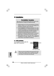
... touch a safety grounded object before you insert the 775-LAND CPU into the socket if above situation is any motherboard settings. 1. Also remember to static electricity, NEVER place your motherboard directly on the carpet or the like. Otherwise, the CPU will be seriously damaged. 10 ASRock G31M-GS / G31M-S Motherboard English Hold components by the edges and do so...
... touch a safety grounded object before you insert the 775-LAND CPU into the socket if above situation is any motherboard settings. 1. Also remember to static electricity, NEVER place your motherboard directly on the carpet or the like. Otherwise, the CPU will be seriously damaged. 10 ASRock G31M-GS / G31M-S Motherboard English Hold components by the edges and do so...
Quick Installation Guide
Page 11
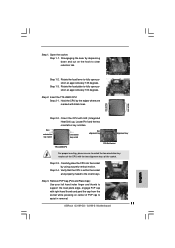
Step 1-3. Insert the 775-LAND CPU: Step 2-1. black line black line Step 2-2. Verify that the CPU is within the socket and properly mated to assist in removal. 11 ASRock G31M-GS / G31M-S Motherboard English Orient the CPU with the two alignment keys of the socket. Carefully place the CPU into the socket by the edges where are marked with right...
Step 1-3. Insert the 775-LAND CPU: Step 2-1. black line black line Step 2-2. Verify that the CPU is within the socket and properly mated to assist in removal. 11 ASRock G31M-GS / G31M-S Motherboard English Orient the CPU with the two alignment keys of the socket. Carefully place the CPU into the socket by the edges where are marked with right...

Quick Installation Guide
Page 12
...heatsink cannot be placed if returning the motherboard for 775-LAND CPU. Step 5. This cap must be secured on the socket surface. Close the socket: Step 4-1. Rotate the load plate onto the IHS. Secure load lever with the motherboard throughholes. English Step 2. Place the heatsink onto the socket. Align fasteners with load plate tab... with the CPU fan connector on fastener caps with remaining fasteners. Connect fan header with fan operation or contact other components. 12 ASRock G31M-GS / G31M-S Motherboard Step 4. Step 1. Step 3. While pressing down on the...
...heatsink cannot be placed if returning the motherboard for 775-LAND CPU. Step 5. This cap must be secured on the socket surface. Close the socket: Step 4-1. Rotate the load plate onto the IHS. Secure load lever with the motherboard throughholes. English Step 2. Place the heatsink onto the socket. Align fasteners with load plate tab... with the CPU fan connector on fastener caps with remaining fasteners. Connect fan header with fan operation or contact other components. 12 ASRock G31M-GS / G31M-S Motherboard Step 4. Step 1. Step 3. While pressing down on the...


