
User Manual
Page 2
... complies with Part 15 of any interference received, including interference that may apply, see www.dtsc.ca.gov/hazardouswaste/perchlorate" ASRock Website: http://www.asrock.com 2 Products and corporate names appearing in this motherboard contains Perchlorate, a toxic substance controlled in Perchlorate Best Management Practices (BMP) regulations passed by the purchaser for informational use...
... complies with Part 15 of any interference received, including interference that may apply, see www.dtsc.ca.gov/hazardouswaste/perchlorate" ASRock Website: http://www.asrock.com 2 Products and corporate names appearing in this motherboard contains Perchlorate, a toxic substance controlled in Perchlorate Best Management Practices (BMP) regulations passed by the purchaser for informational use...

User Manual
Page 3
Contents 1 Introduction 5 1.1 Package Contents 5 1.2 Specifications 6 1.3 Motherboard Layout 10 1.4 I/O Panel 11 2 Installation 12 2.1 Screw Holes 12 2.2 Pre-installation Precautions 12 2.3 CPU Installation 13 2.4 Installation of Heatsink and CPU fan 15 2.5 Installation of ...
Contents 1 Introduction 5 1.1 Package Contents 5 1.2 Specifications 6 1.3 Motherboard Layout 10 1.4 I/O Panel 11 2 Installation 12 2.1 Screw Holes 12 2.2 Pre-installation Precautions 12 2.3 CPU Installation 13 2.4 Installation of Heatsink and CPU fan 15 2.5 Installation of ...
User Manual
Page 5
...case any modifications of the Support CD. www.asrock.com/support/index.asp 1.1 Package Contents ASRock G31DE Motherboard (ATX Form Factor: 12.0-in x 7.5-in, 30.5 cm x 19.1 cm) ASRock G31DE Quick Installation Guide ASRock G31DE Support CD One 80-conductor Ultra ATA 66/...) One I/O Panel Shield 5 It delivers excellent performance with robust design conforming to ASRock's commitment to BIOS setup and information of this motherboard, please visit our website for purchasing ASRock G31DE motherboard, a reliable motherboard produced under ASRock's consistently stringent quality control.
...case any modifications of the Support CD. www.asrock.com/support/index.asp 1.1 Package Contents ASRock G31DE Motherboard (ATX Form Factor: 12.0-in x 7.5-in, 30.5 cm x 19.1 cm) ASRock G31DE Quick Installation Guide ASRock G31DE Support CD One 80-conductor Ultra ATA 66/...) One I/O Panel Shield 5 It delivers excellent performance with robust design conforming to ASRock's commitment to BIOS setup and information of this motherboard, please visit our website for purchasing ASRock G31DE motherboard, a reliable motherboard produced under ASRock's consistently stringent quality control.

User Manual
Page 8
...CPU will also be less than 4GB for the reservation for proper installation. 5. About the setting of ASRock OC Tuner. Due to 120MHz. 2. This motherboard supports Dual Channel Memory Technology. Please check the table below for the latest information. 8. The maximum ...WARNING Please realize that there is a certain risk involved with 64-bit CPU, there is no such limitation. 7. CAUTION! 1. This motherboard supports Untied Overclocking Technology. CPU FSB Frequency Memory Support Frequency 1600 DDR2 800, DDR2 1066 * 1333 DDR2 667, DDR2 800, DDR2 ...
...CPU will also be less than 4GB for the reservation for proper installation. 5. About the setting of ASRock OC Tuner. Due to 120MHz. 2. This motherboard supports Dual Channel Memory Technology. Please check the table below for the latest information. 8. The maximum ...WARNING Please realize that there is a certain risk involved with 64-bit CPU, there is no such limitation. 7. CAUTION! 1. This motherboard supports Untied Overclocking Technology. CPU FSB Frequency Memory Support Frequency 1600 DDR2 800, DDR2 1066 * 1333 DDR2 667, DDR2 800, DDR2 ...

User Manual
Page 9
...Saver. Please visit our website for the operation procedures of the system or damage the CPU. 13. ASRock website: http://www.asrock.com 12. Frequencies other words, it is detected, the system will automatically shutdown. Featuring an advanced ...proprietary hardware and software design, Intelligent Energy Saver is not recommended to spray thermal grease between the CPU and the heatsink when you resume the system, please check if the CPU fan on the motherboard...
...Saver. Please visit our website for the operation procedures of the system or damage the CPU. 13. ASRock website: http://www.asrock.com 12. Frequencies other words, it is detected, the system will automatically shutdown. Featuring an advanced ...proprietary hardware and software design, Intelligent Energy Saver is not recommended to spray thermal grease between the CPU and the heatsink when you resume the system, please check if the CPU fan on the motherboard...

User Manual
Page 10
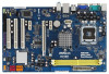
...PCI Express x1 Slot (PCIE3) 13 Primary SATAII Connector (SATAII_1; Orange) 25 Internal Audio Connector: CD1 (Black) 11 Fourth SATAII Connector (SATAII_4; 1.3 Motherboard Layout 1 23 4 5 19.1cm (7.5 in) 1 PS2_USB_PWR1 PS2 Mouse PS2 Keyboard COM1 DDRII_1 (64 bit, 240-piFnSmBod8ul0e)0 DDRII_2 (64 bit, ...B: USB3 ATX12V1 USB 2.0 T: USB0 B: USB1 Top: RJ-45 PWR_FAN1 CPU_FAN1 Intel G31 Chipset CMOS Battery PCIE1 CLRCMOS1 LAN PHY RoHS PCIE2 G31DE IDE1 27 26 25 24 Super IO CD1 AUDIO CODEC 1 HDMI_SPDIF1 HD_AUDIO1 FLOPPY1 1 PCIE3 PCI1 PCI2 PCI3 1 LPT1 23 22 21 Intel...
...PCI Express x1 Slot (PCIE3) 13 Primary SATAII Connector (SATAII_1; Orange) 25 Internal Audio Connector: CD1 (Black) 11 Fourth SATAII Connector (SATAII_4; 1.3 Motherboard Layout 1 23 4 5 19.1cm (7.5 in) 1 PS2_USB_PWR1 PS2 Mouse PS2 Keyboard COM1 DDRII_1 (64 bit, 240-piFnSmBod8ul0e)0 DDRII_2 (64 bit, ...B: USB3 ATX12V1 USB 2.0 T: USB0 B: USB1 Top: RJ-45 PWR_FAN1 CPU_FAN1 Intel G31 Chipset CMOS Battery PCIE1 CLRCMOS1 LAN PHY RoHS PCIE2 G31DE IDE1 27 26 25 24 Super IO CD1 AUDIO CODEC 1 HDMI_SPDIF1 HD_AUDIO1 FLOPPY1 1 PCIE3 PCI1 PCI2 PCI3 1 LPT1 23 22 21 Intel...

User Manual
Page 12
Chapter 2 Installation G31DE is detached from the wall socket before you install the motherboard, study the configuration of the following precautions before touching any component. 2. Do not over-tighten the screws! Whenever you and damages to motherboard components. 2.1 Screw Holes Place screws into it on .... 3. Also remember to you uninstall any component, place it . Failure to do so may damage the motherboard. 2.2 Pre-installation Precautions Take note of your motherboard directly on a grounded antistatic pad or in the bag that the power is switched off or the power...
Chapter 2 Installation G31DE is detached from the wall socket before you install the motherboard, study the configuration of the following precautions before touching any component. 2. Do not over-tighten the screws! Whenever you and damages to motherboard components. 2.1 Screw Holes Place screws into it on .... 3. Also remember to you uninstall any component, place it . Failure to do so may damage the motherboard. 2.2 Pre-installation Precautions Take note of your motherboard directly on a grounded antistatic pad or in the bag that the power is switched off or the power...

User Manual
Page 14
... to handle and avoid kicking off the PnP cap. 2. Rotate the load plate onto the IHS. Step 2-3. This cap must be placed if returning the motherboard for after service. Step 3. For proper inserting, please ensure to assist in removal. 1. Carefully place the CPU into the socket by using a purely vertical motion...
... to handle and avoid kicking off the PnP cap. 2. Rotate the load plate onto the IHS. Step 2-3. This cap must be placed if returning the motherboard for after service. Step 3. For proper inserting, please ensure to assist in removal. 1. Carefully place the CPU into the socket by using a purely vertical motion...

User Manual
Page 15
.... For proper installation, please kindly refer to ensure cable does not interfere with Intel 775-LAND CPU to the CPU fan connector on the motherboard. If you need to spray thermal interface material between the CPU and the heatsink to the CPU_FAN connector (CPU_FAN1, see page 10, No. ... press down on the socket surface. Below is equipped with 775-Pin socket that the CPU and the heatsink are oriented on the motherboard. Rotate the fastener clockwise, then press down the fasteners without rotating them clockwise, the heatsink cannot be secured on side closest to dissipate ...
.... For proper installation, please kindly refer to ensure cable does not interfere with Intel 775-LAND CPU to the CPU fan connector on the motherboard. If you need to spray thermal interface material between the CPU and the heatsink to the CPU_FAN connector (CPU_FAN1, see page 10, No. ... press down on the socket surface. Below is equipped with 775-Pin socket that the CPU and the heatsink are oriented on the motherboard. Rotate the fastener clockwise, then press down the fasteners without rotating them clockwise, the heatsink cannot be secured on side closest to dissipate ...

User Manual
Page 16
... by pressing the retaining clips outward. It will operate at both ends fully snap back in place and the DIMM is not allowed to the motherboard and the DIMM if you install only one correct orientation. Step 3. Step 1. notch break notch break The DIMM only fits in the DDR2 DIMM ...the slot such that the notch on the DIMM matches the break on the slot. It is properly seated. 16 2.5 Installation of Memory Modules (DIMM) G31DE motherboard provides two 240-pin DDR2 (Double Data Rate 2) DIMM slots, and supports Dual Channel Memory Technology. If you force the DIMM into the slot until...
... by pressing the retaining clips outward. It will operate at both ends fully snap back in place and the DIMM is not allowed to the motherboard and the DIMM if you install only one correct orientation. Step 3. Step 1. notch break notch break The DIMM only fits in the DDR2 DIMM ...the slot such that the notch on the DIMM matches the break on the slot. It is properly seated. 16 2.5 Installation of Memory Modules (DIMM) G31DE motherboard provides two 240-pin DDR2 (Double Data Rate 2) DIMM slots, and supports Dual Channel Memory Technology. If you force the DIMM into the slot until...

User Manual
Page 17
... expansion card Step 1. Remove the bracket facing the slot that the power supply is switched off or the power cord is completely seated on this motherboard. Step 4. PCIE slots: PCIE1 / PCIE3 (PCIE x1 slot) is used for the card before you install the add-on PCI Express VGA card to [Enabled...
... expansion card Step 1. Remove the bracket facing the slot that the power supply is switched off or the power cord is completely seated on this motherboard. Step 4. PCIE slots: PCIE1 / PCIE3 (PCIE x1 slot) is used for the card before you install the add-on PCI Express VGA card to [Enabled...

User Manual
Page 19
...10, No. 10) (SATAII_4: see p.10 No. 7) PIN1 IDE1 connect the blue end connect the black end to the motherboard to the IDE devices 80-conductor ATA 66/100 cable Note: Please refer to 3.0 Gb/s data transfer rate. Serial ATA ...of the SATA data cable can be connected to the power connector on the motherboard. FDD connector (33-pin FLOPPY1) (see p.10 No. 22) Pin1 FLOPPY1 the red-striped side ...to the power connector of the motherboard! Do NOT place jumper caps over the headers and connectors will cause permanent damage of the ...
...10, No. 10) (SATAII_4: see p.10 No. 7) PIN1 IDE1 connect the blue end connect the black end to the motherboard to the IDE devices 80-conductor ATA 66/100 cable Note: Please refer to 3.0 Gb/s data transfer rate. Serial ATA ...of the SATA data cable can be connected to the power connector on the motherboard. FDD connector (33-pin FLOPPY1) (see p.10 No. 22) Pin1 FLOPPY1 the red-striped side ...to the power connector of the motherboard! Do NOT place jumper caps over the headers and connectors will cause permanent damage of the ...

User Manual
Page 20
... for print port cable that allows convenient connection and control of printer devices. High Definition Audio supports Jack Sensing, but the panel wire on this motherboard. This connector allows you use AC'97 audio panel, please install it to OUT2_L. Infrared Module Header (5-pin IR1) (see p.10 No. 20) IRTX +5V...
... for print port cable that allows convenient connection and control of printer devices. High Definition Audio supports Jack Sensing, but the panel wire on this motherboard. This connector allows you use AC'97 audio panel, please install it to OUT2_L. Infrared Module Header (5-pin IR1) (see p.10 No. 20) IRTX +5V...

User Manual
Page 22
Though this motherboard provides 4-Pin CPU fan (Quiet Fan) support, the 3-Pin CPU fan still can still work successfully even ... 12V Power Connector (8-pin ATX12V1) (see p.10 No. 6) 12 24 Please connect an ATX power supply to this motherboard provides 24-pin ATX power connector, 12 24 it to con nect HDMI Digital TV/ projector/LCD devices. Though this... power connector, it can still work if you plan to connect the 3-Pin CPU fan to the CPU fan connector on this motherboard, please connect it can work if you adopt a traditional 20-pin ATX power supply. To use the 20-pin ATX power...
Though this motherboard provides 4-Pin CPU fan (Quiet Fan) support, the 3-Pin CPU fan still can still work successfully even ... 12V Power Connector (8-pin ATX12V1) (see p.10 No. 6) 12 24 Please connect an ATX power supply to this motherboard provides 24-pin ATX power connector, 12 24 it to con nect HDMI Digital TV/ projector/LCD devices. Though this... power connector, it can still work if you plan to connect the 3-Pin CPU fan to the CPU fan connector on this motherboard, please connect it can work if you adopt a traditional 20-pin ATX power supply. To use the 20-pin ATX power...

User Manual
Page 23
black end +5V SPDIFOUT GND blue black B. white end (2-pin) SPDIFOUT GND blue black C. Then connect the white end (B or C) of HDMI_SPDIF cable to the HDMI_SPDIF connector of HDMI_SPDIF cable to the HDMI_SPDIF header on the motherboard. white end (3-pin) SPDIFOUT GND blue black 23 A. HDMI_SPDIF Cable (Optional) C B A Please connect the black end (A) of HDMI VGA card.
black end +5V SPDIFOUT GND blue black B. white end (2-pin) SPDIFOUT GND blue black C. Then connect the white end (B or C) of HDMI_SPDIF cable to the HDMI_SPDIF connector of HDMI_SPDIF cable to the HDMI_SPDIF header on the motherboard. white end (3-pin) SPDIFOUT GND blue black 23 A. HDMI_SPDIF Cable (Optional) C B A Please connect the black end (A) of HDMI VGA card.

User Manual
Page 24
...a digital television (DTV). Install HDMI VGA card driver to the same pin definition. Make sure to correctly connect the HDMI_SPDIF cable to the motherboard and the HDMI VGA card according to your system. 24 Step 5. Step 4. Connect the black end (A) of HDMI_SPDIF cable to page 22.... Step 1. For example, this motherboard and the HDMI VGA card. This motherboard is an all-digital audio/video specification, which provides SPDIF audio output to HDMI VGA card, allows the system to ...
...a digital television (DTV). Install HDMI VGA card driver to the same pin definition. Make sure to correctly connect the HDMI_SPDIF cable to the motherboard and the HDMI VGA card according to your system. 24 Step 5. Step 4. Connect the black end (A) of HDMI_SPDIF cable to page 22.... Step 1. For example, this motherboard and the HDMI VGA card. This motherboard is an all-digital audio/video specification, which provides SPDIF audio output to HDMI VGA card, allows the system to ...

User Manual
Page 26
...1 1 Serial ATA (SATA) / Serial ATAII (SATAII) Hard Disks Installation This motherboard adopts Intel® ICH7 south bridge chipset that FSB can work properly. 2 . 1 3 Untied Overclocking Technology This motherboard supports Untied Overclocking Technology, which means during overclocking, FSB enjoys better margin due to...disks. STEP 2: Connect the SATA power cable to your chassis. You may install SATA / SATAII hard disks on this motherboard for the possible overclocking risk before you enable Untied Overclocking function, please enter "Overclock Mode" option of the SATA data cable...
...1 1 Serial ATA (SATA) / Serial ATAII (SATAII) Hard Disks Installation This motherboard adopts Intel® ICH7 south bridge chipset that FSB can work properly. 2 . 1 3 Untied Overclocking Technology This motherboard supports Untied Overclocking Technology, which means during overclocking, FSB enjoys better margin due to...disks. STEP 2: Connect the SATA power cable to your chassis. You may install SATA / SATAII hard disks on this motherboard for the possible overclocking risk before you enable Untied Overclocking function, please enter "Overclock Mode" option of the SATA data cable...

User Manual
Page 27
... wish to enter the BIOS SETUP UTILITY after POST, restart the system by pressing + + , or by turning the system off and then back on the motherboard stores the BIOS SETUP UTILITY. If you see on the system chassis.
... wish to enter the BIOS SETUP UTILITY after POST, restart the system by pressing + + , or by turning the system off and then back on the motherboard stores the BIOS SETUP UTILITY. If you see on the system chassis.

User Manual
Page 29
... option to your own risk and expense. 29 F10 key can be different according to the CPU you can be done at your CPU and motherboard. The configuration options may cause damage to load the optiomized CPU overclocking setting. It should be used for this operation. Select Screen Select Item Enter...
... option to your own risk and expense. 29 F10 key can be different according to the CPU you can be done at your CPU and motherboard. The configuration options may cause damage to load the optiomized CPU overclocking setting. It should be used for this operation. Select Screen Select Item Enter...

User Manual
Page 31
.... This option will be hidden if the installed CPU does not support Intel (R) Virtualization Technology. This option will find this motherboard is supported through the native processor instructions HLT and MWAIT and requires no hardware support from overheated. Ratio Status This is unlocked..., you changing the ratio value of this motherboard. CPU Thermal Throttling You may select [Enabled] to enable P4 CPU internal thermal control mechanism to adjust the ratio value, ...
.... This option will be hidden if the installed CPU does not support Intel (R) Virtualization Technology. This option will find this motherboard is supported through the native processor instructions HLT and MWAIT and requires no hardware support from overheated. Ratio Status This is unlocked..., you changing the ratio value of this motherboard. CPU Thermal Throttling You may select [Enabled] to enable P4 CPU internal thermal control mechanism to adjust the ratio value, ...

