
User Manual
Page 6
... slots - 3 x PCI slots - Southbridge: Intel® ICH7 - shared memory 384MB (see CAUTION 5) - Supports Wake-On-LAN I /O - PCIE x1 Gigabit LAN 10/100/1000 Mb/s - LGA 775 for Intel® CoreTM 2 Extreme / CoreTM 2 Quad / CoreTM 2 Duo / Pentium® Dual Core / Celeron® Dual Core / Celeron®, supporting Penryn Quad Core Yorkfield and...
... slots - 3 x PCI slots - Southbridge: Intel® ICH7 - shared memory 384MB (see CAUTION 5) - Supports Wake-On-LAN I /O - PCIE x1 Gigabit LAN 10/100/1000 Mb/s - LGA 775 for Intel® CoreTM 2 Extreme / CoreTM 2 Quad / CoreTM 2 Duo / Pentium® Dual Core / Celeron® Dual Core / Celeron®, supporting Penryn Quad Core Yorkfield and...

User Manual
Page 10
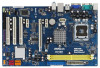
... B: USB3 ATX12V1 USB 2.0 T: USB0 B: USB1 Top: RJ-45 PWR_FAN1 CPU_FAN1 Intel G31 Chipset CMOS Battery PCIE1 CLRCMOS1 LAN PHY RoHS PCIE2 G31DE IDE1 27 26 25 24 Super IO CD1 AUDIO CODEC 1 HDMI_SPDIF1 HD_AUDIO1 FLOPPY1 1 PCIE3 PCI1 PCI2 PCI3 1 LPT1 23 22 21 Intel ICH7... 7 8 9 10 11 12 13 1 PS2_USB_PWR1 Jumper 17 Chassis Fan Connector (CHA_FAN1) 2 ATX 12V Connector (ATX12V1) 18 USB 2.0 Header (USB6_7, Blue) 3 775-Pin CPU Socket 19 USB 2.0 Header (USB4_5, Blue) 4 North Bridge Controller 20 Infrared Module Header (IR1) 5 2 x 240-pin DDR2 DIMM Slots 21 Print Port...
... B: USB3 ATX12V1 USB 2.0 T: USB0 B: USB1 Top: RJ-45 PWR_FAN1 CPU_FAN1 Intel G31 Chipset CMOS Battery PCIE1 CLRCMOS1 LAN PHY RoHS PCIE2 G31DE IDE1 27 26 25 24 Super IO CD1 AUDIO CODEC 1 HDMI_SPDIF1 HD_AUDIO1 FLOPPY1 1 PCIE3 PCI1 PCI2 PCI3 1 LPT1 23 22 21 Intel ICH7... 7 8 9 10 11 12 13 1 PS2_USB_PWR1 Jumper 17 Chassis Fan Connector (CHA_FAN1) 2 ATX 12V Connector (ATX12V1) 18 USB 2.0 Header (USB6_7, Blue) 3 775-Pin CPU Socket 19 USB 2.0 Header (USB4_5, Blue) 4 North Bridge Controller 20 Infrared Module Header (IR1) 5 2 x 240-pin DDR2 DIMM Slots 21 Print Port...

User Manual
Page 13
...depressing down and out on the socket. Step 1-2. Step 1-3. Locate Pin1 and the two orientation key notches. Insert the 775-LAND CPU: Step 2-1. Rotate the load lever to fully open position at approximately 100 degrees. 2.3 CPU Installation For the installation of Intel... 775-LAND CPU, please follow the steps below. 775-Pin Socket Overview Before you insert the 775-LAND CPU into the socket if above situation is any bent pin on the ShoockoetkMatrokedcCleoranerr retention...
...depressing down and out on the socket. Step 1-2. Step 1-3. Locate Pin1 and the two orientation key notches. Insert the 775-LAND CPU: Step 2-1. Rotate the load lever to fully open position at approximately 100 degrees. 2.3 CPU Installation For the installation of Intel... 775-LAND CPU, please follow the steps below. 775-Pin Socket Overview Before you insert the 775-LAND CPU into the socket if above situation is any bent pin on the ShoockoetkMatrokedcCleoranerr retention...

User Manual
Page 15
... fan connector on the motherboard. Repeat with the motherboard throughholes. Connect fan header with Intel 775-LAND CPU to improve heat dissipation. Please adopt the type of the heatsink for 775-LAND CPU. For proper installation, please kindly refer to the instruction manuals of CPU Fan... No. 31). If you need to spray thermal interface material between the CPU and the heatsink to dissipate heat. Ensure that supports Intel 775-LAND CPU. Align fasteners with remaining fasteners. 2.4 Installation of your CPU fan and heatsink. Step 6. Then connect the CPU fan to ...
... fan connector on the motherboard. Repeat with the motherboard throughholes. Connect fan header with Intel 775-LAND CPU to improve heat dissipation. Please adopt the type of the heatsink for 775-LAND CPU. For proper installation, please kindly refer to the instruction manuals of CPU Fan... No. 31). If you need to spray thermal interface material between the CPU and the heatsink to dissipate heat. Ensure that supports Intel 775-LAND CPU. Align fasteners with remaining fasteners. 2.4 Installation of your CPU fan and heatsink. Step 6. Then connect the CPU fan to ...

Quick Installation Guide
Page 2
...Purple) 30 Power Fan Connector (PWR_FAN1) 15 System Panel Header (PANEL1, Orange) 31 CPU Fan Connector (CPU_FAN1) 16 BIOS SPI Chip 2 ASRock G31DE Motherboard Yellow) 22 Floppy Connector (FLOPPY1) 6 ATX Power Connector (ATXPWR1) 23 Front Panel Audio Header 7 IDE1 Connector (IDE1, Blue) (... Motherboard Layout English 1 PS2_USB_PWR1 Jumper 17 Chassis Fan Connector (CHA_FAN1) 2 ATX 12V Connector (ATX12V1) 18 USB 2.0 Header (USB6_7, Blue) 3 775-Pin CPU Socket 19 USB 2.0 Header (USB4_5, Blue) 4 North Bridge Controller 20 Infrared Module Header (IR1) 5 2 x 240-pin DDR2 ...
...Purple) 30 Power Fan Connector (PWR_FAN1) 15 System Panel Header (PANEL1, Orange) 31 CPU Fan Connector (CPU_FAN1) 16 BIOS SPI Chip 2 ASRock G31DE Motherboard Yellow) 22 Floppy Connector (FLOPPY1) 6 ATX Power Connector (ATXPWR1) 23 Front Panel Audio Header 7 IDE1 Connector (IDE1, Blue) (... Motherboard Layout English 1 PS2_USB_PWR1 Jumper 17 Chassis Fan Connector (CHA_FAN1) 2 ATX 12V Connector (ATX12V1) 18 USB 2.0 Header (USB6_7, Blue) 3 775-Pin CPU Socket 19 USB 2.0 Header (USB4_5, Blue) 4 North Bridge Controller 20 Infrared Module Header (IR1) 5 2 x 240-pin DDR2 ...

Quick Installation Guide
Page 5
...- 1 x VGA Port - 4 x Ready-to-Use USB 2.0 Ports - 1 x RJ-45 LAN Port with all FSB1600/1333/1066/800MHz CPUs (see CAUTION 1) - LGA 775 for Intel® CoreTM 2 Extreme / CoreTM 2 Quad / CoreTM 2 Duo / Pentium® Dual Core / Celeron® Dual Core / Celeron®, supporting Penryn Quad Core ...800/667 non-ECC, un-buffered memory (see CAUTION 2) - ATX Form Factor: 12.0-in x 7.5-in / Front Speaker / Microphone English 5 ASRock G31DE Motherboard Max. Supports EM64T CPU - Pixel Shader 2.0, DirectX 9.0 - PCIE x1 Gigabit LAN 10/100/1000 Mb/s - Supports Wake-On-LAN I /O -
...- 1 x VGA Port - 4 x Ready-to-Use USB 2.0 Ports - 1 x RJ-45 LAN Port with all FSB1600/1333/1066/800MHz CPUs (see CAUTION 1) - LGA 775 for Intel® CoreTM 2 Extreme / CoreTM 2 Quad / CoreTM 2 Duo / Pentium® Dual Core / Celeron® Dual Core / Celeron®, supporting Penryn Quad Core ...800/667 non-ECC, un-buffered memory (see CAUTION 2) - ATX Form Factor: 12.0-in x 7.5-in / Front Speaker / Microphone English 5 ASRock G31DE Motherboard Max. Supports EM64T CPU - Pixel Shader 2.0, DirectX 9.0 - PCIE x1 Gigabit LAN 10/100/1000 Mb/s - Supports Wake-On-LAN I /O -

Quick Installation Guide
Page 9
Installation Pre-installation Precautions Take note of Intel 775-LAND CPU, please follow the steps below. 775-Pin Socket Overview Before you install motherboard components or change any component. To avoid damaging the motherboard components due to the chassis, please do not ... insert the 775-LAND CPU into the socket if above situation is any component, place it on the carpet or the like. 2. Failure to insert the CPU into the socket, please check if the CPU surface is unclean or if there is found. Otherwise, the CPU will be seriously damaged. 9 ASRock G31DE Motherboard...
Installation Pre-installation Precautions Take note of Intel 775-LAND CPU, please follow the steps below. 775-Pin Socket Overview Before you install motherboard components or change any component. To avoid damaging the motherboard components due to the chassis, please do not ... insert the 775-LAND CPU into the socket if above situation is any component, place it on the carpet or the like. 2. Failure to insert the CPU into the socket, please check if the CPU surface is unclean or if there is found. Otherwise, the CPU will be seriously damaged. 9 ASRock G31DE Motherboard...

Quick Installation Guide
Page 10
Step 1. Open the socket: Step 1-1. Step 1-2. Pin1 orientation key notch orientation key notch Pin1 alignment key alignment key 775-LAND CPU 775-Pin Socket For proper inserting, please ensure to match the two orientation key notches of the CPU with right hand thumb ... Insert the 775-LAND CPU: Step 2-1. Orient the CPU with black lines. Rotate the load lever to fully open position at approximately 100 degrees. black line black line English Step 2-2. Verify that the CPU is within the socket and properly mated to assist in removal. 10 ASRock G31DE Motherboard Step ...
Step 1. Open the socket: Step 1-1. Step 1-2. Pin1 orientation key notch orientation key notch Pin1 alignment key alignment key 775-LAND CPU 775-Pin Socket For proper inserting, please ensure to match the two orientation key notches of the CPU with right hand thumb ... Insert the 775-LAND CPU: Step 2-1. Orient the CPU with black lines. Rotate the load lever to fully open position at approximately 100 degrees. black line black line English Step 2-2. Verify that the CPU is within the socket and properly mated to assist in removal. 10 ASRock G31DE Motherboard Step ...

Quick Installation Guide
Page 11
... avoid kicking off the PnP cap. 2. While pressing down the fasteners without rotating them clockwise, the heatsink cannot be placed if returning the motherboard for 775-LAND CPU. Secure load lever with the CPU fan connector on fastener caps with remaining fasteners. Below is recommended to use the cap tab to... not interfere with the motherboard throughholes. 1. This cap must be secured on the socket surface. Align fasteners with fan operation or contact other components. 11 ASRock G31DE Motherboard
... avoid kicking off the PnP cap. 2. While pressing down the fasteners without rotating them clockwise, the heatsink cannot be placed if returning the motherboard for 775-LAND CPU. Secure load lever with the CPU fan connector on fastener caps with remaining fasteners. Below is recommended to use the cap tab to... not interfere with the motherboard throughholes. 1. This cap must be secured on the socket surface. Align fasteners with fan operation or contact other components. 11 ASRock G31DE Motherboard