
User Manual
Page 7
... the motherboard and step-by-step installation guides. In this documentation will be available on ASRock's website as well. ASRock website http://www.asrock.com. 1.1 Package Contents • ASRock Fatal1ty Z97 Professional Series Motherboard (ATX Form Factor) • ASRock Fatal1ty Z97 Professional Series Quick Installation Guide • ASRock Fatal1ty Z97 Professional Series Support CD • 4 x Serial ATA (SATA) Data Cables (Optional) • 1 x I/O Panel Shield •...
... the motherboard and step-by-step installation guides. In this documentation will be available on ASRock's website as well. ASRock website http://www.asrock.com. 1.1 Package Contents • ASRock Fatal1ty Z97 Professional Series Motherboard (ATX Form Factor) • ASRock Fatal1ty Z97 Professional Series Quick Installation Guide • ASRock Fatal1ty Z97 Professional Series Support CD • 4 x Serial ATA (SATA) Data Cables (Optional) • 1 x I/O Panel Shield •...

User Manual
Page 8
... • 12 Power Phase design • Supports Intel® Turbo Boost 2.0 Technology • Supports Intel® K-Series unlocked CPUs • Supports ASRock BCLK Full-range Overclocking • Intel® Z97 Memory • Dual Channel DDR3 Memory Technology • 4 x DDR3 DIMM Slots • Supports DDR3 3200+(OC)/2933 (OC)/2800(OC)/2400(OC...
... • 12 Power Phase design • Supports Intel® Turbo Boost 2.0 Technology • Supports Intel® K-Series unlocked CPUs • Supports ASRock BCLK Full-range Overclocking • Intel® Z97 Memory • Dual Channel DDR3 Memory Technology • 4 x DDR3 DIMM Slots • Supports DDR3 3200+(OC)/2933 (OC)/2800(OC)/2400(OC...

User Manual
Page 9
...® Security Wake On Internet Technology (on Qualcomm® Atheros® KillerTM E2200 Series) • Supports Wake-On-LAN • Supports Lightning/ESD Protection (ASRock Full Spike Protection) • Supports Energy Efficient Ethernet 802.3az • Supports PXE 3 English resolution up to 4K x 2K (4096x2304) @ 24Hz •.... shared memory 1792MB • Dual graphics output: Support HDMI and DiaplayPort 1.2 ports by independent display controllers • Supports HDMI with max. Fatal1ty Z97 Professional Series Audio LAN • Pixel Shader 5.0, DirectX 11.1 • Max.
...® Security Wake On Internet Technology (on Qualcomm® Atheros® KillerTM E2200 Series) • Supports Wake-On-LAN • Supports Lightning/ESD Protection (ASRock Full Spike Protection) • Supports Energy Efficient Ethernet 802.3az • Supports PXE 3 English resolution up to 4K x 2K (4096x2304) @ 24Hz •.... shared memory 1792MB • Dual graphics output: Support HDMI and DiaplayPort 1.2 ports by independent display controllers • Supports HDMI with max. Fatal1ty Z97 Professional Series Audio LAN • Pixel Shader 5.0, DirectX 11.1 • Max.

User Manual
Page 10
...; 6 x SATA3 6.0 Gb/s Connectors by Intel® Z97, support RAID (RAID 0, RAID 1, RAID 5, RAID 10, Intel Rapid Storage Technology 13 and Intel Smart Response Technology), NCQ, AHCI, Hot Plug and ASRock HDD Saver Technology • 2 x SATA3 6.0 Gb/s ...• 1 x eSATA Connector • 3 x USB 2.0 Ports (Supports ESD Protection (ASRock Full Spike Protection)) • 1 x Fatal1ty Mouse Port (USB 2.0) (Supports ESD Protection (ASRock Full Spike Protection)) • 4 x USB 3.0 Ports (Supports ESD Protection (ASRock Full Spike Protection)) • 2 x RJ-45 LAN Ports with SATA3_1 and SATA3_2;
...; 6 x SATA3 6.0 Gb/s Connectors by Intel® Z97, support RAID (RAID 0, RAID 1, RAID 5, RAID 10, Intel Rapid Storage Technology 13 and Intel Smart Response Technology), NCQ, AHCI, Hot Plug and ASRock HDD Saver Technology • 2 x SATA3 6.0 Gb/s ...• 1 x eSATA Connector • 3 x USB 2.0 Ports (Supports ESD Protection (ASRock Full Spike Protection)) • 1 x Fatal1ty Mouse Port (USB 2.0) (Supports ESD Protection (ASRock Full Spike Protection)) • 4 x USB 3.0 Ports (Supports ESD Protection (ASRock Full Spike Protection)) • 2 x RJ-45 LAN Ports with SATA3_1 and SATA3_2;

User Manual
Page 11
Fatal1ty Z97 Professional Series BIOS Feature Hardware Monitor OS • 3 x Chassis Fan Connectors (1 x 4-pin, 2 x 3-pin) • 1 x Power Fan Connector (3-pin) • 1 x 24 pin ATX Power Connector &#... Audio Connector • 1 x Thunderbolt AIC Connector • 2 x USB 2.0 Headers (Support 4 USB 2.0 ports) (Supports ESD Protection (ASRock Full Spike Protection)) • 2 x USB 3.0 Headers (Support 4 USB 3.0 ports) (ASMedia ASM1074 hub) (Supports ESD Protection (ASRock Full Spike Protection)) • 1 x Dr. Debug with LED • 1 x Power Switch with LED • 1 x Reset Switch with...
Fatal1ty Z97 Professional Series BIOS Feature Hardware Monitor OS • 3 x Chassis Fan Connectors (1 x 4-pin, 2 x 3-pin) • 1 x Power Fan Connector (3-pin) • 1 x 24 pin ATX Power Connector &#... Audio Connector • 1 x Thunderbolt AIC Connector • 2 x USB 2.0 Headers (Support 4 USB 2.0 ports) (Supports ESD Protection (ASRock Full Spike Protection)) • 2 x USB 3.0 Headers (Support 4 USB 3.0 ports) (ASMedia ASM1074 hub) (Supports ESD Protection (ASRock Full Spike Protection)) • 1 x Dr. Debug with LED • 1 x Power Switch with LED • 1 x Reset Switch with...

User Manual
Page 13
1.3 Motherboard Layout 1 USB 2.0 T: USB0 B: USB1 PS2 Keyboard/ Mouse 37 Clr CMOS ATX12V1 Fatal1ty Z97 Professional Series 2 3 4 CPU_FAN1 CPU_FAN2 5 6 PWR_FAN1 DP_1 HDMI1 DDR3_A1 (64 bit, 240-pin module) DDR3_A2 (64 bit, 240-pin module) DDR3_B1 (64 bit, ...Central/Bass LINE IN Center: REAR SPK FRONT Bottom: Optical SPDIF Center: Bottom: MIC IN 34 Top: PCIE_PWR1 T B1 1 RoHS CHA_FAN2 PCIE1 Killer E2200 Z97 Professional PCIE2 1 FATAL TY M2_2 NUT5 NUT4 NUT3 NUT2 NUT1 SATA3_A1 1 USB3_4_5 1 USB3_6_7 7 8 9 1 SATA_PWR_1 10 11 SATA3_A2 12 13 14 SATA3_3 SATA3_0 15...
1.3 Motherboard Layout 1 USB 2.0 T: USB0 B: USB1 PS2 Keyboard/ Mouse 37 Clr CMOS ATX12V1 Fatal1ty Z97 Professional Series 2 3 4 CPU_FAN1 CPU_FAN2 5 6 PWR_FAN1 DP_1 HDMI1 DDR3_A1 (64 bit, 240-pin module) DDR3_A2 (64 bit, 240-pin module) DDR3_B1 (64 bit, ...Central/Bass LINE IN Center: REAR SPK FRONT Bottom: Optical SPDIF Center: Bottom: MIC IN 34 Top: PCIE_PWR1 T B1 1 RoHS CHA_FAN2 PCIE1 Killer E2200 Z97 Professional PCIE2 1 FATAL TY M2_2 NUT5 NUT4 NUT3 NUT2 NUT1 SATA3_A1 1 USB3_4_5 1 USB3_6_7 7 8 9 1 SATA_PWR_1 10 11 SATA3_A2 12 13 14 SATA3_3 SATA3_0 15...

User Manual
Page 15
No. Description 34 PCIe Power Connector (PCIE_PWR1) 35 Thunderbolt AIC Connector (TB1) 36 Chassis Fan Connector (CHA_FAN2) 37 Chassis Fan Connector (CHA_FAN3) Fatal1ty Z97 Professional Series English 9
No. Description 34 PCIe Power Connector (PCIE_PWR1) 35 Thunderbolt AIC Connector (TB1) 36 Chassis Fan Connector (CHA_FAN2) 37 Chassis Fan Connector (CHA_FAN3) Fatal1ty Z97 Professional Series English 9

User Manual
Page 17
... Off Orange Green Description 10Mbps connection 100Mbps connection 1Gbps connection ** If you need to connect a front panel audio cable to the front panel audio header. Fatal1ty Z97 Professional Series * There are allowed to select "Realtek HDA Primary output" to use the Rear Speaker, Central/Bass, and Front Speaker, or select "Realtek HDA Audio...
... Off Orange Green Description 10Mbps connection 100Mbps connection 1Gbps connection ** If you need to connect a front panel audio cable to the front panel audio header. Fatal1ty Z97 Professional Series * There are allowed to select "Realtek HDA Primary output" to use the Rear Speaker, Central/Bass, and Front Speaker, or select "Realtek HDA Audio...

User Manual
Page 19
Do not force to insert the CPU into the socket, please check if the PnP cap is on the socket, if the CPU surface is found. Before you insert the 1150-Pin CPU into the socket if above situation is unclean, or if there are any bent pins in the socket. Unplug all power cables before installing the CPU. 1 A B 2 13 English Fatal1ty Z97 Professional Series 2.1 Installing the CPU 1. Otherwise, the CPU will be seriously damaged. 2.
Do not force to insert the CPU into the socket, please check if the PnP cap is on the socket, if the CPU surface is found. Before you insert the 1150-Pin CPU into the socket if above situation is unclean, or if there are any bent pins in the socket. Unplug all power cables before installing the CPU. 1 A B 2 13 English Fatal1ty Z97 Professional Series 2.1 Installing the CPU 1. Otherwise, the CPU will be seriously damaged. 2.

User Manual
Page 21
The cover must be placed if you wish to return the motherboard for after service. 15 English Fatal1ty Z97 Professional Series Please save and replace the cover if the processor is removed.
The cover must be placed if you wish to return the motherboard for after service. 15 English Fatal1ty Z97 Professional Series Please save and replace the cover if the processor is removed.

User Manual
Page 23
... Configuration Priority 1 2 3 DDR3_A1 Populated Populated DDR3_A2 Populated Populated DDR3_B1 Populated Populated DDR3_B2 Populated Populated The DIMM only fits in one or three memory module installed. 3. Fatal1ty Z97 Professional Series 2.3 Installing Memory Modules (DIMM) This motherboard provides four 240-pin DDR3 (Double Data Rate 3) DIMM slots, and supports Dual Channel Memory Technology. 1. English 17...
... Configuration Priority 1 2 3 DDR3_A1 Populated Populated DDR3_A2 Populated Populated DDR3_B1 Populated Populated DDR3_B2 Populated Populated The DIMM only fits in one or three memory module installed. 3. Fatal1ty Z97 Professional Series 2.3 Installing Memory Modules (DIMM) This motherboard provides four 240-pin DDR3 (Double Data Rate 3) DIMM slots, and supports Dual Channel Memory Technology. 1. English 17...

User Manual
Page 25
... (PCIe 2.0 x1 slot) is used for the card before you start the installation. mini-PCIe slot: MINI_PCIE1 (mini-PCIe slot) is used for WiFi module. Fatal1ty Z97 Professional Series 2.4 Expansion Slots (PCI Express Slots) There are 6 PCI Express slots and 1 mini-PCI Express slot on the motherboard.
... (PCIe 2.0 x1 slot) is used for the card before you start the installation. mini-PCIe slot: MINI_PCIE1 (mini-PCIe slot) is used for WiFi module. Fatal1ty Z97 Professional Series 2.4 Expansion Slots (PCI Express Slots) There are 6 PCI Express slots and 1 mini-PCI Express slot on the motherboard.

User Manual
Page 27
...# GND HDLEDHDLED+ Connect the power switch, reset switch and system status indicator on the chassis front panel. When connecting your system using the power switch. Fatal1ty Z97 Professional Series 2.6 Onboard Headers and Connectors Onboard headers and connectors are matched correctly. HDLED (Hard Drive Activity LED): Connect to the hard drive activity LED on...
...# GND HDLEDHDLED+ Connect the power switch, reset switch and system status indicator on the chassis front panel. When connecting your system using the power switch. Fatal1ty Z97 Professional Series 2.6 Onboard Headers and Connectors Onboard headers and connectors are matched correctly. HDLED (Hard Drive Activity LED): Connect to the hard drive activity LED on...

User Manual
Page 28
These eight SATA3 connectors support SATA data cables for your bootable devices. To minimize the boot time, use Intel® Z97 SATA ports (SATA3_0) for internal storage devices with the M.2_ SSD (NGFF) Socket 3. English 22 The SATA3_1 and SATA3_2 are shared with the SATA Express ...
These eight SATA3 connectors support SATA data cables for your bootable devices. To minimize the boot time, use Intel® Z97 SATA ports (SATA3_0) for internal storage devices with the M.2_ SSD (NGFF) Socket 3. English 22 The SATA3_1 and SATA3_2 are shared with the SATA Express ...

User Manual
Page 29
..., there are two headers on this motherboard. Each USB 3.0 header can support two ports. Connect Mic_IN (MIC) to Ground (GND). Connect Ground (GND) to MIC2_L. Fatal1ty Z97 Professional Series USB 2.0 Headers (9-pin USB4_5) (see p.12, No. 26) (9-pin USB6_7) (see p.12, No. 25) USB_PWR PP+ GND DUMMY 1 GND P+ PUSB_PWR There are two headers...
..., there are two headers on this motherboard. Each USB 3.0 header can support two ports. Connect Mic_IN (MIC) to Ground (GND). Connect Ground (GND) to MIC2_L. Fatal1ty Z97 Professional Series USB 2.0 Headers (9-pin USB4_5) (see p.12, No. 26) (9-pin USB6_7) (see p.12, No. 25) USB_PWR PP+ GND DUMMY 1 GND P+ PUSB_PWR There are two headers...

User Manual
Page 31
Please connect a Thunderbolt™ add-in card (AIC) to this connector when more than three graphics cards are installed. Fatal1ty Z97 Professional Series PCIe Power Connector (4-pin PCIE_PWR1) (see p.12, No. 34) HDD Saver Connector (4-pin SATA_PWR_1) (see p.12, No. 10) Thunderbolt AIC Connector (5-pin TB1) (see p....
Please connect a Thunderbolt™ add-in card (AIC) to this connector when more than three graphics cards are installed. Fatal1ty Z97 Professional Series PCIe Power Connector (4-pin PCIE_PWR1) (see p.12, No. 34) HDD Saver Connector (4-pin SATA_PWR_1) (see p.12, No. 10) Thunderbolt AIC Connector (5-pin TB1) (see p....
User Manual
Page 33
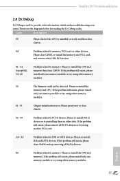
... other memory modules. 55 The Memory could not be detected. A0 - Please re-install IDE and SATA devices. Please re-install the memory and CPU. Fatal1ty Z97 Professional Series 2.8 Dr. Debug Dr. Debug is installed correctly and then clear CMOS. 0d Problem related to memory, VGA card or other slots.
... other memory modules. 55 The Memory could not be detected. A0 - Please re-install IDE and SATA devices. Please re-install the memory and CPU. Fatal1ty Z97 Professional Series 2.8 Dr. Debug Dr. Debug is installed correctly and then clear CMOS. 0d Problem related to memory, VGA card or other slots.
User Manual
Page 35
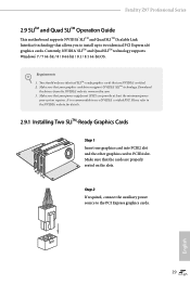
... SLITM-Ready Graphics Cards Step 1 Insert one graphics card into PCIE2 slot and the other graphics card to two identical PCI Express x16 graphics cards. Fatal1ty Z97 Professional Series 2.9 SLITM and Quad SLITM Operation Guide This motherboard supports NVIDIA® SLITM and Quad SLITM (Scalable Link Interface) technology that allows you to install...
... SLITM-Ready Graphics Cards Step 1 Insert one graphics card into PCIE2 slot and the other graphics card to two identical PCI Express x16 graphics cards. Fatal1ty Z97 Professional Series 2.9 SLITM and Quad SLITM Operation Guide This motherboard supports NVIDIA® SLITM and Quad SLITM (Scalable Link Interface) technology that allows you to install...

User Manual
Page 37
... the NVIDIA Control Panel icon in the NVIDIA® nView system tray utility. Then select Maximize 3D performance and click Apply. Step 3 Reboot your system. Fatal1ty Z97 Professional Series 2.9.2 Driver Installation and Setup Install the graphics card drivers to enable the multi-GPU. Please follow the below procedures to your system. After that...
... the NVIDIA Control Panel icon in the NVIDIA® nView system tray utility. Then select Maximize 3D performance and click Apply. Step 3 Reboot your system. Fatal1ty Z97 Professional Series 2.9.2 Driver Installation and Setup Install the graphics card drivers to enable the multi-GPU. Please follow the below procedures to your system. After that...

User Manual
Page 39
English 33 Fatal1ty Z97 Professional Series Step 3 Connect a VGA cable or a DVI cable to the monitor connector or the DVI connector of the graphics card that is inserted to PCIE2 ...
English 33 Fatal1ty Z97 Professional Series Step 3 Connect a VGA cable or a DVI cable to the monitor connector or the DVI connector of the graphics card that is inserted to PCIE2 ...

