
Intel Smart Response Installation Guide
Page 1
... setup, including installing the OS to [RAID Mode]. For the new version RST driver, please check our website for the latest information: http://www.asrock.com * Before you use the full SSD as the Cache device, which SSD you wish to use as Cache device or only 20GB, and if...GUI will update the new version RST driver in Icon tray, lower right-hand corner of the screen. 4. Intel Smart Response Technology Installation Guide This motherboard supports Intel Smart Response Technology. Once open RST GUI from either Start Menu or by step instructions below. It is not necessary to build RAID...
... setup, including installing the OS to [RAID Mode]. For the new version RST driver, please check our website for the latest information: http://www.asrock.com * Before you use the full SSD as the Cache device, which SSD you wish to use as Cache device or only 20GB, and if...GUI will update the new version RST driver in Icon tray, lower right-hand corner of the screen. 4. Intel Smart Response Technology Installation Guide This motherboard supports Intel Smart Response Technology. Once open RST GUI from either Start Menu or by step instructions below. It is not necessary to build RAID...
RAID Installation Guide
Page 2
You may install SATA hard disks on SATA ports. 2 This section will guide you how to create RAID on this guide carefully according to SATA Hard Disks Installation 1.1 Serial ATA (SATA) Hard Disks Installation Intel chipset supports Serial ATA (SATA) hard disks with RAID functions, including RAID 0, RAID 1, RAID 5, RAID 10 and Intel Rapid Storage. Please read the RAID configurations in this motherboard for internal storage devices. 1. Guide to the Intel southbridge chipset that your motherboard adopts.
You may install SATA hard disks on SATA ports. 2 This section will guide you how to create RAID on this guide carefully according to SATA Hard Disks Installation 1.1 Serial ATA (SATA) Hard Disks Installation Intel chipset supports Serial ATA (SATA) hard disks with RAID functions, including RAID 0, RAID 1, RAID 5, RAID 10 and Intel Rapid Storage. Please read the RAID configurations in this motherboard for internal storage devices. 1. Guide to the Intel southbridge chipset that your motherboard adopts.
RAID Installation Guide
Page 3
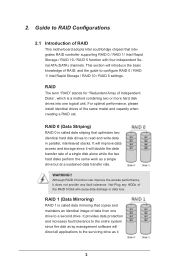
... the basic knowledge of Independent Disks", which is called data striping that optimizes two identical hard disk drives to RAID Configurations 2.1 Introduction of RAID This motherboard adopts Intel southbridge chipset that copies and maintains an identical image of the same model and capacity when creating a RAID set. WARNING!! 2. For optimal performance...
... the basic knowledge of Independent Disks", which is called data striping that optimizes two identical hard disk drives to RAID Configurations 2.1 Introduction of RAID This motherboard adopts Intel southbridge chipset that copies and maintains an identical image of the same model and capacity when creating a RAID set. WARNING!! 2. For optimal performance...
RAID Installation Guide
Page 18
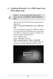
... than 2TB. STEP 1: Copy Intel® RAID drivers into a USB flash disk You can download the drivers from ASRock's website and unzip the files into a USB flash disk or copy the files from ASRock's motherboard support CD. (Please copy the files under the following directory: 32 bit: ..\i386\Win7_Intel.. 64-bit: ..\AMD64\Win7...
... than 2TB. STEP 1: Copy Intel® RAID drivers into a USB flash disk You can download the drivers from ASRock's website and unzip the files into a USB flash disk or copy the files from ASRock's motherboard support CD. (Please copy the files under the following directory: 32 bit: ..\i386\Win7_Intel.. 64-bit: ..\AMD64\Win7...
RAID Installation Guide
Page 20
... may take more time to reboot.) D. E. Please request the hotfix KB2505454 through this problem. Windows® will need to follow the instructions below to install motherboard drivers and utilities. 20 Reboot your system. (It may take a long time; >30 mins.) C. If you will install this hotfix then reboot by itself. Disk...
... may take more time to reboot.) D. E. Please request the hotfix KB2505454 through this problem. Windows® will need to follow the instructions below to install motherboard drivers and utilities. 20 Reboot your system. (It may take a long time; >30 mins.) C. If you will install this hotfix then reboot by itself. Disk...

Intel Rapid Storage Guide
Page 12
.... 3. Select the appropriate number of hard drives and press Space to select the drive. Enable RAID in System BIOS Use the instructions included with your motherboard to enable RAID in the system BIOS, a RAID volume must be created, and the F6 installation method must be used to load the Intel®...
.... 3. Select the appropriate number of hard drives and press Space to select the drive. Enable RAID in System BIOS Use the instructions included with your motherboard to enable RAID in the system BIOS, a RAID volume must be created, and the F6 installation method must be used to load the Intel®...
Quick Installation Guide
Page 1
...implied, including but not limited to the following two conditions: (1) this device may not cause harmful interference, and (2) this motherboard contains Perchlorate, a toxic substance controlled in the documentation or product. When you discard the Lithium battery in California, USA, please... a commitment by any errors or omissions that may apply, see www.dtsc.ca.gov/hazardouswaste/ perchlorate" ASRock Website: http://www.asrock.com ASRock assumes no event shall ASRock, its directors, officers, employees, or agents be reproduced, transcribed, transmitted, or translated in any language...
...implied, including but not limited to the following two conditions: (1) this device may not cause harmful interference, and (2) this motherboard contains Perchlorate, a toxic substance controlled in the documentation or product. When you discard the Lithium battery in California, USA, please... a commitment by any errors or omissions that may apply, see www.dtsc.ca.gov/hazardouswaste/ perchlorate" ASRock Website: http://www.asrock.com ASRock assumes no event shall ASRock, its directors, officers, employees, or agents be reproduced, transcribed, transmitted, or translated in any language...
Quick Installation Guide
Page 5
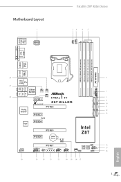
USB 2.0 T: USB0 B: USB1 PS2 Keyboard/ Mouse Motherboard Layout ATX12V1 Fatal1ty Z87 Killer Series CPU_FAN2 CPU_FAN1 DVI1 VGA1 DDR3_A1 (64 bit, 240-pin module) DDR3_A2 (64 bit, 240-pin module) DDR3_B1 (64 bit, ... CHA_FAN3 CHA_FAN2 Top: Center: SATA3_1 SATA3_0 SATA3_3 SATA3_2 Purity SoundTM PCIE1 X Fast LAN 1 FATA L PWR_FAN1 TY Z87 KILLER PCIE2 PCIE3 SATA3_5 SATA3_4 RoHS Super I/O PCIE4 PCIE5 Intel Z87 PCIE6 CMOS Battery BIOS_A_LED1 BIOS_B_LED1 CLRCMOS1 1 HD_AUDIO1 1 COM1 1 IR1 1 PCIE7 SLI/XFIRE_PWR1 USB6_7 1 USB4_5 1 CHA_FAN1 64Mb BIOS BIOS_A1 1 BIOS_SEL1 ...
USB 2.0 T: USB0 B: USB1 PS2 Keyboard/ Mouse Motherboard Layout ATX12V1 Fatal1ty Z87 Killer Series CPU_FAN2 CPU_FAN1 DVI1 VGA1 DDR3_A1 (64 bit, 240-pin module) DDR3_A2 (64 bit, 240-pin module) DDR3_B1 (64 bit, ... CHA_FAN3 CHA_FAN2 Top: Center: SATA3_1 SATA3_0 SATA3_3 SATA3_2 Purity SoundTM PCIE1 X Fast LAN 1 FATA L PWR_FAN1 TY Z87 KILLER PCIE2 PCIE3 SATA3_5 SATA3_4 RoHS Super I/O PCIE4 PCIE5 Intel Z87 PCIE6 CMOS Battery BIOS_A_LED1 BIOS_B_LED1 CLRCMOS1 1 HD_AUDIO1 1 COM1 1 IR1 1 PCIE7 SLI/XFIRE_PWR1 USB6_7 1 USB4_5 1 CHA_FAN1 64Mb BIOS BIOS_A1 1 BIOS_SEL1 ...
Quick Installation Guide
Page 9
... manual will be subject to change without further notice. ASRock website http://www.asrock.com. 1.1 Package Contents • ASRock Fatal1ty Z87 Killer Series Motherboard (ATX Form Factor) • ASRock Fatal1ty Z87 Killer Series Quick Installation Guide • ASRock Fatal1ty Z87 Killer Series Support CD • 4 x Serial ATA (SATA) Data Cables (Optional) • 1 x I/O Panel Shield • 1 x ASRock SLI_Bridge_2S Card 5 English Fatal1ty Z87 Killer Series Chapter 1 Introduction Thank you are using.
... manual will be subject to change without further notice. ASRock website http://www.asrock.com. 1.1 Package Contents • ASRock Fatal1ty Z87 Killer Series Motherboard (ATX Form Factor) • ASRock Fatal1ty Z87 Killer Series Quick Installation Guide • ASRock Fatal1ty Z87 Killer Series Support CD • 4 x Serial ATA (SATA) Data Cables (Optional) • 1 x I/O Panel Shield • 1 x ASRock SLI_Bridge_2S Card 5 English Fatal1ty Z87 Killer Series Chapter 1 Introduction Thank you are using.
Quick Installation Guide
Page 16
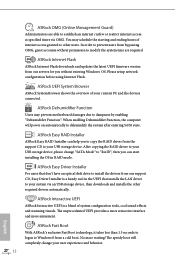
...the computer will completely change "SATA Mode" to "RAID", then you can help you to your USB storage device. ASRock Internet Flash ASRock Internet Flash downloads and updates the latest UEFI firmware version from the support CD to copy the RAID driver from our ... tools, cool sound effects and stunning visuals. ASRock Interactive UEFI ASRock Interactive UEFI is a handy tool in RAID mode. The unprecedented UEFI provides a more attractive interface and more waiting! No more amusment. You may prevent motherboard damages due to install the drivers from our support...
...the computer will completely change "SATA Mode" to "RAID", then you can help you to your USB storage device. ASRock Internet Flash ASRock Internet Flash downloads and updates the latest UEFI firmware version from the support CD to copy the RAID driver from our ... tools, cool sound effects and stunning visuals. ASRock Interactive UEFI ASRock Interactive UEFI is a handy tool in RAID mode. The unprecedented UEFI provides a more attractive interface and more waiting! No more amusment. You may prevent motherboard damages due to install the drivers from our support...
Quick Installation Guide
Page 18
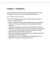
...! Pre-installation Precautions Take note of your motherboard directly on a grounded anti-static pad or in the bag that the motherboard fits into it. Chapter 2 Installation This is an ATX form factor motherboard. Before you and damages to motherboard components. • In order to avoid ...damage from static electricity to the motherboard's components, NEVER place your chassis to ensure...
...! Pre-installation Precautions Take note of your motherboard directly on a grounded anti-static pad or in the bag that the motherboard fits into it. Chapter 2 Installation This is an ATX form factor motherboard. Before you and damages to motherboard components. • In order to avoid ...damage from static electricity to the motherboard's components, NEVER place your chassis to ensure...
Quick Installation Guide
Page 21
The cover must be placed if you wish to return the motherboard for after service. 17 English Fatal1ty Z87 Killer Series Please save and replace the cover if the processor is removed.
The cover must be placed if you wish to return the motherboard for after service. 17 English Fatal1ty Z87 Killer Series Please save and replace the cover if the processor is removed.
Quick Installation Guide
Page 23
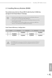
... Populated Populated DDR3_A2 Populated Populated DDR3_B1 Populated Populated DDR3_B2 Populated Populated The DIMM only fits in one or three memory module installed. 3. Fatal1ty Z87 Killer Series 2.3 Installing Memory Modules (DIMM) This motherboard provides four 240-pin DDR3 (Double Data Rate 3) DIMM slots, and supports Dual Channel Memory Technology. 1. It is not allowed to install...
... Populated Populated DDR3_A2 Populated Populated DDR3_B1 Populated Populated DDR3_B2 Populated Populated The DIMM only fits in one or three memory module installed. 3. Fatal1ty Z87 Killer Series 2.3 Installing Memory Modules (DIMM) This motherboard provides four 240-pin DDR3 (Double Data Rate 3) DIMM slots, and supports Dual Channel Memory Technology. 1. It is not allowed to install...

Quick Installation Guide
Page 25
... thermal environment, please connect a chassis fan to the motherboard's chassis fan connector (CHA_FAN1, CHA_FAN2 or CHA_FAN3) when using multiple graphics cards. PCIE4 (PCIe 2.0 x1 slots) is used for PCI Express x1 lane width cards. Fatal1ty Z87 Killer Series 2.4 Expansion Slots (PCI Express Slots) There are... 7 PCI Express slots on the motherboard. PCIE6 (PCIe 2.0 x1 slots) is used for the card before you start the installation. ...
... thermal environment, please connect a chassis fan to the motherboard's chassis fan connector (CHA_FAN1, CHA_FAN2 or CHA_FAN3) when using multiple graphics cards. PCIE4 (PCIe 2.0 x1 slots) is used for PCI Express x1 lane width cards. Fatal1ty Z87 Killer Series 2.4 Expansion Slots (PCI Express Slots) There are... 7 PCI Express slots on the motherboard. PCIE6 (PCIe 2.0 x1 slots) is used for the card before you start the installation. ...
Quick Installation Guide
Page 27
... the next system boot. However, if the main BIOS is activated currently. For the sake of your system. Fatal1ty Z87 Killer Series BIOS Selection Jumper (BIOS_SEL1) (see p.1, No. 17) Default Backup BIOS (Main BIOS) This motherboard has two BIOS onboard, a main BIOS (BIOS_A) and a backup BIOS (BIOS_B), which BIOS is corrupted or damaged, please...
... the next system boot. However, if the main BIOS is activated currently. For the sake of your system. Fatal1ty Z87 Killer Series BIOS Selection Jumper (BIOS_SEL1) (see p.1, No. 17) Default Backup BIOS (Main BIOS) This motherboard has two BIOS onboard, a main BIOS (BIOS_A) and a backup BIOS (BIOS_B), which BIOS is corrupted or damaged, please...
Quick Installation Guide
Page 28
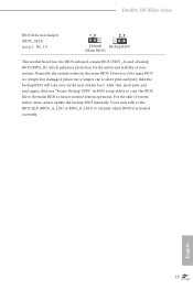
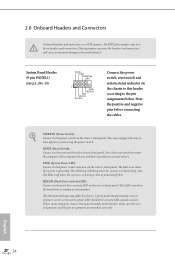
... the hard drive is in S1/S3 sleep state. Press the reset switch to restart the computer if the computer freezes and fails to the motherboard. Note the positive and negative pins before connecting the cables. 2.6 Onboard Headers and Connectors Onboard headers and connectors are matched correctly.
... the hard drive is in S1/S3 sleep state. Press the reset switch to restart the computer if the computer freezes and fails to the motherboard. Note the positive and negative pins before connecting the cables. 2.6 Onboard Headers and Connectors Onboard headers and connectors are matched correctly.
Quick Installation Guide
Page 29
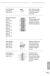
...+ Vbus IntA_PB_SSRXIntA_PB_SSRX+ GND IntA_PB_SSTXIntA_PB_SSTX+ GND IntA_PB_DIntA_PB_D+ Dummy 1 Besides four USB 3.0 ports on the I /O panel, there are two headers on this motherboard. Each USB 3.0 header can support two ports. USB 2.0 Headers (9-pin USB4_5) (see p.1, No. 20) (9-pin USB6_7) (see p.1, No. ...data transfer rate. Each USB 2.0 header can support two ports. Fatal1ty Z87 Killer Series Power LED Header (3-pin PLED1) (see p.1, No. 7) USB_PWR PP+ GND DUMMY 1 GND P+ PUSB_PWR Besides four USB 2.0 ports on the I /O panel, there is one header on this motherboard.
...+ Vbus IntA_PB_SSRXIntA_PB_SSRX+ GND IntA_PB_SSTXIntA_PB_SSTX+ GND IntA_PB_DIntA_PB_D+ Dummy 1 Besides four USB 3.0 ports on the I /O panel, there are two headers on this motherboard. Each USB 3.0 header can support two ports. USB 2.0 Headers (9-pin USB4_5) (see p.1, No. 20) (9-pin USB6_7) (see p.1, No. ...data transfer rate. Each USB 2.0 header can support two ports. Fatal1ty Z87 Killer Series Power LED Header (3-pin PLED1) (see p.1, No. 7) USB_PWR PP+ GND DUMMY 1 GND P+ PUSB_PWR Besides four USB 2.0 ports on the I /O panel, there is one header on this motherboard.
Quick Installation Guide
Page 31
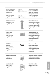
Fatal1ty Z87 Killer Series CPU Fan Connectors (4-pin CPU_FAN1) (see p.1, No. 3) (3-pin CPU_FAN2) (see p.1, No... No. 23) Serial Port Header (9-pin COM1) (see p.1, No. 24) GND +12V CPU_FAN_SPEED FAN_SPEED_CONTROL This motherboard provides a 4-Pin CPU fan (Quiet Fan) connector. To use a 4-pin ATX power supply, please plug it to Pin 1-3. ...1 power connector. Please connect this connector with a hard disk power connector when two graphics cards are installed on this motherboard. This COM1 header supports a serial port module. 27 English IRTX +5VSB DUMMY 1 GND IRRX RRXD1 DDTR#1 DDSR#1...
Fatal1ty Z87 Killer Series CPU Fan Connectors (4-pin CPU_FAN1) (see p.1, No. 3) (3-pin CPU_FAN2) (see p.1, No... No. 23) Serial Port Header (9-pin COM1) (see p.1, No. 24) GND +12V CPU_FAN_SPEED FAN_SPEED_CONTROL This motherboard provides a 4-Pin CPU fan (Quiet Fan) connector. To use a 4-pin ATX power supply, please plug it to Pin 1-3. ...1 power connector. Please connect this connector with a hard disk power connector when two graphics cards are installed on this motherboard. This COM1 header supports a serial port module. 27 English IRTX +5VSB DUMMY 1 GND IRRX RRXD1 DDTR#1 DDSR#1...


