

User Manual
Page 6
...1.2 Specifications 2 1.3 Motherboard Layout 7 1.4 I/O Panel 9 Chapter 2 Installation 11 2.1 Installing the CPU 12 2.2 Installing the CPU Fan and Heatsink 15 2.3 Installing Memory Modules (DIMM) 16 2.4 Expansion Slots (PCI Express Slots) 18 2.5 Jumpers Setup 19 2.6 Onboard Headers and Connectors 21 2.7 CrossFireXTM and Quad CrossFireXTM Operation Guide 26 2.7.1 Installing Two CrossFireXTM-Ready Graphics Cards 26 2.7.2 Driver Installation and Setup 28 2.8 M.2_SSD (NGFF) Module Installation Guide 29 Chapter 3 Software and Utilities Operation 32 3.1 Installing Drivers...
...1.2 Specifications 2 1.3 Motherboard Layout 7 1.4 I/O Panel 9 Chapter 2 Installation 11 2.1 Installing the CPU 12 2.2 Installing the CPU Fan and Heatsink 15 2.3 Installing Memory Modules (DIMM) 16 2.4 Expansion Slots (PCI Express Slots) 18 2.5 Jumpers Setup 19 2.6 Onboard Headers and Connectors 21 2.7 CrossFireXTM and Quad CrossFireXTM Operation Guide 26 2.7.1 Installing Two CrossFireXTM-Ready Graphics Cards 26 2.7.2 Driver Installation and Setup 28 2.8 M.2_SSD (NGFF) Module Installation Guide 29 Chapter 3 Software and Utilities Operation 32 3.1 Installing Drivers...

User Manual
Page 7
... 3.3.2 Using Killer Network Manager 37 3.4 ASRock Live Update & APP Shop 40 3.4.1 UI Overview 40 3.4.2 Apps 41 3.4.3 BIOS & Drivers 44 3.4.4 Setting 45 3.5 XSplit Broadcaster 46 3.5.1 Live Streaming Your Gameplay 46 3.5.2 Recording Your Gameplay 49 3.6 Enabling USB Ports for Windows® 7 Installation 50 Chapter 4 UEFI SETUP UTILITY 53 4.1 Introduction 53 4.1.1 UEFI Menu Bar 53 4.1.2 Navigation Keys 54 4.2 Main Screen 55 4.3 OC Tweaker Screen 56 4.4 Advanced Screen 66 4.4.1 CPU Configuration 67 4.4.2 Chipset Configuration 69 4.4.3 Storage Configuration...
... 3.3.2 Using Killer Network Manager 37 3.4 ASRock Live Update & APP Shop 40 3.4.1 UI Overview 40 3.4.2 Apps 41 3.4.3 BIOS & Drivers 44 3.4.4 Setting 45 3.5 XSplit Broadcaster 46 3.5.1 Live Streaming Your Gameplay 46 3.5.2 Recording Your Gameplay 49 3.6 Enabling USB Ports for Windows® 7 Installation 50 Chapter 4 UEFI SETUP UTILITY 53 4.1 Introduction 53 4.1.1 UEFI Menu Bar 53 4.1.2 Navigation Keys 54 4.2 Main Screen 55 4.3 OC Tweaker Screen 56 4.4 Advanced Screen 66 4.4.1 CPU Configuration 67 4.4.2 Chipset Configuration 69 4.4.3 Storage Configuration...
User Manual
Page 9
In this motherboard, please visit our website for specific information about the model you for M.2 Socket 1 English Chapter 3 contains the operation guide of the BIOS setup. You may find the latest VGA cards and CPU support list on ASRock's website without notice. In case any modifications of this documentation will be subject to change without further notice. Fatal1ty Z170 Gaming K4 Series Chapter 1 Introduction Thank you are using. It delivers excellent performance...
In this motherboard, please visit our website for specific information about the model you for M.2 Socket 1 English Chapter 3 contains the operation guide of the BIOS setup. You may find the latest VGA cards and CPU support list on ASRock's website without notice. In case any modifications of this documentation will be subject to change without further notice. Fatal1ty Z170 Gaming K4 Series Chapter 1 Introduction Thank you are using. It delivers excellent performance...

User Manual
Page 11
... memory 1792MB • Dual graphics output: Support DVI-D and HDMI ports by independent display controllers • Supports HDMI with AVC, MVC (S3D) and MPEG-2 Full HW Encode1, Intel® InTruTM 3D, Intel® Clear Video HD Technology, Intel® InsiderTM, Intel® HD Graphics 510/530 • Pixel Shader 5.0, DirectX 12 • Max. Direct Drive Technology - Fatal1ty Z170 Gaming K4 Series Audio • Supports Intel® HD Graphics Built-in Visuals : Intel® Quick Sync Video...
... memory 1792MB • Dual graphics output: Support DVI-D and HDMI ports by independent display controllers • Supports HDMI with AVC, MVC (S3D) and MPEG-2 Full HW Encode1, Intel® InTruTM 3D, Intel® Clear Video HD Technology, Intel® InsiderTM, Intel® HD Graphics 510/530 • Pixel Shader 5.0, DirectX 12 • Max. Direct Drive Technology - Fatal1ty Z170 Gaming K4 Series Audio • Supports Intel® HD Graphics Built-in Visuals : Intel® Quick Sync Video...
User Manual
Page 13
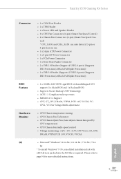
... auto detect if 3-pin or 4-pin fan is in use. • 1 x 24 pin ATX Power Connector • 1 x 8 pin 12V Power Connector • 1 x PCIe Power Connector • 1 x Front Panel Audio Connector • 2 x USB 2.0 Headers (Support 4 USB 2.0 ports) (Supports ESD Protection (ASRock Full Spike Protection)) • 1 x USB 3.0 Header (Supports 2 USB 3.0 ports) (Supports ESD Protection (ASRock Full Spike Protection)) BIOS Feature • 2 x 128Mb AMI UEFI Legal BIOS with xHCI drivers packed into the ISO file is required. bit * To install Windows® 7 OS, a modified installation disk...
... auto detect if 3-pin or 4-pin fan is in use. • 1 x 24 pin ATX Power Connector • 1 x 8 pin 12V Power Connector • 1 x PCIe Power Connector • 1 x Front Panel Audio Connector • 2 x USB 2.0 Headers (Support 4 USB 2.0 ports) (Supports ESD Protection (ASRock Full Spike Protection)) • 1 x USB 3.0 Header (Supports 2 USB 3.0 ports) (Supports ESD Protection (ASRock Full Spike Protection)) BIOS Feature • 2 x 128Mb AMI UEFI Legal BIOS with xHCI drivers packed into the ISO file is required. bit * To install Windows® 7 OS, a modified installation disk...

User Manual
Page 16
... Connectors (SATA3_0_1) 9 CPU Fan Connector (CPU_FAN2) 10 SATA3 Connectors (SATA3_3_5) 11 SATA3 Connectors (SATA3_2_4) 12 Chassis Fan Connector (CHA_FAN2) 13 Chassis Fan Connector (CHA_FAN1) 14 SATA Express Connectors (SATA3_2_3 / SATA3_4_5) 15 System Panel Header (PANEL1) 16 Clear CMOS Jumper (CLRMOS1) 17 Power LED and Speaker Header (SPK_PLED1) 18 USB 2.0 Header (USB1_2) 19 USB 2.0 Header (USB3_4) 20 BIOS Selection Jumper (BIOS_SEL1) 21 Chassis Fan Connector (CHA_FAN3) 22 TPM Header (TPMS1) 23 COM Port Header (COM1) 24 Front Panel Audio Header (HD_AUDIO1) 25 PCIe Power Connector (PCIE_PWR1...
... Connectors (SATA3_0_1) 9 CPU Fan Connector (CPU_FAN2) 10 SATA3 Connectors (SATA3_3_5) 11 SATA3 Connectors (SATA3_2_4) 12 Chassis Fan Connector (CHA_FAN2) 13 Chassis Fan Connector (CHA_FAN1) 14 SATA Express Connectors (SATA3_2_3 / SATA3_4_5) 15 System Panel Header (PANEL1) 16 Clear CMOS Jumper (CLRMOS1) 17 Power LED and Speaker Header (SPK_PLED1) 18 USB 2.0 Header (USB1_2) 19 USB 2.0 Header (USB3_4) 20 BIOS Selection Jumper (BIOS_SEL1) 21 Chassis Fan Connector (CHA_FAN3) 22 TPM Header (TPMS1) 23 COM Port Header (COM1) 24 Front Panel Audio Header (HD_AUDIO1) 25 PCIe Power Connector (PCIE_PWR1...

User Manual
Page 26
... installation. PCIe slots: PCIE1 (PCIe 3.0 x1 slot) is used for PCI Express x4 lane width graphics cards. PCIE3 (PCIe 3.0 x1 slot) is used for PCI Express x16 lane width graphics cards. PCIE2 (PCIe 3.0 x16 slot) is used for PCI Express x1 lane width cards. For a better thermal environment, please connect a chassis fan to the motherboard's chassis fan connector (CHA_FAN1, CHA_FAN2, CHA_FAN3 or CHA_FAN4) when using multiple graphics cards. 18 English Please read the documentation of the expansion card and make sure that the power supply is switched...
... installation. PCIe slots: PCIE1 (PCIe 3.0 x1 slot) is used for PCI Express x4 lane width graphics cards. PCIE3 (PCIe 3.0 x1 slot) is used for PCI Express x16 lane width graphics cards. PCIE2 (PCIe 3.0 x16 slot) is used for PCI Express x1 lane width cards. For a better thermal environment, please connect a chassis fan to the motherboard's chassis fan connector (CHA_FAN1, CHA_FAN2, CHA_FAN3 or CHA_FAN4) when using multiple graphics cards. 18 English Please read the documentation of the expansion card and make sure that the power supply is switched...
User Manual
Page 27
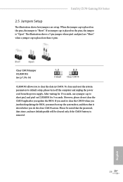
... you update the BIOS. Please be noted that the password, date, time, and user default profile will be cleared only if the CMOS battery is placed on CLRMOS1 for 15 seconds, use a jumper cap to short pin2 and pin3 on these 2 pins. Fatal1ty Z170 Gaming K4 Series 2.5 Jumpers Setup The illustration shows how jumpers are "Short" when a jumper cap is removed. When the jumper cap is placed on the pins, the jumper is "Short". To clear and reset the...
... you update the BIOS. Please be noted that the password, date, time, and user default profile will be cleared only if the CMOS battery is placed on CLRMOS1 for 15 seconds, use a jumper cap to short pin2 and pin3 on these 2 pins. Fatal1ty Z170 Gaming K4 Series 2.5 Jumpers Setup The illustration shows how jumpers are "Short" when a jumper cap is removed. When the jumper cap is placed on the pins, the jumper is "Short". To clear and reset the...

User Manual
Page 29
... the hard drive is operating. Fatal1ty Z170 Gaming K4 Series 2.6 Onboard Headers and Connectors Onboard headers and connectors are matched correctly. The front panel design may configure the way to the power status indicator on the chassis front panel. Note the positive and negative pins before connecting the cables. The LED is on when the system is reading or writing data. HDLED (Hard Drive Activity LED): Connect to perform a normal restart. A front panel module mainly consists of power switch, reset switch, power LED, hard drive activity LED, speaker...
... the hard drive is operating. Fatal1ty Z170 Gaming K4 Series 2.6 Onboard Headers and Connectors Onboard headers and connectors are matched correctly. The front panel design may configure the way to the power status indicator on the chassis front panel. Note the positive and negative pins before connecting the cables. The LED is on when the system is reading or writing data. HDLED (Hard Drive Activity LED): Connect to perform a normal restart. A front panel module mainly consists of power switch, reset switch, power LED, hard drive activity LED, speaker...
User Manual
Page 31
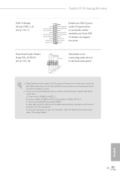
High Definition Audio supports Jack Sensing, but the panel wire on the chassis must support HDA to MIC2_L. Connect Mic_IN (MIC) to function correctly. Fatal1ty Z170 Gaming K4 Series USB 3.0 Header (19-pin USB3_7_8) (see p.7, No. 24) GND PRESENCE# MIC_RET OUT_RET 1 OUT2_L J_SENSE OUT2_R MIC2_R MIC2_L This header is one header on this IntA_PB_SSTX- Connect Ground (GND) to install your system. 2. English 23 IntA_PB_SSTX+ motherboard. Please follow the instructions in the Realtek Control panel and...
High Definition Audio supports Jack Sensing, but the panel wire on the chassis must support HDA to MIC2_L. Connect Mic_IN (MIC) to function correctly. Fatal1ty Z170 Gaming K4 Series USB 3.0 Header (19-pin USB3_7_8) (see p.7, No. 24) GND PRESENCE# MIC_RET OUT_RET 1 OUT2_L J_SENSE OUT2_R MIC2_R MIC2_L This header is one header on this IntA_PB_SSTX- Connect Ground (GND) to install your system. 2. English 23 IntA_PB_SSTX+ motherboard. Please follow the instructions in the Realtek Control panel and...

User Manual
Page 33
... +12V DETECT Please connect a 4 pin molex power cable to this connector when more than three graphics cards are installed. A TPM system also helps enhance network security, protects digital identities, and ensures platform integrity. This connector supports Trusted Platform Module (TPM) system, 1 which can securely store keys, digital certificates, passwords, and data. Fatal1ty Z170 Gaming K4 Series Serial Port Header (9-pin COM1) (see p.7, No. 23) TPM Header (17-pin TPMS1) (see p.7, No. 22) PCIe Power Connector (4-pin PCIE_PWR1) (see...
... +12V DETECT Please connect a 4 pin molex power cable to this connector when more than three graphics cards are installed. A TPM system also helps enhance network security, protects digital identities, and ensures platform integrity. This connector supports Trusted Platform Module (TPM) system, 1 which can securely store keys, digital certificates, passwords, and data. Fatal1ty Z170 Gaming K4 Series Serial Port Header (9-pin COM1) (see p.7, No. 23) TPM Header (17-pin TPMS1) (see p.7, No. 22) PCIe Power Connector (4-pin PCIE_PWR1) (see...

User Manual
Page 34
... you to install up to AMD graphics card manuals for details. 4. Please refer to three identical PCI Express x16 graphics cards. 1. Step 2 Connect two graphics cards by installing a CrossFire Bridge on the CrossFire Bridge Interconnects on the slots. Please refer to the AMD's website for detailed installation guide. 2.7.1 Installing Two CrossFireXTM-Ready Graphics Cards CrossFire Bridge Step 1 Insert one graphics card into PCIE2 slot and the other graphics card to use identical CrossFireXTM-ready graphics cards that are...
... you to install up to AMD graphics card manuals for details. 4. Please refer to three identical PCI Express x16 graphics cards. 1. Step 2 Connect two graphics cards by installing a CrossFire Bridge on the CrossFire Bridge Interconnects on the slots. Please refer to the AMD's website for detailed installation guide. 2.7.1 Installing Two CrossFireXTM-Ready Graphics Cards CrossFire Bridge Step 1 Insert one graphics card into PCIE2 slot and the other graphics card to use identical CrossFireXTM-ready graphics cards that are...
User Manual
Page 36
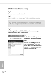
... computer and boot into OS. Then select Enable AMD CrossFireX and click Apply. The Catalyst Uninstaller is an optional download. Step 5 In the left pane, click Performance and then AMD CrossFireXTM. English 28 Select the GPU number according to installation. AMD Catalyst Control Center Step 4 Double-click the AMD Catalyst Control Center icon in your graphics card and click Apply. 2.7.2 Driver Installation and Setup Step 1 Power on...
... computer and boot into OS. Then select Enable AMD CrossFireX and click Apply. The Catalyst Uninstaller is an optional download. Step 5 In the left pane, click Performance and then AMD CrossFireXTM. English 28 Select the GPU number according to installation. AMD Catalyst Control Center Step 4 Double-click the AMD Catalyst Control Center icon in your graphics card and click Apply. 2.7.2 Driver Installation and Setup Step 1 Power on...
User Manual
Page 40
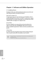
...-us 32 English Therefore, the drivers you install can work properly. Utilities Menu The Utilities Menu shows the application software that enhance the motherboard's features. Please click Install All or follow the installation wizard to display the menu. Click on a specific item then follow the order from top to bottom to your system will be auto-detected and listed on the file "ASRSETUP.EXE" in your CD-ROM drive.
...-us 32 English Therefore, the drivers you install can work properly. Utilities Menu The Utilities Menu shows the application software that enhance the motherboard's features. Please click Install All or follow the installation wizard to display the menu. Click on a specific item then follow the order from top to bottom to your system will be auto-detected and listed on the file "ASRSETUP.EXE" in your CD-ROM drive.

User Manual
Page 41
... main menu: Operation Mode, OC Tweaker, System Info, FAN-Tastic Tuning, Tech Service and Settings. Fatal1ty Z170 Gaming K4 Series 3.2 F-Stream F-Stream is ASRock's multi purpose software suite with a new interface, more new features and improved utilities. 3.2.1 Installing F-Stream When you will find the icon "F-Stream" on your system from ASRock's support CD, F-Stream will pop up. 3.2.2 Using F-Stream There are six sections in -one driver to your desktop. Operation Mode...
... main menu: Operation Mode, OC Tweaker, System Info, FAN-Tastic Tuning, Tech Service and Settings. Fatal1ty Z170 Gaming K4 Series 3.2 F-Stream F-Stream is ASRock's multi purpose software suite with a new interface, more new features and improved utilities. 3.2.1 Installing F-Stream When you will find the icon "F-Stream" on your system from ASRock's support CD, F-Stream will pop up. 3.2.2 Using F-Stream There are six sections in -one driver to your desktop. Operation Mode...

User Manual
Page 58
... use the new patched Windows® 7 installation USB drive to disabled after the installation. USB3.0). Please set PS/S Simulator back to install Windows® 7 OS. 50 English Requirements • A Windows® 7 installation disk or USB drive • USB 3.0 drivers (included in the ASRock Support CD or website) • A Windows® PC • Win7 USB Patcher (included in UEFI SETUP UTILITY > Advanced > USB Configuration, which allows the USB port to function as a PS/2 port, and then you can skip the instructions...
... use the new patched Windows® 7 installation USB drive to disabled after the installation. USB3.0). Please set PS/S Simulator back to install Windows® 7 OS. 50 English Requirements • A Windows® 7 installation disk or USB drive • USB 3.0 drivers (included in the ASRock Support CD or website) • A Windows® PC • Win7 USB Patcher (included in UEFI SETUP UTILITY > Advanced > USB Configuration, which allows the USB port to function as a PS/2 port, and then you can skip the instructions...
User Manual
Page 59
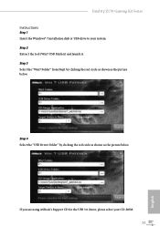
Step 2 Extract the tool (Win7 USB Patcher) and launch it. Step 3 Select the "Win7 Folder" from Step1 by clicking the red circle as shown as the picture below . If you are using ASRock's Support CD for the USB 3.0 driver, please select your system. Step 4 Select the "USB Driver Folder" by clicking the red circle as shown as the picture below . Fatal1ty Z170 Gaming K4 Series Instructions Step 1 Insert the Windows® 7 installation disk or USB drive to your CD-ROM. 51 English
Step 2 Extract the tool (Win7 USB Patcher) and launch it. Step 3 Select the "Win7 Folder" from Step1 by clicking the red circle as shown as the picture below . If you are using ASRock's Support CD for the USB 3.0 driver, please select your system. Step 4 Select the "USB Driver Folder" by clicking the red circle as shown as the picture below . Fatal1ty Z170 Gaming K4 Series Instructions Step 1 Insert the Windows® 7 installation disk or USB drive to your CD-ROM. 51 English

User Manual
Page 78
... Panel Enable/disable front panel HD audio. If [Power Off] is installed. Select enable to the integrated graphics processor when the system boots up when the power recovers. 70 English Killer E2400 PCIE Ethernet Controller Enable or disable the onboard network interface controller. Deep Sleep Configure deep sleep mode for lower power consumption. Share Memory Configure the size of the DMI Link. Render Standby Power down . If [Power On] is selected, the system will remain off when the power recovers. Set...
... Panel Enable/disable front panel HD audio. If [Power Off] is installed. Select enable to the integrated graphics processor when the system boots up when the power recovers. 70 English Killer E2400 PCIE Ethernet Controller Enable or disable the onboard network interface controller. Deep Sleep Configure deep sleep mode for lower power consumption. Share Memory Configure the size of the DMI Link. Render Standby Power down . If [Power On] is selected, the system will remain off when the power recovers. Set...
User Manual
Page 87
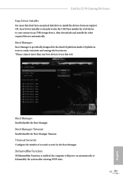
... the dual OS platform/multi-OS platform users to easily customize and manage the boot menu. *Please connect more than one boot devices to use this tool. Boot Manager Timeout Enable/disable the Boot Manager Timeout. Fatal1ty Z170 Gaming K4 Series Easy Driver Installer For users that don't have an optical disk drive to install the drivers from our support CD, Easy Driver Installer is a handy tool in the UEFI that installs the LAN driver to dehumidify the system after entering S4...
... the dual OS platform/multi-OS platform users to easily customize and manage the boot menu. *Please connect more than one boot devices to use this tool. Boot Manager Timeout Enable/disable the Boot Manager Timeout. Fatal1ty Z170 Gaming K4 Series Easy Driver Installer For users that don't have an optical disk drive to install the drivers from our support CD, Easy Driver Installer is a handy tool in the UEFI that installs the LAN driver to dehumidify the system after entering S4...

User Manual
Page 88
... the fan speed. Internet Flash - DHCP (Auto IP), Auto ASRock Internet Flash downloads and updates the latest UEFI firmware version from our servers for you. Please setup network configuration before using Internet Flash. *For BIOS backup and recovery purpose, it returns to plug in your USB storage device and run Instant Flash to the secondary flash ROM. 80 English Dehumidifier Duration Configure the duration of the CPU fan while Dehumidifier is recommended to S4/S5 state. Dehumidifier CPU Fan Setting Configure the speed of...
... the fan speed. Internet Flash - DHCP (Auto IP), Auto ASRock Internet Flash downloads and updates the latest UEFI firmware version from our servers for you. Please setup network configuration before using Internet Flash. *For BIOS backup and recovery purpose, it returns to plug in your USB storage device and run Instant Flash to the secondary flash ROM. 80 English Dehumidifier Duration Configure the duration of the CPU fan while Dehumidifier is recommended to S4/S5 state. Dehumidifier CPU Fan Setting Configure the speed of...


