
User Manual
Page 6
...Package Contents 1 1.2 Specifications 2 1.3 Motherboard Layout 6 1.4 I/O Panel 9 Chapter 2 Installation 11 2.1 Installing the CPU 12 2.2 Installing the CPU Fan and Heatsink 15 2.3 Installation of Memory Modules (DIMM) 16 2.4 Expansion Slots (PCI Express Slots) 18 2.5 Jumpers Setup 20 2.6 Onboard Headers and Connectors 21 2.7 Smart Switches 26 2.8 Dr. Debug 27 2.9 SLITM , 3-Way SLITMand Quad SLITM Operation Guide 29 2.9.1 Installing Two SLITM-Ready Graphics Cards 29 2.9.2 Installing Three SLITM-Ready Graphics Cards 31 2.9.3 Driver Installation and Setup 33 2.10...
...Package Contents 1 1.2 Specifications 2 1.3 Motherboard Layout 6 1.4 I/O Panel 9 Chapter 2 Installation 11 2.1 Installing the CPU 12 2.2 Installing the CPU Fan and Heatsink 15 2.3 Installation of Memory Modules (DIMM) 16 2.4 Expansion Slots (PCI Express Slots) 18 2.5 Jumpers Setup 20 2.6 Onboard Headers and Connectors 21 2.7 Smart Switches 26 2.8 Dr. Debug 27 2.9 SLITM , 3-Way SLITMand Quad SLITM Operation Guide 29 2.9.1 Installing Two SLITM-Ready Graphics Cards 29 2.9.2 Installing Three SLITM-Ready Graphics Cards 31 2.9.3 Driver Installation and Setup 33 2.10...
User Manual
Page 9
...-PCIe Slot 1 English ASRock website http://www.asrock.com. 1.1 Package Contents • ASRock Fatal1ty X99X Killer Series Motherboard (ATX Form Factor) • ASRock Fatal1ty X99X Killer Series Quick Installation Guide • ASRock Fatal1ty X99X Killer Series Support CD • 1 x I/O Panel Shield • 1 x ASRock SLI_Bridge_2S Card • 1 x ASRock 3-Way SLI-2S1S Bridge Card • 4 x Serial ATA (SATA) Data Cables (Optional) • 1 x HDD Saver Cable • 1 x Screw for Ultra M.2 Socket • 1 x Screw for specific information about the model you for purchasing ASRock...
...-PCIe Slot 1 English ASRock website http://www.asrock.com. 1.1 Package Contents • ASRock Fatal1ty X99X Killer Series Motherboard (ATX Form Factor) • ASRock Fatal1ty X99X Killer Series Quick Installation Guide • ASRock Fatal1ty X99X Killer Series Support CD • 1 x I/O Panel Shield • 1 x ASRock SLI_Bridge_2S Card • 1 x ASRock 3-Way SLI-2S1S Bridge Card • 4 x Serial ATA (SATA) Data Cables (Optional) • 1 x HDD Saver Cable • 1 x Screw for Ultra M.2 Socket • 1 x Screw for specific information about the model you for purchasing ASRock...

User Manual
Page 12
... PCI Express module up to Gen3 x4 (32 Gb/s) Connector • 1 x COM Port Header • 1 x TPM Header • 1 x Power LED Header • 2 x CPU Fan Connectors (1 x 4-pin, 1 x 3-pin) • 3 x Chassis Fan Connectors (1 x 4-pin, 2 x 3-pin) (Smart Fan Speed Control) • 1 x Power Fan Connector (3-pin) • 1 x 24 pin ATX Power Connector • 1 x 8 pin 12V Power Connector (Hi-Density Power Connector) • 1 x HDD Saver Connector • 1 x PCIe Power Connector • 1 x Front Panel Audio Connector • 1 x Thunderbolt AIC Connector • 2 x USB 2.0 Headers (support...
... PCI Express module up to Gen3 x4 (32 Gb/s) Connector • 1 x COM Port Header • 1 x TPM Header • 1 x Power LED Header • 2 x CPU Fan Connectors (1 x 4-pin, 1 x 3-pin) • 3 x Chassis Fan Connectors (1 x 4-pin, 2 x 3-pin) (Smart Fan Speed Control) • 1 x Power Fan Connector (3-pin) • 1 x 24 pin ATX Power Connector • 1 x 8 pin 12V Power Connector (Hi-Density Power Connector) • 1 x HDD Saver Connector • 1 x PCIe Power Connector • 1 x Front Panel Audio Connector • 1 x Thunderbolt AIC Connector • 2 x USB 2.0 Headers (support...
User Manual
Page 13
... actual memory size may affect your system's stability, or even cause damage to utilize the memory that there is a certain risk involved with multilingual GUI support (1 x Main BIOS and 1 x Backup BIOS) • Supports Secure Backup UEFI Technology • ACPI 1.1 Compliant wake up events • SMBIOS 2.3.1 Support • CPU, DRAM, PCH 1.05V, PCH 1.5V, VPPM Voltage Multi- adjustment • CPU/Chassis temperature sensing • CPU/Chassis/Power Fan Tachometer • CPU/Chassis Quiet Fan (Auto adjust chassis fan speed by overclocking. You can use . Overclocking...
... actual memory size may affect your system's stability, or even cause damage to utilize the memory that there is a certain risk involved with multilingual GUI support (1 x Main BIOS and 1 x Backup BIOS) • Supports Secure Backup UEFI Technology • ACPI 1.1 Compliant wake up events • SMBIOS 2.3.1 Support • CPU, DRAM, PCH 1.05V, PCH 1.5V, VPPM Voltage Multi- adjustment • CPU/Chassis temperature sensing • CPU/Chassis/Power Fan Tachometer • CPU/Chassis Quiet Fan (Auto adjust chassis fan speed by overclocking. You can use . Overclocking...

User Manual
Page 15
...) 15 SATA3 Connectors (SATA3_0_3) 16 SATA3 Connectors (SATA3_1_4) 17 SATA3 Connectors (SATA3_2_5) 18 Power LED Header (PLED1) 19 Chassis Speaker Header (SPEAKER1) 20 System Panel Header (PANEL1) 21 Power Switch (PWRBTN1) 22 HDD Saver Connector (SATA_PWR_1) 23 Reset Switch (RSTBTN1) 24 Chassis Fan Connector (CHA_FAN2) 25 Chassis Fan Connector (CHA_FAN1) 26 USB 2.0 Header (USB3_4) 27 USB 2.0 Header (USB5_6) 28 BIOS Selection Switch (BIOS_SEL1) 29 Clear CMOS Jumper (CLRCMOS1) 30 COM Port Header (COM1) 31 Thunderbolt AIC Connector (TBT1) 32 TPM Header (TPMS1) 33 Front Panel Audio Header (HD_AUDIO1...
...) 15 SATA3 Connectors (SATA3_0_3) 16 SATA3 Connectors (SATA3_1_4) 17 SATA3 Connectors (SATA3_2_5) 18 Power LED Header (PLED1) 19 Chassis Speaker Header (SPEAKER1) 20 System Panel Header (PANEL1) 21 Power Switch (PWRBTN1) 22 HDD Saver Connector (SATA_PWR_1) 23 Reset Switch (RSTBTN1) 24 Chassis Fan Connector (CHA_FAN2) 25 Chassis Fan Connector (CHA_FAN1) 26 USB 2.0 Header (USB3_4) 27 USB 2.0 Header (USB5_6) 28 BIOS Selection Switch (BIOS_SEL1) 29 Clear CMOS Jumper (CLRCMOS1) 30 COM Port Header (COM1) 31 Thunderbolt AIC Connector (TBT1) 32 TPM Header (TPMS1) 33 Front Panel Audio Header (HD_AUDIO1...

User Manual
Page 32
... motherboard provides a 4-Pin CPU fan (Quiet Fan) connector. To use a 4-pin ATX power supply, please plug it along Pin 1 and Pin 13. Please connect the HDD Saver Cable to this connector to Pin 1-3. If you plan to connect a 3-Pin CPU fan, please connect it along Pin 1 and Pin 5. Please connect a 4 pin molex power cable to this connector when more than three graphics cards are installed. Please connect a Thunderbolt™ add-in card (AIC) to this connector via the GPIO cable. 24 English This motherboard provides an 8-pin ATX 12V power connector. CPU Fan Connectors...
... motherboard provides a 4-Pin CPU fan (Quiet Fan) connector. To use a 4-pin ATX power supply, please plug it along Pin 1 and Pin 13. Please connect the HDD Saver Cable to this connector to Pin 1-3. If you plan to connect a 3-Pin CPU fan, please connect it along Pin 1 and Pin 5. Please connect a 4 pin molex power cable to this connector when more than three graphics cards are installed. Please connect a Thunderbolt™ add-in card (AIC) to this connector via the GPIO cable. 24 English This motherboard provides an 8-pin ATX 12V power connector. CPU Fan Connectors...
User Manual
Page 35
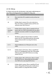
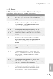
... using another VGA card. Please clear CMOS, re-install the memory and VGA card, and remove other slots. Please re-install IDE and SATA devices. If the problem still exists, please install only one memory module or try using other memory modules. 61 - 91 Chipset initialization error. Code Description 00 Please check if the CPU is used to memory. Please re-install the CPU and memory then clear CMOS. Please re-install the CPU and memory. Fatal1ty X99X Killer Series 2.8 Dr. Debug Dr. Debug is installed correctly and then clear CMOS...
... using another VGA card. Please clear CMOS, re-install the memory and VGA card, and remove other slots. Please re-install IDE and SATA devices. If the problem still exists, please install only one memory module or try using other memory modules. 61 - 91 Chipset initialization error. Code Description 00 Please check if the CPU is used to memory. Please re-install the CPU and memory then clear CMOS. Please re-install the CPU and memory. Fatal1ty X99X Killer Series 2.8 Dr. Debug Dr. Debug is installed correctly and then clear CMOS...

User Manual
Page 42
... PCI Express x16 graphics cards. Make sure that your system requires. Make sure that your power supply unit (PSU) can provide at least the minimum power your graphics card driver supports AMD CrossFireXTM technology. Download the drivers from the AMD's website: www.amd.com 3. 2.10 CrossFireXTM, 3-Way CrossFireXTM and Quad CrossFireXTM Operation Guide This motherboard supports CrossFireXTM, 3-way CrossFireXTM and Quad CrossFireXTM that are AMD certified. 2. CrossFire Bridge Step 2 Connect two graphics cards by installing...
... PCI Express x16 graphics cards. Make sure that your system requires. Make sure that your power supply unit (PSU) can provide at least the minimum power your graphics card driver supports AMD CrossFireXTM technology. Download the drivers from the AMD's website: www.amd.com 3. 2.10 CrossFireXTM, 3-Way CrossFireXTM and Quad CrossFireXTM Operation Guide This motherboard supports CrossFireXTM, 3-way CrossFireXTM and Quad CrossFireXTM that are AMD certified. 2. CrossFire Bridge Step 2 Connect two graphics cards by installing...

User Manual
Page 45
... your computer and boot into OS. Select the GPU number according to installation. Then select Enable AMD CrossFireX and click Apply. Step 3 Install the required drivers and CATALYST Control Center then restart your system. Step 5 In the left pane, click Performance and then AMD CrossFireXTM. Fatal1ty X99X Killer Series 2.10.3 Driver Installation and Setup Step 1 Power on your graphics card and click Apply. The Catalyst Uninstaller is an optional download.
... your computer and boot into OS. Select the GPU number according to installation. Then select Enable AMD CrossFireX and click Apply. Step 3 Install the required drivers and CATALYST Control Center then restart your system. Step 5 In the left pane, click Performance and then AMD CrossFireXTM. Fatal1ty X99X Killer Series 2.10.3 Driver Installation and Setup Step 1 Power on your graphics card and click Apply. The Catalyst Uninstaller is an optional download.
User Manual
Page 50
... installation wizard to display the menu. Therefore, the drivers you install can work properly. Utilities Menu The Utilities Menu shows the application software that enhance the motherboard's features. If the Main Menu does not appear automatically, locate and double click on a specific item then follow the order from top to bottom to your system will be auto-detected and listed on the support CD driver page. The CD automatically displays the Main Menu...
... installation wizard to display the menu. Therefore, the drivers you install can work properly. Utilities Menu The Utilities Menu shows the application software that enhance the motherboard's features. If the Main Menu does not appear automatically, locate and double click on a specific item then follow the order from top to bottom to your system will be auto-detected and listed on the support CD driver page. The CD automatically displays the Main Menu...

User Manual
Page 98
...Set to Auto to boot up when the power recovers. It will start to enable onboard HD audio and automatically disable it when a sound card is installed. Good Night LED By enabling Good Night LED, the Power/HDD LEDs will remain off the Power and Keyboard LEDs when the system enters into Standby/Hibernation mode. Qualcomn Atheros PCIE Ethernet Connection Controller Enable or disable the onboard network interface controller (Qualcomm® Atheros® KillerTM E2200 Series) Onboard HD Audio Enable/disable onboard HD audio. Onboard Debug Port LED Enable/disable the onboard Dr. Debug LED...
...Set to Auto to boot up when the power recovers. It will start to enable onboard HD audio and automatically disable it when a sound card is installed. Good Night LED By enabling Good Night LED, the Power/HDD LEDs will remain off the Power and Keyboard LEDs when the system enters into Standby/Hibernation mode. Qualcomn Atheros PCIE Ethernet Connection Controller Enable or disable the onboard network interface controller (Qualcomm® Atheros® KillerTM E2200 Series) Onboard HD Audio Enable/disable onboard HD audio. Onboard Debug Port LED Enable/disable the onboard Dr. Debug LED...

User Manual
Page 102
... USB 3.0 devices. Select UEFI Setup Only to disable legacy USB support. Set [Enabled] to keep the USB 3.0 driver enabled after entering the OS (USB 3.0 is enabled in BIOS). If you encounter USB compatibility issues it is recommended to support USB devices under the UEFI setup and Windows/Linux operating systems only. Set [Smart Auto] to automatically enable the USB 3.0 driver after rebooting (USB 3.0 is disabled in BIOS). Set [Auto] to keep the USB 3.0 driver enabled (Must install driver to disable the USB 3.0 ports. 4.4.6 USB Configuration USB Controller Enable...
... USB 3.0 devices. Select UEFI Setup Only to disable legacy USB support. Set [Enabled] to keep the USB 3.0 driver enabled after entering the OS (USB 3.0 is enabled in BIOS). If you encounter USB compatibility issues it is recommended to support USB devices under the UEFI setup and Windows/Linux operating systems only. Set [Smart Auto] to automatically enable the USB 3.0 driver after rebooting (USB 3.0 is disabled in BIOS). Set [Auto] to keep the USB 3.0 driver enabled (Must install driver to disable the USB 3.0 ports. 4.4.6 USB Configuration USB Controller Enable...

User Manual
Page 106
Please setup network configuration before using Internet Flash. *For BIOS backup and recovery purpose, it is recommended to update your USB pen drive before using UEFI Tech Service. Re-detect SATA Power Connection Re-detect your USB storage device. You can start installing the operating system in your UEFI. Easy Driver Installer For users that installs the LAN driver to plug in RAID mode. Instant Flash Save UEFI files in the UEFI that don't have an optical disk drive to install the drivers from our support CD, Easy Driver Installer is a handy tool...
Please setup network configuration before using Internet Flash. *For BIOS backup and recovery purpose, it is recommended to update your USB pen drive before using UEFI Tech Service. Re-detect SATA Power Connection Re-detect your USB storage device. You can start installing the operating system in your UEFI. Easy Driver Installer For users that installs the LAN driver to plug in RAID mode. Instant Flash Save UEFI files in the UEFI that don't have an optical disk drive to install the drivers from our support CD, Easy Driver Installer is a handy tool...

User Manual
Page 107
Fatal1ty X99X Killer Series Network Configuration Use this to save your settings as user default. Save User Default Type a profile name and press enter to configure internet connection settings for Internet Flash. Load User Default Load previously saved user defaults. 99 English UEFI Download Server Select a server to download the UEFI firmware. Internet Setting Enable or disable sound effects in the setup utility.
Fatal1ty X99X Killer Series Network Configuration Use this to save your settings as user default. Save User Default Type a profile name and press enter to configure internet connection settings for Internet Flash. Load User Default Load previously saved user defaults. 99 English UEFI Download Server Select a server to download the UEFI firmware. Internet Setting Enable or disable sound effects in the setup utility.

Quick Installation Guide
Page 6
... (SATA3_0_3) 16 SATA3 Connectors (SATA3_1_4) 17 SATA3 Connectors (SATA3_2_5) 18 Power LED Header (PLED1) 19 Chassis Speaker Header (SPEAKER1) 20 System Panel Header (PANEL1) 21 Power Switch (PWRBTN1) 22 HDD Saver Connector (SATA_PWR_1) 23 Reset Switch (RSTBTN1) 24 Chassis Fan Connector (CHA_FAN2) 25 Chassis Fan Connector (CHA_FAN1) 26 USB 2.0 Header (USB3_4) 27 USB 2.0 Header (USB5_6) 28 BIOS Selection Switch (BIOS_SEL1) 29 Clear CMOS Jumper (CLRCMOS1) 30 COM Port Header (COM1) 31 hunderbolt AIC Connector (TBT1) 32 TPM Header (TPMS1) 33 Front Panel Audio Header (HD_AUDIO1) 2 English No...
... (SATA3_0_3) 16 SATA3 Connectors (SATA3_1_4) 17 SATA3 Connectors (SATA3_2_5) 18 Power LED Header (PLED1) 19 Chassis Speaker Header (SPEAKER1) 20 System Panel Header (PANEL1) 21 Power Switch (PWRBTN1) 22 HDD Saver Connector (SATA_PWR_1) 23 Reset Switch (RSTBTN1) 24 Chassis Fan Connector (CHA_FAN2) 25 Chassis Fan Connector (CHA_FAN1) 26 USB 2.0 Header (USB3_4) 27 USB 2.0 Header (USB5_6) 28 BIOS Selection Switch (BIOS_SEL1) 29 Clear CMOS Jumper (CLRCMOS1) 30 COM Port Header (COM1) 31 hunderbolt AIC Connector (TBT1) 32 TPM Header (TPMS1) 33 Front Panel Audio Header (HD_AUDIO1) 2 English No...
Quick Installation Guide
Page 11
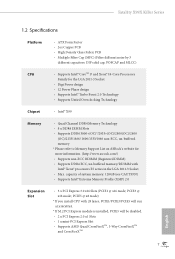
PCIE5 @ x8 mode) * If you install CPU with Intel® Xeon® processors E5 series in the LGA 2011-3 Socket • Max. capacity of system memory: 128GB (see CAUTION) • Supports Intel® Extreme Memory Proile (XMP) 2.0 Expansion Slot • 3 x PCI Express 3.0 x16 Slots (PCIE1 @ x16 mode; Fatal1ty X99X Killer Series 1.2 Speciications Platform • ATX Form Factor • 2oz Copper PCB • High Density Glass Fabric PCB • Multiple Filter Cap (MFC...
PCIE5 @ x8 mode) * If you install CPU with Intel® Xeon® processors E5 series in the LGA 2011-3 Socket • Max. capacity of system memory: 128GB (see CAUTION) • Supports Intel® Extreme Memory Proile (XMP) 2.0 Expansion Slot • 3 x PCI Express 3.0 x16 Slots (PCIE1 @ x16 mode; Fatal1ty X99X Killer Series 1.2 Speciications Platform • ATX Form Factor • 2oz Copper PCB • High Density Glass Fabric PCB • Multiple Filter Cap (MFC...

Quick Installation Guide
Page 13
Fatal1ty X99X Killer Series • 2 x RJ-45 LAN Ports with LED (ACT/LINK LED and SPEED LED) • 1 x Clear CMOS Switch • HD Audio Jacks: Rear Speaker / Central / Bass / Line in / Front Speaker / Microphone Storage • 10 x SATA3 6.0 Gb/s Connectors, support RAID (RAID 0, RAID 1, RAID 5, RAID 10 and Intel Rapid Storage 13), NCQ, AHCI, Hot Plug and ASRock HDD Saver Technology (SSATA3_3 connector is shared with the eSATA port) (SSATA3_2 connector is shared with Ultra M.2 Socket) * RAID is supported on SATA3_0 ~ SATA3_5 ports only. • 1 x eSATA Connector, supports NCQ, AHCI ...
Fatal1ty X99X Killer Series • 2 x RJ-45 LAN Ports with LED (ACT/LINK LED and SPEED LED) • 1 x Clear CMOS Switch • HD Audio Jacks: Rear Speaker / Central / Bass / Line in / Front Speaker / Microphone Storage • 10 x SATA3 6.0 Gb/s Connectors, support RAID (RAID 0, RAID 1, RAID 5, RAID 10 and Intel Rapid Storage 13), NCQ, AHCI, Hot Plug and ASRock HDD Saver Technology (SSATA3_3 connector is shared with the eSATA port) (SSATA3_2 connector is shared with Ultra M.2 Socket) * RAID is supported on SATA3_0 ~ SATA3_5 ports only. • 1 x eSATA Connector, supports NCQ, AHCI ...

Quick Installation Guide
Page 28
To use a 4-pin ATX power supply, please plug it along Pin 1 and Pin 13. his motherboard provides an 8-pin ATX 12V power connector. To use a 20-pin ATX power supply, please plug it to this connector when more than three graphics cards are installed. Please connect a hunderbolt™ add-in card (AIC) to this connector to this connector via the GPIO cable. ATX Power Connector (24-pin ATXPWR1) (see p.1, No. 9) ATX 12V Power Connector (8-pin ATX12V1) (see p.1, No. 3) PCIe Power Connector (4-pin PCIE_PWR1) (see p.1, No. 34) HDD Saver Connector (4-pin SATA_PWR_1) (see p.1, ...
To use a 4-pin ATX power supply, please plug it along Pin 1 and Pin 13. his motherboard provides an 8-pin ATX 12V power connector. To use a 20-pin ATX power supply, please plug it to this connector when more than three graphics cards are installed. Please connect a hunderbolt™ add-in card (AIC) to this connector to this connector via the GPIO cable. ATX Power Connector (24-pin ATXPWR1) (see p.1, No. 9) ATX 12V Power Connector (8-pin ATX12V1) (see p.1, No. 3) PCIe Power Connector (4-pin PCIE_PWR1) (see p.1, No. 34) HDD Saver Connector (4-pin SATA_PWR_1) (see p.1, ...
Quick Installation Guide
Page 31
Please clear CMOS, re-install the memory and VGA card, and remove other slots. Please press reset or clear CMOS. 92 - 99 Problem related to IDE or SATA devices. English 27 Code Description 00 Please check if the CPU is used to provide code information, which makes troubleshooting even easier. If the problem still exists, please clear CMOS and try removing all PCI-E devices or try using other memory modules. 61 - 91 Chipset initialization error. Fatal1ty X99X Killer Series 2.8 Dr. Debug Dr. Debug is installed correctly...
Please clear CMOS, re-install the memory and VGA card, and remove other slots. Please press reset or clear CMOS. 92 - 99 Problem related to IDE or SATA devices. English 27 Code Description 00 Please check if the CPU is used to provide code information, which makes troubleshooting even easier. If the problem still exists, please clear CMOS and try removing all PCI-E devices or try using other memory modules. 61 - 91 Chipset initialization error. Fatal1ty X99X Killer Series 2.8 Dr. Debug Dr. Debug is installed correctly...
RAID Installation Guide
Page 7
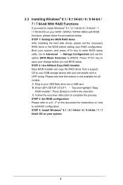
.... 2.3 Installing Windows® 8.1 / 8.1 64-bit / 8 / 8 64-bit / 7 / 7 64-bit With RAID Functions If you exit BIOS setup. STEP 1: Setting the BIOS RAID Items After installing the hard disk drives, please set the necessary RAID items in your USB storage device with RAID functions, please follow the procedures below. Go to Advanced Storage Coniguration and set RAID coniguration. STEP 2: Use ASRock Easy RAID Installer Easy RAID Installer can copy the RAID driver from a support CD to [RAID]. Press [Enter] to set the option SATA Mode Selection to your USB lash drive into a USB port...
.... 2.3 Installing Windows® 8.1 / 8.1 64-bit / 8 / 8 64-bit / 7 / 7 64-bit With RAID Functions If you exit BIOS setup. STEP 1: Setting the BIOS RAID Items After installing the hard disk drives, please set the necessary RAID items in your USB storage device with RAID functions, please follow the procedures below. Go to Advanced Storage Coniguration and set RAID coniguration. STEP 2: Use ASRock Easy RAID Installer Easy RAID Installer can copy the RAID driver from a support CD to [RAID]. Press [Enter] to set the option SATA Mode Selection to your USB lash drive into a USB port...


