User Manual
Page 9
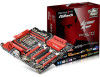
... latest VGA cards and CPU support list on ASRock's website without notice. ASRock website http://www.asrock.com. 1.1 Package Contents • ASRock Fatal1ty X99 Professional Series Motherboard (EATX Form Factor) • ASRock Fatal1ty X99 Professional Series Quick Installation Guide • ASRock Fatal1ty X99 Professional Series Support CD • 1 x I/O Panel Shield • 2 x ASRock SLI_Bridge Cards • 1 x ASRock SLI_Bridge_3S Card • 1 x ASRock 3-Way SLI Bridge Card • 6 x Serial ATA (SATA...
... latest VGA cards and CPU support list on ASRock's website without notice. ASRock website http://www.asrock.com. 1.1 Package Contents • ASRock Fatal1ty X99 Professional Series Motherboard (EATX Form Factor) • ASRock Fatal1ty X99 Professional Series Quick Installation Guide • ASRock Fatal1ty X99 Professional Series Support CD • 1 x I/O Panel Shield • 2 x ASRock SLI_Bridge Cards • 1 x ASRock SLI_Bridge_3S Card • 1 x ASRock 3-Way SLI Bridge Card • 6 x Serial ATA (SATA...

User Manual
Page 11
Fatal1ty X99 Professional Series • Supports AMD Quad CrossFireXTM, 4-Way CrossFireXTM, 3-Way CrossFireXTM and CrossFireXTM • Supports NVIDIA® Quad SLITM, 4-Way SLITM, 3-Way SLITM and SLITM * If you install CPU with Content Protection (Realtek ALC1150 Audio Codec) • Premium Blu-ray Audio support • Supports Surge Protection (ASRock Full Spike Protection) • Supports Purity...
Fatal1ty X99 Professional Series • Supports AMD Quad CrossFireXTM, 4-Way CrossFireXTM, 3-Way CrossFireXTM and CrossFireXTM • Supports NVIDIA® Quad SLITM, 4-Way SLITM, 3-Way SLITM and SLITM * If you install CPU with Content Protection (Realtek ALC1150 Audio Codec) • Premium Blu-ray Audio support • Supports Surge Protection (ASRock Full Spike Protection) • Supports Purity...

User Manual
Page 13
Fatal1ty X99 Professional Series BIOS Feature Hardware Monitor OS Certifications • 1 x Vertical Type A USB 3.0 • 2 x USB 3.0 Headers (Support 4 USB 3.0 ports) (ASMedia ASM1074 hub) (Supports ESD Protection (ASRock Full Spike Protection)) • 1 x Dr. Debug with LED • 1 x Power Switch with LED • 1 x Reset Switch with multilingual GUI support (1 x Main BIOS and 1 x Backup BIOS) &#...
Fatal1ty X99 Professional Series BIOS Feature Hardware Monitor OS Certifications • 1 x Vertical Type A USB 3.0 • 2 x USB 3.0 Headers (Support 4 USB 3.0 ports) (ASMedia ASM1074 hub) (Supports ESD Protection (ASRock Full Spike Protection)) • 1 x Dr. Debug with LED • 1 x Power Switch with LED • 1 x Reset Switch with multilingual GUI support (1 x Main BIOS and 1 x Backup BIOS) &#...

User Manual
Page 15
Fatal1ty X99 Professional Series 1.3 Motherboard Layout 12 3 4 5 67 8 USB 2.0 T: USB1 B: USB2 PS2 Keyboard /Mouse DDR4_D2 (64 bit, 284-pin module) DDR4_D1 (64 bit, 284-pin module) DDR4_C2 (64 ... CHA_FAN3 19 20 21 22 S_SATA3_0_1 M2_1 S_SATA3_2_3 CT5 CT4 RoHS CT3 CT2 CT1 23 MINI_PCIE1 Purity SoundTM 2 CT5 HD_AUDIO1 1 T BT1 1 SATA3_0_1 PCIE2 PCIE3 X99 Professional PCIE4 Intel X99 SATA3_2_3 SATA3_4_5 Ultra M.2 PCIe Gen3 x4 ULTRA_M2 CT4 PCIE_PWR1 CT3 CT2 Super I/O PCIE5 COM1 1 CHA_FAN1 USB5_6 USB3_4 CLRMOS1 1 1 1 1 Super I/O TPMS1 BIOS_A 128Mb BIOS ...
Fatal1ty X99 Professional Series 1.3 Motherboard Layout 12 3 4 5 67 8 USB 2.0 T: USB1 B: USB2 PS2 Keyboard /Mouse DDR4_D2 (64 bit, 284-pin module) DDR4_D1 (64 bit, 284-pin module) DDR4_C2 (64 ... CHA_FAN3 19 20 21 22 S_SATA3_0_1 M2_1 S_SATA3_2_3 CT5 CT4 RoHS CT3 CT2 CT1 23 MINI_PCIE1 Purity SoundTM 2 CT5 HD_AUDIO1 1 T BT1 1 SATA3_0_1 PCIE2 PCIE3 X99 Professional PCIE4 Intel X99 SATA3_2_3 SATA3_4_5 Ultra M.2 PCIe Gen3 x4 ULTRA_M2 CT4 PCIE_PWR1 CT3 CT2 Super I/O PCIE5 COM1 1 CHA_FAN1 USB5_6 USB3_4 CLRMOS1 1 1 1 1 Super I/O TPMS1 BIOS_A 128Mb BIOS ...

User Manual
Page 17
No. Description 34 Reset Switch (RST) 35 Chassis Fan Connector (CHA_FAN2) 36 TPM Header (TPMS1) 37 USB 2.0 Header (USB3_4) 38 USB 2.0 Header (USB5_6) 39 Chassis Fan Connector (CHA_FAN1) 40 Clear CMOS Jumper (CLRCMOS1) 41 COM Port Header (COM1) 42 PCIe Power Connector (PCIE_PWR1) 43 Thunderbolt AIC Connector (TB1) 44 Front Panel Audio Header (HD_AUDIO1) 45 Power Fan Connector (PWR_FAN1) Fatal1ty X99 Professional Series English 9
No. Description 34 Reset Switch (RST) 35 Chassis Fan Connector (CHA_FAN2) 36 TPM Header (TPMS1) 37 USB 2.0 Header (USB3_4) 38 USB 2.0 Header (USB5_6) 39 Chassis Fan Connector (CHA_FAN1) 40 Clear CMOS Jumper (CLRCMOS1) 41 COM Port Header (COM1) 42 PCIe Power Connector (PCIE_PWR1) 43 Thunderbolt AIC Connector (TB1) 44 Front Panel Audio Header (HD_AUDIO1) 45 Power Fan Connector (PWR_FAN1) Fatal1ty X99 Professional Series English 9

User Manual
Page 19
... LED indications. After restarting your computer, you are two LEDs on your system. Please select "Mixer ToolBox" , click "Enable playback multi-streaming", and click "ok". Fatal1ty X99 Professional Series * There are allowed to select "Realtek HDA Primary output" to use .
... LED indications. After restarting your computer, you are two LEDs on your system. Please select "Mixer ToolBox" , click "Enable playback multi-streaming", and click "ok". Fatal1ty X99 Professional Series * There are allowed to select "Realtek HDA Primary output" to use .

User Manual
Page 21
... there are any bent pins in the socket. Otherwise, the CPU will be seriously damaged. 2. CAUTION: Please note that X99 platform is only compatible with the LGA 2011-3 socket, which is found. Fatal1ty X99 Professional Series 2.1 Installing the CPU 1. Before you insert the 2011-3-Pin CPU into the socket if above situation is incompatible...
... there are any bent pins in the socket. Otherwise, the CPU will be seriously damaged. 2. CAUTION: Please note that X99 platform is only compatible with the LGA 2011-3 socket, which is found. Fatal1ty X99 Professional Series 2.1 Installing the CPU 1. Before you insert the 2011-3-Pin CPU into the socket if above situation is incompatible...

User Manual
Page 23
The cover must be placed if you wish to return the motherboard for after service. 15 English Fatal1ty X99 Professional Series 6 A B 7 A B 8 Please save and replace the cover if the processor is removed.
The cover must be placed if you wish to return the motherboard for after service. 15 English Fatal1ty X99 Professional Series 6 A B 7 A B 8 Please save and replace the cover if the processor is removed.

User Manual
Page 25
Fatal1ty X99 Professional Series 2.3 Installation of Memory Modules (DIMM) This motherboard provides eight 284-pin DDR4 (Double Data Rate 4) DIMM slots, and supports Quad Channel Memory Technology. 1. The ...
Fatal1ty X99 Professional Series 2.3 Installation of Memory Modules (DIMM) This motherboard provides eight 284-pin DDR4 (Double Data Rate 4) DIMM slots, and supports Quad Channel Memory Technology. 1. The ...

User Manual
Page 27
... CrossFireXTM or SLITM Mode x16 N/A N/A x16 N/A Three Graphics Cards in 3-Way CrossFireXTM Mode x8 or 3-Way SLITM Mode x8 N/A x16 N/A Four Graphics Cards in card. Fatal1ty X99 Professional Series 2.4 Expansion Slots (PCI Express Slots) There are 5 PCI Express slots and 1 mini-PCI Express slot on the motherboard. mini-PCIe slots: MINI_PCIE1 (mini-PCIe...
... CrossFireXTM or SLITM Mode x16 N/A N/A x16 N/A Three Graphics Cards in 3-Way CrossFireXTM Mode x8 or 3-Way SLITM Mode x8 N/A x16 N/A Four Graphics Cards in card. Fatal1ty X99 Professional Series 2.4 Expansion Slots (PCI Express Slots) There are 5 PCI Express slots and 1 mini-PCI Express slot on the motherboard. mini-PCIe slots: MINI_PCIE1 (mini-PCIe...

User Manual
Page 29
Fatal1ty X99 Professional Series 2.5 Jumpers Setup The illustration shows how jumpers are "Short" when a jumper cap is placed on these 2 pins. Clear CMOS Jumper (CLRCMOS1) (see p.7, No. 40) ...
Fatal1ty X99 Professional Series 2.5 Jumpers Setup The illustration shows how jumpers are "Short" when a jumper cap is placed on these 2 pins. Clear CMOS Jumper (CLRCMOS1) (see p.7, No. 40) ...

User Manual
Page 31
English 23 Fatal1ty X99 Professional Series Serial ATA3 Connectors (S_SATA3_0_1: see p.7, No. 22) (S_SATA3_2_3: see p.7, No. 23) (SATA3_0_1: see p.7, No. 24) (SATA3_2_3: see p.7, No. 25) (SATA3_4_5: see p.7, No. 26) SATA3_4 ...
English 23 Fatal1ty X99 Professional Series Serial ATA3 Connectors (S_SATA3_0_1: see p.7, No. 22) (S_SATA3_2_3: see p.7, No. 23) (SATA3_0_1: see p.7, No. 24) (SATA3_2_3: see p.7, No. 25) (SATA3_4_5: see p.7, No. 26) SATA3_4 ...

User Manual
Page 33
... provides an 8-pin ATX 12V power connector and a 4-pin ATX 12V power connector. To use a 4-pin ATX power supply, please plug it to the motherboard. Fatal1ty X99 Professional Series CPU Fan Connectors (4-pin CPU_FAN1) (see p.7, No. 5) (3-pin CPU_FAN2) (see p.7, No. 27) GND +12V DETECT 1 This motherboard provides a 24-pin ATX power connector. ATX...
... provides an 8-pin ATX 12V power connector and a 4-pin ATX 12V power connector. To use a 4-pin ATX power supply, please plug it to the motherboard. Fatal1ty X99 Professional Series CPU Fan Connectors (4-pin CPU_FAN1) (see p.7, No. 5) (3-pin CPU_FAN2) (see p.7, No. 27) GND +12V DETECT 1 This motherboard provides a 24-pin ATX power connector. ATX...

User Manual
Page 35
PIN1: 1.5V PCH: PCH PLL Voltage PIN2: 1.05V PCH: PCH Voltage PIN3: 1.05V CPU: CPU I .5V PCH 1.05V PCH 1.05V CPU VCCM CORE3 VCC_IN GND Users are able to measure onboard components voltage. V-ProbeTM (7-pin VOL_ CON1) (see p.7, No. 15) Fatal1ty X99 Professional Series 1 I /O Voltage (CPU_ V10) PIN4: VCCM: DRAM Voltage PIN5: CORE3: 3rd CPU CORE voltage (only works with 8-cores CPU) PIN6: VCC_IN: CPU Input Voltage PIN7: GND English 27
PIN1: 1.5V PCH: PCH PLL Voltage PIN2: 1.05V PCH: PCH Voltage PIN3: 1.05V CPU: CPU I .5V PCH 1.05V PCH 1.05V CPU VCCM CORE3 VCC_IN GND Users are able to measure onboard components voltage. V-ProbeTM (7-pin VOL_ CON1) (see p.7, No. 15) Fatal1ty X99 Professional Series 1 I /O Voltage (CPU_ V10) PIN4: VCCM: DRAM Voltage PIN5: CORE3: 3rd CPU CORE voltage (only works with 8-cores CPU) PIN6: VCC_IN: CPU Input Voltage PIN7: GND English 27

User Manual
Page 37
... for debug only. If you do not want to boot from the motherboard. However, if the primary BIOS is on the primary BIOS. English 29 Fatal1ty X99 Professional Series PCIe ON/OFF Switch (PCIE_SWITCH) (see p.7, No. 12) 1234 1: PCIE1 2: PCIE2 3: PCIE4 4: PCIE5 ON PCIe ON/OFF Switch allows you to find out the...
... for debug only. If you do not want to boot from the motherboard. However, if the primary BIOS is on the primary BIOS. English 29 Fatal1ty X99 Professional Series PCIe ON/OFF Switch (PCIE_SWITCH) (see p.7, No. 12) 1234 1: PCIE1 2: PCIE2 3: PCIE4 4: PCIE5 ON PCIe ON/OFF Switch allows you to find out the...
User Manual
Page 39
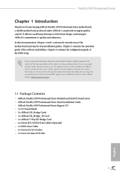
Please re-install the CPU and memory then clear CMOS. Please re-install the memory and CPU. English 31 Fatal1ty X99 Professional Series 2.8 Dr. Debug Dr. Debug is installed correctly and then clear CMOS. 0d Problem related to memory, VGA card or other devices. Please clear CMOS, ...
Please re-install the CPU and memory then clear CMOS. Please re-install the memory and CPU. English 31 Fatal1ty X99 Professional Series 2.8 Dr. Debug Dr. Debug is installed correctly and then clear CMOS. 0d Problem related to memory, VGA card or other devices. Please clear CMOS, ...

User Manual
Page 41
The lights go off if the four mentioned above are functioning normally. 33 English It emits a red light to indicate whether the CPU, memory, VGA or storage is dysfunctional. Fatal1ty X99 Professional Series 2.9 Post Status Checker Post Status Checker (PSC) diagnoses the computer when users power on the machine.
The lights go off if the four mentioned above are functioning normally. 33 English It emits a red light to indicate whether the CPU, memory, VGA or storage is dysfunctional. Fatal1ty X99 Professional Series 2.9 Post Status Checker Post Status Checker (PSC) diagnoses the computer when users power on the machine.
User Manual
Page 43
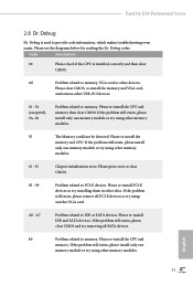
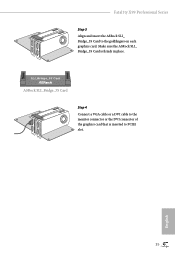
Make sure the ASRock SLI_ Bridge_3S Card is inserted to the goldfingers on each graphics card. Fatal1ty X99 Professional Series Step 3 Align and insert the ASRock SLI_ Bridge_3S Card to PCIE1 slot. 35 English SLI_Bridge_3S Card ASRock SLI_Bridge_3S Card Step 4 Connect a VGA cable or a DVI cable to the monitor connector or the DVI connector of the graphics card that is firmly in place.
Make sure the ASRock SLI_ Bridge_3S Card is inserted to the goldfingers on each graphics card. Fatal1ty X99 Professional Series Step 3 Align and insert the ASRock SLI_ Bridge_3S Card to PCIE1 slot. 35 English SLI_Bridge_3S Card ASRock SLI_Bridge_3S Card Step 4 Connect a VGA cable or a DVI cable to the monitor connector or the DVI connector of the graphics card that is firmly in place.

User Manual
Page 45
Fatal1ty X99 Professional Series Step 4 Connect a VGA cable or a DVI cable to the monitor connector or the DVI connector of the graphics card that is inserted to PCIE1 slot. 37 English
Fatal1ty X99 Professional Series Step 4 Connect a VGA cable or a DVI cable to the monitor connector or the DVI connector of the graphics card that is inserted to PCIE1 slot. 37 English

User Manual
Page 47
Fatal1ty X99 Professional Series Step 4 Connect a VGA cable or a DVI cable to the monitor connector or the DVI connector of the graphics card that is inserted to PCIE1 slot. 39 English
Fatal1ty X99 Professional Series Step 4 Connect a VGA cable or a DVI cable to the monitor connector or the DVI connector of the graphics card that is inserted to PCIE1 slot. 39 English