Intel Rapid Storage Guide
Page 13
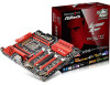
.... Select your controller from the list of Windows setup (during operating system setup: 1. At the prompt press Y to Specify Additional Device. 3. Press Enter to install the Intel Rapid Storage Technology driver during text-mode phase). 7. Install the RAID Driver Using the F6 Installation Method Perform the following files: IAAHCI.INF, IAAHCI.CAT, IASTOR.INF, IASTOR.CAT, IASTOR.SYS, and TXTSETUP.OEM. Use the Floppy Configuration Utility to create a floppy disk with a screen asking you see...
.... Select your controller from the list of Windows setup (during operating system setup: 1. At the prompt press Y to Specify Additional Device. 3. Press Enter to install the Intel Rapid Storage Technology driver during text-mode phase). 7. Install the RAID Driver Using the F6 Installation Method Perform the following files: IAAHCI.INF, IAAHCI.CAT, IASTOR.INF, IASTOR.CAT, IASTOR.SYS, and TXTSETUP.OEM. Use the Floppy Configuration Utility to create a floppy disk with a screen asking you see...
RAID Installation Guide
Page 7
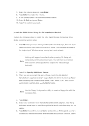
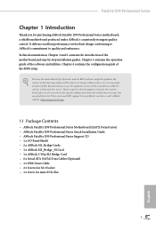
... change before setting your USB flash drive into a USB port B. Plug in your RAID configuration. STEP 2: Use ASRock Easy RAID Installer Easy RAID Installer can copy the RAID driver from a support CD to complete the process. Please note that this document for all models A. STEP 4: Install Windows® 8.1 / 8.1 64-bit / 8 / 8 64-bit / 7 / 7 64-bit OS on how to confirm the selection C. Enter UEFI SETUP UTILITY Tool and highlight "Easy RAID Installer". Follow the onscreen instruction to your system, and press key to [RAID]. Press [Enter...
... change before setting your USB flash drive into a USB port B. Plug in your RAID configuration. STEP 2: Use ASRock Easy RAID Installer Easy RAID Installer can copy the RAID driver from a support CD to complete the process. Please note that this document for all models A. STEP 4: Install Windows® 8.1 / 8.1 64-bit / 8 / 8 64-bit / 7 / 7 64-bit OS on how to confirm the selection C. Enter UEFI SETUP UTILITY Tool and highlight "Easy RAID Installer". Follow the onscreen instruction to your system, and press key to [RAID]. Press [Enter...
User Manual
Page 9
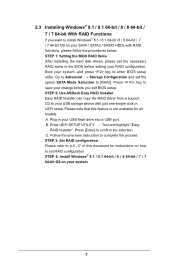
...If you are using. ASRock website http://www.asrock.com. 1.1 Package Contents • ASRock Fatal1ty X99 Professional Series Motherboard (EATX Form Factor) • ASRock Fatal1ty X99 Professional Series Quick Installation Guide • ASRock Fatal1ty X99 Professional Series Support CD • 1 x I/O Panel Shield • 2 x ASRock SLI_Bridge Cards • 1 x ASRock SLI_Bridge_3S Card • 1 x ASRock 3-Way SLI Bridge Card • 6 x Serial ATA (SATA) Data Cables (Optional) • 1 x HDD Saver Cable • 2 x Screws for M.2 Socket • 1 x Screw for mini-PCIe Slot 1 English It...
...If you are using. ASRock website http://www.asrock.com. 1.1 Package Contents • ASRock Fatal1ty X99 Professional Series Motherboard (EATX Form Factor) • ASRock Fatal1ty X99 Professional Series Quick Installation Guide • ASRock Fatal1ty X99 Professional Series Support CD • 1 x I/O Panel Shield • 2 x ASRock SLI_Bridge Cards • 1 x ASRock SLI_Bridge_3S Card • 1 x ASRock 3-Way SLI Bridge Card • 6 x Serial ATA (SATA) Data Cables (Optional) • 1 x HDD Saver Cable • 2 x Screws for M.2 Socket • 1 x Screw for mini-PCIe Slot 1 English It...

User Manual
Page 12
...; 2 x USB 3.0 Ports (Supports ESD Protection (ASRock Full Spike Protection)) • 2 x RJ-45 LAN Ports with LED (ACT/LINK LED and SPEED LED) • 1 x Clear CMOS Switch • HD Audio Jacks: Rear Speaker / Central / Bass / Line in / Front Speaker / Microphone Storage • 10 x SATA3 6.0 Gb/s Connectors, support RAID (RAID 0, RAID 1, RAID 5, RAID 10 and Intel Rapid Storage 13), NCQ, AHCI, Hot Plug and ASRock HDD Saver Technology (S_SATA3_3 connector is shared with M.2 Socket (M2_1)) * RAID is supported on SATA3_0 ~ SATA3_5 ports only. • 1 x Ultra M.2 Socket (ULTRA_M2), supports...
...; 2 x USB 3.0 Ports (Supports ESD Protection (ASRock Full Spike Protection)) • 2 x RJ-45 LAN Ports with LED (ACT/LINK LED and SPEED LED) • 1 x Clear CMOS Switch • HD Audio Jacks: Rear Speaker / Central / Bass / Line in / Front Speaker / Microphone Storage • 10 x SATA3 6.0 Gb/s Connectors, support RAID (RAID 0, RAID 1, RAID 5, RAID 10 and Intel Rapid Storage 13), NCQ, AHCI, Hot Plug and ASRock HDD Saver Technology (S_SATA3_3 connector is shared with M.2 Socket (M2_1)) * RAID is supported on SATA3_0 ~ SATA3_5 ports only. • 1 x Ultra M.2 Socket (ULTRA_M2), supports...

User Manual
Page 13
... to adjust OC frequency • 1 x Menu Button • 1 x PCIe ON/OFF Switch • 1 x Slow Mode Switch • 1 x LN2 Mode Switch • 1 x BIOS Selection Switch • 1 x Direct Key Button • 2 x 128Mb AMI UEFI Legal BIOS with LED • V-ProbeTM: 7-set of onboard voltage measurement points laid • Rapid OC Buttons: +/- Fatal1ty X99 Professional Series BIOS Feature Hardware Monitor OS Certifications • 1 x Vertical Type A USB 3.0 • 2 x USB 3.0 Headers (Support 4 USB 3.0 ports) (ASMedia ASM1074 hub) (Supports ESD Protection (ASRock Full Spike Protection...
... to adjust OC frequency • 1 x Menu Button • 1 x PCIe ON/OFF Switch • 1 x Slow Mode Switch • 1 x LN2 Mode Switch • 1 x BIOS Selection Switch • 1 x Direct Key Button • 2 x 128Mb AMI UEFI Legal BIOS with LED • V-ProbeTM: 7-set of onboard voltage measurement points laid • Rapid OC Buttons: +/- Fatal1ty X99 Professional Series BIOS Feature Hardware Monitor OS Certifications • 1 x Vertical Type A USB 3.0 • 2 x USB 3.0 Headers (Support 4 USB 3.0 ports) (ASMedia ASM1074 hub) (Supports ESD Protection (ASRock Full Spike Protection...

User Manual
Page 16
...Slow Mode Switch (SLOWMODE) 15 V-ProbeTM (VOL_CON1) 16 Post Status Checker (PSC) 17 ATX Power Connector (ATXPWR1) 18 USB 3.0 Header (USB3_7_8) 19 Vertical Type A USB 3.0 (USB3_8) 20 Chassis Fan Connector (CHA_FAN3) 21 USB 3.0 Header (USB3_9_10) 22 SATA3 Connectors (S_SATA3_0_1) 23 SATA3 Connectors (S_SATA3_2_3) 24 SATA3 Connectors (SATA3_0_1) 25 SATA3 Connectors (SATA3_2_3) 26 SATA3 Connectors (SATA3_4_5) 27 HDD Saver Connector (SATA_PWR_1) 28 BIOS Selection Switch (BIOS_SEL1) 29 Power LED Header (PLED1) 30 Direct Key Button (DIRKEY1) 31 Chassis Speaker Header (SPEAKER1) 32 System Panel Header...
...Slow Mode Switch (SLOWMODE) 15 V-ProbeTM (VOL_CON1) 16 Post Status Checker (PSC) 17 ATX Power Connector (ATXPWR1) 18 USB 3.0 Header (USB3_7_8) 19 Vertical Type A USB 3.0 (USB3_8) 20 Chassis Fan Connector (CHA_FAN3) 21 USB 3.0 Header (USB3_9_10) 22 SATA3 Connectors (S_SATA3_0_1) 23 SATA3 Connectors (S_SATA3_2_3) 24 SATA3 Connectors (SATA3_0_1) 25 SATA3 Connectors (SATA3_2_3) 26 SATA3 Connectors (SATA3_4_5) 27 HDD Saver Connector (SATA_PWR_1) 28 BIOS Selection Switch (BIOS_SEL1) 29 Power LED Header (PLED1) 30 Direct Key Button (DIRKEY1) 31 Chassis Speaker Header (SPEAKER1) 32 System Panel Header...

User Manual
Page 33
...p.7, No. 4) PCIe Power Connector (4-pin PCIE_PWR1) (see p.7, No. 42) HDD Saver Connector (4-pin SATA_PWR_1) (see p.7, No. 8) +12V CPU_FAN_SPEED GND FAN_SPEED_CONTROL GND FAN_VOLTAGE CPU_FAN_SPEED This motherboard provides a 4-Pin CPU fan (Quiet Fan) connector. Please connect the HDD Saver Cable to Pin 1-3. To use a 4-pin ATX power supply, please plug it to this connector when more than three graphics cards are installed. If you plan to connect a 3-Pin CPU fan, please connect it along Pin 1 and Pin 13. Fatal1ty X99 Professional Series CPU Fan Connectors (4-pin CPU_FAN1) (see...
...p.7, No. 4) PCIe Power Connector (4-pin PCIE_PWR1) (see p.7, No. 42) HDD Saver Connector (4-pin SATA_PWR_1) (see p.7, No. 8) +12V CPU_FAN_SPEED GND FAN_SPEED_CONTROL GND FAN_VOLTAGE CPU_FAN_SPEED This motherboard provides a 4-Pin CPU fan (Quiet Fan) connector. Please connect the HDD Saver Cable to Pin 1-3. To use a 4-pin ATX power supply, please plug it to this connector when more than three graphics cards are installed. If you plan to connect a 3-Pin CPU fan, please connect it along Pin 1 and Pin 13. Fatal1ty X99 Professional Series CPU Fan Connectors (4-pin CPU_FAN1) (see...
User Manual
Page 39
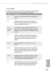
... Problem related to PCI-E devices. Please re-install the memory and CPU. If the problem still exists, please clear CMOS and try using another VGA card. Please press reset or clear CMOS. 92 - 99 Problem related to memory. A7 Problem related to memory. Fatal1ty X99 Professional Series 2.8 Dr. Debug Dr. Debug is installed correctly and then clear CMOS. 0d Problem related to memory, VGA card or other devices. Please re-install the CPU and memory then clear CMOS. A0 - b0 Problem related to IDE or SATA devices. Please re-install the CPU...
... Problem related to PCI-E devices. Please re-install the memory and CPU. If the problem still exists, please clear CMOS and try using another VGA card. Please press reset or clear CMOS. 92 - 99 Problem related to memory. A7 Problem related to memory. Fatal1ty X99 Professional Series 2.8 Dr. Debug Dr. Debug is installed correctly and then clear CMOS. 0d Problem related to memory, VGA card or other devices. Please re-install the CPU and memory then clear CMOS. A0 - b0 Problem related to IDE or SATA devices. Please re-install the CPU...

User Manual
Page 49
... minimum power your graphics card driver supports AMD CrossFireXTM technology. If you purchase, not bundled with a 16-pipe card, both cards will operate as 12-pipe cards while in CrossFireXTM mode. 5. Different CrossFireXTM cards may require different methods to PCIE4 slot. Fatal1ty X99 Professional Series 2.11 CrossFireXTM, 3-Way CrossFireXTM , 4-Way CrossFireXTM and Quad CrossFireXTM Operation Guide This motherboard supports CrossFireXTM, 3-way CrossFireXTM, 4-way CrossFireXTM and Quad CrossFireXTM that allows you install CPU...
... minimum power your graphics card driver supports AMD CrossFireXTM technology. If you purchase, not bundled with a 16-pipe card, both cards will operate as 12-pipe cards while in CrossFireXTM mode. 5. Different CrossFireXTM cards may require different methods to PCIE4 slot. Fatal1ty X99 Professional Series 2.11 CrossFireXTM, 3-Way CrossFireXTM , 4-Way CrossFireXTM and Quad CrossFireXTM Operation Guide This motherboard supports CrossFireXTM, 3-way CrossFireXTM, 4-way CrossFireXTM and Quad CrossFireXTM that allows you install CPU...
User Manual
Page 52
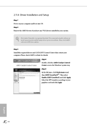
... installed Catalyst drivers prior to installation. Step 3 Install the required drivers and CATALYST Control Center then restart your system. Select the GPU number according to uninstall any VGA drivers installed in the Windows® system tray. We recommend using this utility to your computer and boot into OS. Please check AMD's website for details. The Catalyst Uninstaller is an optional download. 2.11.4 Driver Installation and Setup Step 1 Power on your graphics card...
... installed Catalyst drivers prior to installation. Step 3 Install the required drivers and CATALYST Control Center then restart your system. Select the GPU number according to uninstall any VGA drivers installed in the Windows® system tray. We recommend using this utility to your computer and boot into OS. Please check AMD's website for details. The Catalyst Uninstaller is an optional download. 2.11.4 Driver Installation and Setup Step 1 Power on your graphics card...
User Manual
Page 57
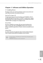
... CD-ROM drive. Therefore, the drivers you install can work properly. Drivers Menu The drivers compatible to display the menu. If the Main Menu does not appear automatically, locate and double click on a specific item then follow the order from top to bottom to install it. Click on the file "ASRSETUP.EXE" in your computer. Fatal1ty X99 Professional Series Chapter 3 Software and Utilities Operation 3.1 Installing Drivers The Support CD that comes with the motherboard contains necessary drivers and useful utilities...
... CD-ROM drive. Therefore, the drivers you install can work properly. Drivers Menu The drivers compatible to display the menu. If the Main Menu does not appear automatically, locate and double click on a specific item then follow the order from top to bottom to install it. Click on the file "ASRSETUP.EXE" in your computer. Fatal1ty X99 Professional Series Chapter 3 Software and Utilities Operation 3.1 Installing Drivers The Support CD that comes with the motherboard contains necessary drivers and useful utilities...
User Manual
Page 63
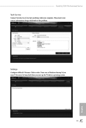
Please leave your contact information along with your computer. Settings Configure ASRock F-Stream. Click to select "Auto run at Windows Startup" if you want F-Stream to be launched when you have problems with details of the problem. Fatal1ty X99 Professional Series Tech Service Contact Tech Service if you start up the Windows operating system. 55 English
Please leave your contact information along with your computer. Settings Configure ASRock F-Stream. Click to select "Auto run at Windows Startup" if you want F-Stream to be launched when you have problems with details of the problem. Fatal1ty X99 Professional Series Tech Service Contact Tech Service if you start up the Windows operating system. 55 English

User Manual
Page 114
...English Legacy USB Support Enable or disable Legacy OS Support for USB 3.0 devices. Select UEFI Setup Only to use USB devices under the UEFI setup and Windows/Linux operating systems only. Set [Smart Auto] to keep the USB 3.0 driver enabled (Must install driver to support USB devices under Windows® 7). Legacy USB 3.0 Support Enable or disable Legacy OS Support for USB 2.0 devices. Select UEFI Setup Only to disable the USB 3.0 ports. 4.4.6 USB Configuration USB Controller Enable or disable all the USB ports. Intel USB 3.0 Mode Select Intel® USB 3.0 controller mode.
...English Legacy USB Support Enable or disable Legacy OS Support for USB 3.0 devices. Select UEFI Setup Only to use USB devices under the UEFI setup and Windows/Linux operating systems only. Set [Smart Auto] to keep the USB 3.0 driver enabled (Must install driver to support USB devices under Windows® 7). Legacy USB 3.0 Support Enable or disable Legacy OS Support for USB 2.0 devices. Select UEFI Setup Only to disable the USB 3.0 ports. 4.4.6 USB Configuration USB Controller Enable or disable all the USB ports. Intel USB 3.0 Mode Select Intel® USB 3.0 controller mode.
User Manual
Page 118
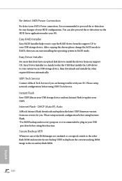
... Flash Save UEFI files in your OS. DHCP (Auto IP), Auto ASRock Internet Flash downloads and updates the latest UEFI firmware version from our support CD, Easy Driver Installer is a handy tool in RAID mode. Internet Flash - Re-detect SATA Power Connection Re-detect your USB storage device. Secure Backup UEFI Whenever one of your system via the HDD Saver application under your USB pen drive before using this function. You can start installing the operating system in the UEFI that installs the LAN driver...
... Flash Save UEFI files in your OS. DHCP (Auto IP), Auto ASRock Internet Flash downloads and updates the latest UEFI firmware version from our support CD, Easy Driver Installer is a handy tool in RAID mode. Internet Flash - Re-detect SATA Power Connection Re-detect your USB storage device. Secure Backup UEFI Whenever one of your system via the HDD Saver application under your USB pen drive before using this function. You can start installing the operating system in the UEFI that installs the LAN driver...

User Manual
Page 119
Load User Default Load previously saved user defaults. 111 English Save User Default Type a profile name and press enter to configure internet connection settings for Internet Flash. Fatal1ty X99 Professional Series Network Configuration Use this to save your settings as user default. UEFI Download Server Select a server to download the UEFI firmware. Internet Setting Enable or disable sound effects in the setup utility.
Load User Default Load previously saved user defaults. 111 English Save User Default Type a profile name and press enter to configure internet connection settings for Internet Flash. Fatal1ty X99 Professional Series Network Configuration Use this to save your settings as user default. UEFI Download Server Select a server to download the UEFI firmware. Internet Setting Enable or disable sound effects in the setup utility.

Quick Installation Guide
Page 6
...Slow Mode Switch (SLOWMODE) 15 V-ProbeTM (VOL_CON1) 16 Post Status Checker (PSC) 17 ATX Power Connector (ATXPWR1) 18 USB 3.0 Header (USB3_7_8) 19 Vertical Type A USB 3.0 (USB3_8) 20 Chassis Fan Connector (CHA_FAN3) 21 USB 3.0 Header (USB3_9_10) 22 SATA3 Connectors (S_SATA3_0_1) 23 SATA3 Connectors (S_SATA3_2_3) 24 SATA3 Connectors (SATA3_0_1) 25 SATA3 Connectors (SATA3_2_3) 26 SATA3 Connectors (SATA3_4_5) 27 HDD Saver Connector (SATA_PWR_1) 28 BIOS Selection Switch (BIOS_SEL1) 29 Power LED Header (PLED1) 30 Direct Key Button (DIRKEY1) 31 Chassis Speaker Header (SPEAKER1) 32 System Panel Header...
...Slow Mode Switch (SLOWMODE) 15 V-ProbeTM (VOL_CON1) 16 Post Status Checker (PSC) 17 ATX Power Connector (ATXPWR1) 18 USB 3.0 Header (USB3_7_8) 19 Vertical Type A USB 3.0 (USB3_8) 20 Chassis Fan Connector (CHA_FAN3) 21 USB 3.0 Header (USB3_9_10) 22 SATA3 Connectors (S_SATA3_0_1) 23 SATA3 Connectors (S_SATA3_2_3) 24 SATA3 Connectors (SATA3_0_1) 25 SATA3 Connectors (SATA3_2_3) 26 SATA3 Connectors (SATA3_4_5) 27 HDD Saver Connector (SATA_PWR_1) 28 BIOS Selection Switch (BIOS_SEL1) 29 Power LED Header (PLED1) 30 Direct Key Button (DIRKEY1) 31 Chassis Speaker Header (SPEAKER1) 32 System Panel Header...
Quick Installation Guide
Page 13
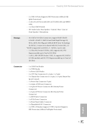
Fatal1ty X99 Professional Series • 2 x USB 3.0 Ports (Supports ESD Protection (ASRock Full Spike Protection)) • 2 x RJ-45 LAN Ports with LED (ACT/LINK LED and SPEED LED) • 1 x Clear CMOS Switch • HD Audio Jacks: Rear Speaker / Central / Bass / Line in / Front Speaker / Microphone Storage • 10 x SATA3 6.0 Gb/s Connectors, support RAID (RAID 0, RAID 1, RAID 5, RAID 10 and Intel Rapid Storage 13), NCQ, AHCI, Hot Plug and ASRock HDD Saver Technology (S_SATA3_3 connector is shared with M.2 Socket (M2_1)) * RAID is supported on SATA3_0 ~ SATA3_5 ports only. • 1...
Fatal1ty X99 Professional Series • 2 x USB 3.0 Ports (Supports ESD Protection (ASRock Full Spike Protection)) • 2 x RJ-45 LAN Ports with LED (ACT/LINK LED and SPEED LED) • 1 x Clear CMOS Switch • HD Audio Jacks: Rear Speaker / Central / Bass / Line in / Front Speaker / Microphone Storage • 10 x SATA3 6.0 Gb/s Connectors, support RAID (RAID 0, RAID 1, RAID 5, RAID 10 and Intel Rapid Storage 13), NCQ, AHCI, Hot Plug and ASRock HDD Saver Technology (S_SATA3_3 connector is shared with M.2 Socket (M2_1)) * RAID is supported on SATA3_0 ~ SATA3_5 ports only. • 1...

Quick Installation Guide
Page 29
...the HDD Saver Cable to this connector to this connector when more than three graphics cards are installed. If you plan to connect a 3-Pin CPU fan, please connect it to the motherboard. Fatal1ty X99 Professional Series CPU Fan Connectors (4-pin CPU_FAN1) (see p.1, No. 5) (3-pin CPU_FAN2) (see p.1, No. 27) GND +12V DETECT 1 This motherboard provides a 24-pin ATX power connector. To use a 4-pin ATX power supply, please plug it along Pin 1 and Pin 5. *The 4-pin ATX 12V power connector is used to supply additional power to Pin 1-3. To use a 20-pin ATX power supply, please plug it...
...the HDD Saver Cable to this connector to this connector when more than three graphics cards are installed. If you plan to connect a 3-Pin CPU fan, please connect it to the motherboard. Fatal1ty X99 Professional Series CPU Fan Connectors (4-pin CPU_FAN1) (see p.1, No. 5) (3-pin CPU_FAN2) (see p.1, No. 27) GND +12V DETECT 1 This motherboard provides a 24-pin ATX power connector. To use a 4-pin ATX power supply, please plug it along Pin 1 and Pin 5. *The 4-pin ATX 12V power connector is used to supply additional power to Pin 1-3. To use a 20-pin ATX power supply, please plug it...

Quick Installation Guide
Page 35
... memory and VGA card, and remove other devices. If the problem still exists, please remove all PCI-E devices or try removing all SATA devices. Please re-install the CPU and memory. A0 - Fatal1ty X99 Professional Series 2.8 Dr. Debug Dr. Debug is installed correctly and then clear CMOS. 0d Problem related to memory, VGA card or other USB, PCI devices. 01 - 54 (except 0d), 5A- 60 Problem related to memory. b0 Problem related to provide code information, which makes troubleshooting even easier. Please re-install IDE and SATA devices...
... memory and VGA card, and remove other devices. If the problem still exists, please remove all PCI-E devices or try removing all SATA devices. Please re-install the CPU and memory. A0 - Fatal1ty X99 Professional Series 2.8 Dr. Debug Dr. Debug is installed correctly and then clear CMOS. 0d Problem related to memory, VGA card or other USB, PCI devices. 01 - 54 (except 0d), 5A- 60 Problem related to memory. b0 Problem related to provide code information, which makes troubleshooting even easier. Please re-install IDE and SATA devices...

Quick Installation Guide
Page 41
Fatal1ty X99 Professional Series 2.11 HDD Saver Cable Installation Guide The HDD Saver Connector on this motherboard allows you to switch on the motherboard. Connect one end of the HDD Saver Cable to two SATA HDDs. 2. Please follow the steps below to the section 3.2 "F-Stream" in the user manual. 37 English Then connect the other end to your SATA HDD(s). * The HDD Saver Connector supports up to the HDD Saver Connector (SATA_ PWR_1) placed near the SATA ports. This design secures...
Fatal1ty X99 Professional Series 2.11 HDD Saver Cable Installation Guide The HDD Saver Connector on this motherboard allows you to switch on the motherboard. Connect one end of the HDD Saver Cable to two SATA HDDs. 2. Please follow the steps below to the section 3.2 "F-Stream" in the user manual. 37 English Then connect the other end to your SATA HDD(s). * The HDD Saver Connector supports up to the HDD Saver Connector (SATA_ PWR_1) placed near the SATA ports. This design secures...


