
Intel Rapid Storage Guide
Page 12
... the up or down arrow keys to select the strip size and press Enter. 5. Enable RAID in System BIOS Use the instructions included with your motherboard to enable RAID in the system BIOS, a RAID volume must be created, and the F6 installation method must be used to load the Intel®...
... the up or down arrow keys to select the strip size and press Enter. 5. Enable RAID in System BIOS Use the instructions included with your motherboard to enable RAID in the system BIOS, a RAID volume must be created, and the F6 installation method must be used to load the Intel®...
RAID Installation Guide
Page 2
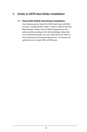
This section will guide you how to create RAID on this guide carefully according to SATA Hard Disks Installation 1.1 Serial ATA (SATA) Hard Disks Installation Intel chipset supports Serial ATA (SATA) hard disks with RAID functions, including RAID 0, RAID 1, RAID 5, RAID 10 and Intel Rapid Storage. Please read the RAID configurations in this motherboard for internal storage devices. You may install SATA hard disks on SATA ports. 2 Guide to the Intel southbridge chipset that your motherboard adopts. 1.
This section will guide you how to create RAID on this guide carefully according to SATA Hard Disks Installation 1.1 Serial ATA (SATA) Hard Disks Installation Intel chipset supports Serial ATA (SATA) hard disks with RAID functions, including RAID 0, RAID 1, RAID 5, RAID 10 and Intel Rapid Storage. Please read the RAID configurations in this motherboard for internal storage devices. You may install SATA hard disks on SATA ports. 2 Guide to the Intel southbridge chipset that your motherboard adopts. 1.
RAID Installation Guide
Page 3
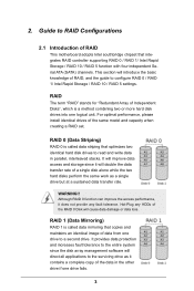
... tolerance to read and write data in the other drive if one logical unit. RAID The term "RAID" stands for "Redundant Array of RAID This motherboard adopts Intel southbridge chipset that optimizes two identical hard disk drives to the entire system since it will introduce the basic knowledge of the same...
... tolerance to read and write data in the other drive if one logical unit. RAID The term "RAID" stands for "Redundant Array of RAID This motherboard adopts Intel southbridge chipset that optimizes two identical hard disk drives to the entire system since it will introduce the basic knowledge of the same...
RAID Installation Guide
Page 18
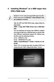
... than 2TB. STEP 1: Copy Intel® RAID drivers into a USB flash disk You can download the drivers from ASRock's website and unzip the files into a USB flash disk or copy the files from ASRock's motherboard support CD. (Please copy the files under the following directory: 32 bit: ..\i386\Win7_Intel.. 64-bit: ..\AMD64\Win7...
... than 2TB. STEP 1: Copy Intel® RAID drivers into a USB flash disk You can download the drivers from ASRock's website and unzip the files into a USB flash disk or copy the files from ASRock's motherboard support CD. (Please copy the files under the following directory: 32 bit: ..\i386\Win7_Intel.. 64-bit: ..\AMD64\Win7...
RAID Installation Guide
Page 20
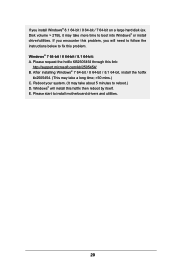
... this problem. Please request the hotfix KB2505454 through this hotfix then reboot by itself. Windows® will need to follow the instructions below to install motherboard drivers and utilities. 20 E. Disk volume > 2TB), it may take a long time; >30 mins.) C. Reboot your system. (It may take more time to reboot.) D. If...
... this problem. Please request the hotfix KB2505454 through this hotfix then reboot by itself. Windows® will need to follow the instructions below to install motherboard drivers and utilities. 20 E. Disk volume > 2TB), it may take a long time; >30 mins.) C. Reboot your system. (It may take more time to reboot.) D. If...

User Manual
Page 2
...or explanation and to infringe. This device complies with Part 15 of this motherboard contains Perchlorate, a toxic substance controlled in Perchlorate Best Management Practices (BMP) regulations passed by ASRock. "Perchlorate Material-special handling may be constructed as a commitment by the...USA ONLY The Lithium battery adopted on this documentation may apply, see www.dtsc.ca.gov/hazardouswaste/ perchlorate" ASRock Website: http://www.asrock.com Disclaimer: Specifications and information contained in advance. When you discard the Lithium battery in California, USA, ...
...or explanation and to infringe. This device complies with Part 15 of this motherboard contains Perchlorate, a toxic substance controlled in Perchlorate Best Management Practices (BMP) regulations passed by ASRock. "Perchlorate Material-special handling may be constructed as a commitment by the...USA ONLY The Lithium battery adopted on this documentation may apply, see www.dtsc.ca.gov/hazardouswaste/ perchlorate" ASRock Website: http://www.asrock.com Disclaimer: Specifications and information contained in advance. When you discard the Lithium battery in California, USA, ...

User Manual
Page 6
Contents Chapter 1 Introduction 1 1.1 Package Contents 1 1.2 Specifications 2 1.3 Motherboard Layout 7 1.4 I/O Panel 10 Chapter 2 Installation 12 2.1 Installing the CPU 13 2.2 Installing the CPU Fan and Heatsink 16 2.3 Installation of Memory Modules (DIMM) 17 2.4 Expansion Slots (...
Contents Chapter 1 Introduction 1 1.1 Package Contents 1 1.2 Specifications 2 1.3 Motherboard Layout 7 1.4 I/O Panel 10 Chapter 2 Installation 12 2.1 Installing the CPU 13 2.2 Installing the CPU Fan and Heatsink 16 2.3 Installation of Memory Modules (DIMM) 17 2.4 Expansion Slots (...
User Manual
Page 9
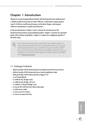
...; ASRock Fatal1ty X99 Professional Series Motherboard (EATX Form Factor) • ASRock Fatal1ty X99 Professional Series Quick Installation Guide • ASRock Fatal1ty X99 Professional Series Support CD • 1 x I/O Panel Shield • 2 x ASRock SLI_Bridge Cards • 1 x ASRock SLI_Bridge_3S Card • 1 x ASRock 3-Way SLI Bridge Card • 6 x Serial ATA (SATA) Data Cables (Optional) • 1 x HDD Saver Cable • 2 x Screws for M.2 Socket • 1 x Screw for purchasing ASRock Fatal1ty X99 Professional Series motherboard, a reliable motherboard produced under ASRock...
...; ASRock Fatal1ty X99 Professional Series Motherboard (EATX Form Factor) • ASRock Fatal1ty X99 Professional Series Quick Installation Guide • ASRock Fatal1ty X99 Professional Series Support CD • 1 x I/O Panel Shield • 2 x ASRock SLI_Bridge Cards • 1 x ASRock SLI_Bridge_3S Card • 1 x ASRock 3-Way SLI Bridge Card • 6 x Serial ATA (SATA) Data Cables (Optional) • 1 x HDD Saver Cable • 2 x Screws for M.2 Socket • 1 x Screw for purchasing ASRock Fatal1ty X99 Professional Series motherboard, a reliable motherboard produced under ASRock...

User Manual
Page 15
Fatal1ty X99 Professional Series 1.3 Motherboard Layout 12 3 4 5 67 8 USB 2.0 T: USB1 B: USB2 PS2 Keyboard /Mouse DDR4_D2 (64 bit, 284-pin module) DDR4_D1 (64 bit, 284-pin module) DDR4_C2 (64 bit, ... CHA_FAN3 19 20 21 22 S_SATA3_0_1 M2_1 S_SATA3_2_3 CT5 CT4 RoHS CT3 CT2 CT1 23 MINI_PCIE1 Purity SoundTM 2 CT5 HD_AUDIO1 1 T BT1 1 SATA3_0_1 PCIE2 PCIE3 X99 Professional PCIE4 Intel X99 SATA3_2_3 SATA3_4_5 Ultra M.2 PCIe Gen3 x4 ULTRA_M2 CT4 PCIE_PWR1 CT3 CT2 Super I/O PCIE5 COM1 1 CHA_FAN1 USB5_6 USB3_4 CLRMOS1 1 1 1 1 Super I/O TPMS1 BIOS_A 128Mb BIOS...
Fatal1ty X99 Professional Series 1.3 Motherboard Layout 12 3 4 5 67 8 USB 2.0 T: USB1 B: USB2 PS2 Keyboard /Mouse DDR4_D2 (64 bit, 284-pin module) DDR4_D1 (64 bit, 284-pin module) DDR4_C2 (64 bit, ... CHA_FAN3 19 20 21 22 S_SATA3_0_1 M2_1 S_SATA3_2_3 CT5 CT4 RoHS CT3 CT2 CT1 23 MINI_PCIE1 Purity SoundTM 2 CT5 HD_AUDIO1 1 T BT1 1 SATA3_0_1 PCIE2 PCIE3 X99 Professional PCIE4 Intel X99 SATA3_2_3 SATA3_4_5 Ultra M.2 PCIe Gen3 x4 ULTRA_M2 CT4 PCIE_PWR1 CT3 CT2 Super I/O PCIE5 COM1 1 CHA_FAN1 USB5_6 USB3_4 CLRMOS1 1 1 1 1 Super I/O TPMS1 BIOS_A 128Mb BIOS...

User Manual
Page 20
...the chassis, please do not overtighten the screws! Doing so may cause physical injuries and damages to motherboard components. • In order to avoid damage from static electricity to the motherboard's components, NEVER place your chassis to unplug the power cord before you handle the components. •... Hold components by the edges and do so may damage the motherboard. 12 English Before you uninstall any motherboard settings. • Make sure to ensure that comes with the components. • When placing screws to secure the...
...the chassis, please do not overtighten the screws! Doing so may cause physical injuries and damages to motherboard components. • In order to avoid damage from static electricity to the motherboard's components, NEVER place your chassis to unplug the power cord before you handle the components. •... Hold components by the edges and do so may damage the motherboard. 12 English Before you uninstall any motherboard settings. • Make sure to ensure that comes with the components. • When placing screws to secure the...

User Manual
Page 23
Fatal1ty X99 Professional Series 6 A B 7 A B 8 Please save and replace the cover if the processor is removed. The cover must be placed if you wish to return the motherboard for after service. 15 English
Fatal1ty X99 Professional Series 6 A B 7 A B 8 Please save and replace the cover if the processor is removed. The cover must be placed if you wish to return the motherboard for after service. 15 English

User Manual
Page 25
...more than four memory modules, please install the other memory modules from left to right (from DDR4_A2, DDR4_B2, DDR4_D2 to the motherboard and the DIMM if you always need to Intel® CPU spec definition, please install the memory modules on DDR4_A1, DDR4_B1... identical (the same brand, speed, size and chip-type) DDR4 DIMM pairs. 2. English 17 It is activated. Fatal1ty X99 Professional Series 2.3 Installation of Memory Modules (DIMM) This motherboard provides eight 284-pin DDR4 (Double Data Rate 4) DIMM slots, and supports Quad Channel Memory Technology. 1. If more...
...more than four memory modules, please install the other memory modules from left to right (from DDR4_A2, DDR4_B2, DDR4_D2 to the motherboard and the DIMM if you always need to Intel® CPU spec definition, please install the memory modules on DDR4_A1, DDR4_B1... identical (the same brand, speed, size and chip-type) DDR4 DIMM pairs. 2. English 17 It is activated. Fatal1ty X99 Professional Series 2.3 Installation of Memory Modules (DIMM) This motherboard provides eight 284-pin DDR4 (Double Data Rate 4) DIMM slots, and supports Quad Channel Memory Technology. 1. If more...

User Manual
Page 27
...; add-in 4-Way CrossFireXTM Mode x8 x8 N/A x8 x8 or 4-Way SLITM Mode For a better thermal environment, please connect a chassis fan to the motherboard's chassis fan connector (CHA_FAN1, CHA_FAN2 or CHA_FAN3) when using multiple graphics cards. 19 English PCIE4 (PCIe 3.0 x16 slot) is used for PCI Express x16...make sure that the power supply is switched off or the power cord is used for PCI Express x16 lane width graphics cards. Fatal1ty X99 Professional Series 2.4 Expansion Slots (PCI Express Slots) There are 5 PCI Express slots and 1 mini-PCI Express slot on the motherboard.
...; add-in 4-Way CrossFireXTM Mode x8 x8 N/A x8 x8 or 4-Way SLITM Mode For a better thermal environment, please connect a chassis fan to the motherboard's chassis fan connector (CHA_FAN1, CHA_FAN2 or CHA_FAN3) when using multiple graphics cards. 19 English PCIE4 (PCIe 3.0 x16 slot) is used for PCI Express x16...make sure that the power supply is switched off or the power cord is used for PCI Express x16 lane width graphics cards. Fatal1ty X99 Professional Series 2.4 Expansion Slots (PCI Express Slots) There are 5 PCI Express slots and 1 mini-PCI Express slot on the motherboard.

User Manual
Page 28
English 20 PCIe Slot Configurations (For CPU with 28 PCIe lanes) Single Graphics Card PCIE1 x16 PCIE2 N/A PCIE3 N/A PCIE4 N/A PCIE5 N/A Two Graphics Cards in CrossFireXTM or SLITM Mode x16 N/A N/A x8 N/A Three Graphics Cards in 3-Way CrossFireXTM Mode x8 or 3-Way SLITM Mode x8 N/A x8 N/A *4-Way CrossFireXTM and 4-Way SLITM are not supported for CPU with 28 PCIe lanes. For a better thermal environment, please connect a chassis fan to the motherboard's chassis fan connector (CHA_FAN1, CHA_FAN2 or CHA_FAN3) when using multiple graphics cards.
English 20 PCIe Slot Configurations (For CPU with 28 PCIe lanes) Single Graphics Card PCIE1 x16 PCIE2 N/A PCIE3 N/A PCIE4 N/A PCIE5 N/A Two Graphics Cards in CrossFireXTM or SLITM Mode x16 N/A N/A x8 N/A Three Graphics Cards in 3-Way CrossFireXTM Mode x8 or 3-Way SLITM Mode x8 N/A x8 N/A *4-Way CrossFireXTM and 4-Way SLITM are not supported for CPU with 28 PCIe lanes. For a better thermal environment, please connect a chassis fan to the motherboard's chassis fan connector (CHA_FAN1, CHA_FAN2 or CHA_FAN3) when using multiple graphics cards.

User Manual
Page 30
... caps over the headers and connectors will cause permanent damage to the power switch on the chassis front panel. PWRBTN (Power Switch): Connect to the motherboard.
... caps over the headers and connectors will cause permanent damage to the power switch on the chassis front panel. PWRBTN (Power Switch): Connect to the motherboard.

User Manual
Page 31
...internal S_SATA3_3 will not function. *If you install a M.2 PCI Express module to 6.0 Gb/s data transfer rate. Each USB 3.0 header can support two ports. Fatal1ty X99 Professional Series Serial ATA3 Connectors (S_SATA3_0_1: see p.7, No. 22) (S_SATA3_2_3: see p.7, No. 23) (SATA3_0_1: see p.7, No. 24) (SATA3_2_3: see p.7, No... p.7, No. 38) USB_PWR PP+ GND DUMMY 1 GND P+ PUSB_PWR Besides two USB 2.0 ports on the I /O panel, there are two headers on this motherboard. English 23 USB 3.0 Headers (19-pin USB3_7_8) (see p.7, No. 18) (19-pin USB3_9_10) (see p.7, No. 21) (USB3_8) (see p.7, ...
...internal S_SATA3_3 will not function. *If you install a M.2 PCI Express module to 6.0 Gb/s data transfer rate. Each USB 3.0 header can support two ports. Fatal1ty X99 Professional Series Serial ATA3 Connectors (S_SATA3_0_1: see p.7, No. 22) (S_SATA3_2_3: see p.7, No. 23) (SATA3_0_1: see p.7, No. 24) (SATA3_2_3: see p.7, No... p.7, No. 38) USB_PWR PP+ GND DUMMY 1 GND P+ PUSB_PWR Besides two USB 2.0 ports on the I /O panel, there are two headers on this motherboard. English 23 USB 3.0 Headers (19-pin USB3_7_8) (see p.7, No. 18) (19-pin USB3_9_10) (see p.7, No. 21) (USB3_8) (see p.7, ...

User Manual
Page 33
...Pin 5. *The 4-pin ATX 12V power connector is used to supply additional power to Pin 1-3. This motherboard provides an 8-pin ATX 12V power connector and a 4-pin ATX 12V power connector. Fatal1ty X99 Professional Series CPU Fan Connectors (4-pin CPU_FAN1) (see p.7, No. 5) (3-pin CPU_FAN2) (see p.7, No.... 27) GND +12V DETECT 1 This motherboard provides a 24-pin ATX power connector. Please connect a 4 pin molex...
...Pin 5. *The 4-pin ATX 12V power connector is used to supply additional power to Pin 1-3. This motherboard provides an 8-pin ATX 12V power connector and a 4-pin ATX 12V power connector. Fatal1ty X99 Professional Series CPU Fan Connectors (4-pin CPU_FAN1) (see p.7, No. 5) (3-pin CPU_FAN2) (see p.7, No.... 27) GND +12V DETECT 1 This motherboard provides a 24-pin ATX power connector. Please connect a 4 pin molex...

User Manual
Page 36
2.7 Smart Switches The motherboard has eleven smart switches: Power Switch, Reset Switch, Clear CMOS Switch, Rapid OC Buttons, Menu Button, PCIe ON/OFF Switch, Slow Mode Switch, BIOS Selection ...
2.7 Smart Switches The motherboard has eleven smart switches: Power Switch, Reset Switch, Clear CMOS Switch, Rapid OC Buttons, Menu Button, PCIe ON/OFF Switch, Slow Mode Switch, BIOS Selection ...

User Manual
Page 37
For more information about your system. English 29 Fatal1ty X99 Professional Series PCIe ON/OFF Switch (PCIE_SWITCH) (see p.7, No. 12) 1234 1: PCIE1...Selection Switch allows the system to find out the faulty one of the installed PCIE x16 cards is currently activated. This motherboard has two BIOS chips, a primary BIOS (BIOS_A) and a backup BIOS (BIOS_ B), which BIOS is out of...on the next system boot. After that you to use PCIe ON/OFF Switch to boot from the motherboard. Users may refer to the BIOS LEDs (BIOS_A_LED or BIOS_B_LED) to ensure normal system operation. When you...
For more information about your system. English 29 Fatal1ty X99 Professional Series PCIe ON/OFF Switch (PCIE_SWITCH) (see p.7, No. 12) 1234 1: PCIE1...Selection Switch allows the system to find out the faulty one of the installed PCIE x16 cards is currently activated. This motherboard has two BIOS chips, a primary BIOS (BIOS_A) and a backup BIOS (BIOS_ B), which BIOS is out of...on the next system boot. After that you to use PCIe ON/OFF Switch to boot from the motherboard. Users may refer to the BIOS LEDs (BIOS_A_LED or BIOS_B_LED) to ensure normal system operation. When you...

User Manual
Page 42
... to four identical PCI Express x16 graphics cards. Requirements 1. It is not supported. 2.10 SLITM , 3-Way SLITM , 4-Way SLITM and Quad SLITM Operation Guide This motherboard supports NVIDIA® SLITM , 3-way SLITM, 4-way SLITM and Quad SLITM (Scalable Link Interface) technology that allows you install CPU with 28 lanes, 4-Way SLITM...
... to four identical PCI Express x16 graphics cards. Requirements 1. It is not supported. 2.10 SLITM , 3-Way SLITM , 4-Way SLITM and Quad SLITM Operation Guide This motherboard supports NVIDIA® SLITM , 3-way SLITM, 4-way SLITM and Quad SLITM (Scalable Link Interface) technology that allows you install CPU with 28 lanes, 4-Way SLITM...

