
User Manual
Page 2
...as a commitment by ASRock. This device complies with Part 15 of such damages arising from any interference received, including interference that may not cause harmful interference, and (2) this device must accept any defect or error in this motherboard contains Perchlorate, a toxic...be reproduced, transcribed, transmitted, or translated in any language, in this documentation may not be registered trademarks or copyrights of ASRock Inc. Disclaimer: Specifications and information contained in this documentation are furnished for identification or explanation and to the owners' benefit...
...as a commitment by ASRock. This device complies with Part 15 of such damages arising from any interference received, including interference that may not cause harmful interference, and (2) this device must accept any defect or error in this motherboard contains Perchlorate, a toxic...be reproduced, transcribed, transmitted, or translated in any language, in this documentation may not be registered trademarks or copyrights of ASRock Inc. Disclaimer: Specifications and information contained in this documentation are furnished for identification or explanation and to the owners' benefit...

User Manual
Page 6
Contents Chapter 1 Introduction 1 1.1 Package Contents 1 1.2 Specifications 2 1.3 Motherboard Layout 7 1.4 I/O Panel 9 Chapter 2 Installation 11 2.1 Installing the CPU 12 2.2 Installing the CPU Fan and Heatsink 14 2.3 Installing Memory Modules (DIMM) 23 2.4 Expansion Slots (PCI Express ...
Contents Chapter 1 Introduction 1 1.1 Package Contents 1 1.2 Specifications 2 1.3 Motherboard Layout 7 1.4 I/O Panel 9 Chapter 2 Installation 11 2.1 Installing the CPU 12 2.2 Installing the CPU Fan and Heatsink 14 2.3 Installing Memory Modules (DIMM) 23 2.4 Expansion Slots (PCI Express ...
User Manual
Page 9
... without further notice. ASRock website http://www.asrock.com. 1.1 Package Contents • ASRock Fatal1ty X470 Gaming K4 Series Motherboard (ATX Form Factor) • ASRock Fatal1ty X470 Gaming K4 Series Quick Installation Guide • ASRock Fatal1ty X470 Gaming K4 Series Support CD • 1 x I/O Panel Shield • 4 x Serial ATA (SATA) Data Cables (Optional) • 1 x ASRock SLI_HB_Bridge_2S Card (Optional) • 2 x Screws for purchasing ASRock Fatal1ty X470 Gaming K4 Series motherboard, a reliable motherboard produced under ASRock's consistently stringent quality control...
... without further notice. ASRock website http://www.asrock.com. 1.1 Package Contents • ASRock Fatal1ty X470 Gaming K4 Series Motherboard (ATX Form Factor) • ASRock Fatal1ty X470 Gaming K4 Series Quick Installation Guide • ASRock Fatal1ty X470 Gaming K4 Series Support CD • 1 x I/O Panel Shield • 4 x Serial ATA (SATA) Data Cables (Optional) • 1 x ASRock SLI_HB_Bridge_2S Card (Optional) • 2 x Screws for purchasing ASRock Fatal1ty X470 Gaming K4 Series motherboard, a reliable motherboard produced under ASRock's consistently stringent quality control...
User Manual
Page 15
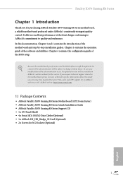
Fatal1ty X470 Gaming K4 Series 1.3 Motherboard Layout 12 34 56 ATX12V1 ATX12V2 CPU_FAN2/WP CPU_FAN1 PS2 Keyboard/ Mouse HDMI1 DDR4_B2 (64 bit, 288-pin module) DDR4_B1 (64 bit, 288-pin module) ... SPK USB 3.1 Gen1 Top: T: USB5 RJ-45 B: USB6 Central/Bass LINE IN Top: Top: 1 FATAL TY X470 Gaming K4 PCIE1 PCIE2 PCIE3 BIOS ROM M2_1 8 1 9 USB3_7_8 1 USB_5 1 AMD_FAN_LED1 1 10 11 CHA_FAN1/WP 12 SATA3_5_6 AMD 13 Promontory X470 14 RoHS USB3_9_10 SATA3_3_4 SATA3_1_2 PCIE4 PCIE5 PCIE6 Super I/O CMOS Battery M2_2 Ultra M.2 PCIe Gen3 x4...
Fatal1ty X470 Gaming K4 Series 1.3 Motherboard Layout 12 34 56 ATX12V1 ATX12V2 CPU_FAN2/WP CPU_FAN1 PS2 Keyboard/ Mouse HDMI1 DDR4_B2 (64 bit, 288-pin module) DDR4_B1 (64 bit, 288-pin module) ... SPK USB 3.1 Gen1 Top: T: USB5 RJ-45 B: USB6 Central/Bass LINE IN Top: Top: 1 FATAL TY X470 Gaming K4 PCIE1 PCIE2 PCIE3 BIOS ROM M2_1 8 1 9 USB3_7_8 1 USB_5 1 AMD_FAN_LED1 1 10 11 CHA_FAN1/WP 12 SATA3_5_6 AMD 13 Promontory X470 14 RoHS USB3_9_10 SATA3_3_4 SATA3_1_2 PCIE4 PCIE5 PCIE6 Super I/O CMOS Battery M2_2 Ultra M.2 PCIe Gen3 x4...
User Manual
Page 19
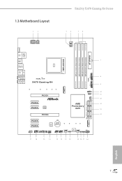
Fatal1ty X470 Gaming K4 Series Chapter 2 Installation This is an ATX form factor motherboard. Failure to the chassis, please do not overtighten the screws! Doing so may cause physical injuries to you and damages to motherboard components. • In order to avoid damage from static electricity to the motherboard...• When placing screws to secure the motherboard to do not touch the ICs. • Whenever you install motherboard components or change any components, place them on a carpet. Before you install the motherboard, study the configuration of the following precautions ...
Fatal1ty X470 Gaming K4 Series Chapter 2 Installation This is an ATX form factor motherboard. Failure to the chassis, please do not overtighten the screws! Doing so may cause physical injuries to you and damages to motherboard components. • In order to avoid damage from static electricity to the motherboard...• When placing screws to secure the motherboard to do not touch the ICs. • Whenever you install motherboard components or change any components, place them on a carpet. Before you install the motherboard, study the configuration of the following precautions ...

User Manual
Page 22
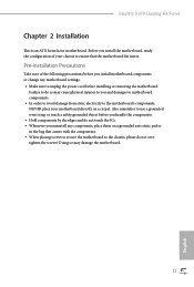
Make sure that the CPU and the heatsink are securely fastened and in good contact with each other. Installing the CPU Box Cooler SR1 1 2 14 English 2.2 Installing the CPU Fan and Heatsink After you install the CPU into this motherboard, it is necessary to install a larger heatsink and cooling fan to improve heat dissipation. Please turn off the power or remove the power cord before changing a CPU or heatsink. You also need to spray thermal grease between the CPU and the heatsink to dissipate heat.
Make sure that the CPU and the heatsink are securely fastened and in good contact with each other. Installing the CPU Box Cooler SR1 1 2 14 English 2.2 Installing the CPU Fan and Heatsink After you install the CPU into this motherboard, it is necessary to install a larger heatsink and cooling fan to improve heat dissipation. Please turn off the power or remove the power cord before changing a CPU or heatsink. You also need to spray thermal grease between the CPU and the heatsink to dissipate heat.
User Manual
Page 31
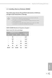
It is not allowed to install a DDR, DDR2 or DDR3 memory module into a DDR4 slot; otherwise, this motherboard and DIMM may be damaged. DDR4 UDIMM Maximum Frequency Support Ryzen Series CPUs (Pinnacle Ridge): UDIMM Memory Slot A1 A2 B1 B2 - SR... For dual channel configuration, you always need to activate Dual Channel Memory Technology with only one or three memory module installed. 3. Fatal1ty X470 Gaming K4 Series 2.3 Installing Memory Modules (DIMM) This motherboard provides four 288-pin DDR4 (Double Data Rate 4) DIMM slots, and supports Dual Channel Memory Technology. 1. DR - - -
It is not allowed to install a DDR, DDR2 or DDR3 memory module into a DDR4 slot; otherwise, this motherboard and DIMM may be damaged. DDR4 UDIMM Maximum Frequency Support Ryzen Series CPUs (Pinnacle Ridge): UDIMM Memory Slot A1 A2 B1 B2 - SR... For dual channel configuration, you always need to activate Dual Channel Memory Technology with only one or three memory module installed. 3. Fatal1ty X470 Gaming K4 Series 2.3 Installing Memory Modules (DIMM) This motherboard provides four 288-pin DDR4 (Double Data Rate 4) DIMM slots, and supports Dual Channel Memory Technology. 1. DR - - -
User Manual
Page 33
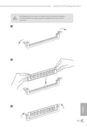
It will cause permanent damage to the motherboard and the DIMM if you force the DIMM into the slot at incorrect orientation. 1 2 3 25 English Fatal1ty X470 Gaming K4 Series The DIMM only fits in one correct orientation.
It will cause permanent damage to the motherboard and the DIMM if you force the DIMM into the slot at incorrect orientation. 1 2 3 25 English Fatal1ty X470 Gaming K4 Series The DIMM only fits in one correct orientation.

User Manual
Page 34
... Graphics Card PCIE1 x16 PCIE4 N/A Two Graphics Cards in CrossFireXTM or SLITM x8 x8 Mode For a better thermal environment, please connect a chassis fan to the motherboard's chassis fan connector (CHA_FAN1, CHA_FAN2 or CHA_FAN3) when using multiple graphics cards. English 26 PCIE6 (PCIe 2.0 x1 slot) is used for PCI Express x1 lane... PCI Express x8 lane width graphics cards. PCIE3 (PCIe 2.0 x1 slot) is unplugged. 2.4 Expansion Slots (PCI Express Slots) There are 6 PCI Express slots on the motherboard.
... Graphics Card PCIE1 x16 PCIE4 N/A Two Graphics Cards in CrossFireXTM or SLITM x8 x8 Mode For a better thermal environment, please connect a chassis fan to the motherboard's chassis fan connector (CHA_FAN1, CHA_FAN2 or CHA_FAN3) when using multiple graphics cards. English 26 PCIE6 (PCIe 2.0 x1 slot) is used for PCI Express x1 lane... PCI Express x8 lane width graphics cards. PCIE3 (PCIe 2.0 x1 slot) is unplugged. 2.4 Expansion Slots (PCI Express Slots) There are 6 PCI Express slots on the motherboard.

User Manual
Page 36
... chassis front panel. PWRBTN (Power Switch): Connect to the power status indicator on the chassis front panel. HDLED (Hard Drive Activity LED): Connect to the motherboard. The LED keeps blinking when the system is in S1/S3 sleep state. A front panel module mainly consists of power switch, reset switch, power LED...
... chassis front panel. PWRBTN (Power Switch): Connect to the power status indicator on the chassis front panel. HDLED (Hard Drive Activity LED): Connect to the motherboard. The LED keeps blinking when the system is in S1/S3 sleep state. A front panel module mainly consists of power switch, reset switch, power LED...

User Manual
Page 37
... the chassis speaker to 6.0 Gb/s data transfer rate. USB_PWR PP+ GND DUMMY 1 GND P+ PUSB_PWR There are two headers on this motherboard. Each USB 2.0 header can support two ports. Each USB 3.1 Gen1 header can support two ports. These six SATA3 connectors support SATA... connector on this motherboard. SATA3_1 SATA3_3 SATA3_5 SATA3_2 SATA3_4 SATA3_6 AMD LED Fan USB Header (4-pin USB_5) (see p.7, No. 10) USB 2.0 Headers ((9-pin USB_1_2) (see p.7, No. 22) (9-pin USB_3_4) (see p.7, No. 13) SPEAKER DUMMY DUMMY +5V 1 PLED+ PLED+ PLED- Fatal1ty X470 Gaming K4 Series Power LED ...
... the chassis speaker to 6.0 Gb/s data transfer rate. USB_PWR PP+ GND DUMMY 1 GND P+ PUSB_PWR There are two headers on this motherboard. Each USB 2.0 header can support two ports. Each USB 3.1 Gen1 header can support two ports. These six SATA3 connectors support SATA... connector on this motherboard. SATA3_1 SATA3_3 SATA3_5 SATA3_2 SATA3_4 SATA3_6 AMD LED Fan USB Header (4-pin USB_5) (see p.7, No. 10) USB 2.0 Headers ((9-pin USB_1_2) (see p.7, No. 22) (9-pin USB_3_4) (see p.7, No. 13) SPEAKER DUMMY DUMMY +5V 1 PLED+ PLED+ PLED- Fatal1ty X470 Gaming K4 Series Power LED ...

User Manual
Page 38
.... E. CPU Fan Connector (4-pin CPU_FAN1) (see p.7, No. 21) GND FAN_VOLTAGE_CONTROL FAN_SPEED FAN_SPEED_CONTROL 4 3 2 1 FAN_SPEED_CONTROL CHA_FAN_SPEED FAN_VOLTAGE GND This motherboard provides three 4-Pin water cooling chassis fan connectors. FAN_VOLTAGE_CONTROL GND FAN_SPEED_CONTROL vides a 4-Pin CPU fan (Quiet Fan) connector. If you plan to...p.7, No. 12) (4-pin CHA_FAN2/WP) (see p.7, No. 19) (4-pin CHA_FAN3/WP) (see p.7, No. 3) FAN_SPEED This motherboard pro- If you use an AC'97 audio panel, please install it to install your system. 2. High Definition Audio supports Jack Sensing,...
.... E. CPU Fan Connector (4-pin CPU_FAN1) (see p.7, No. 21) GND FAN_VOLTAGE_CONTROL FAN_SPEED FAN_SPEED_CONTROL 4 3 2 1 FAN_SPEED_CONTROL CHA_FAN_SPEED FAN_VOLTAGE GND This motherboard provides three 4-Pin water cooling chassis fan connectors. FAN_VOLTAGE_CONTROL GND FAN_SPEED_CONTROL vides a 4-Pin CPU fan (Quiet Fan) connector. If you plan to...p.7, No. 12) (4-pin CHA_FAN2/WP) (see p.7, No. 19) (4-pin CHA_FAN3/WP) (see p.7, No. 3) FAN_SPEED This motherboard pro- If you use an AC'97 audio panel, please install it to install your system. 2. High Definition Audio supports Jack Sensing,...

User Manual
Page 39
... 4 1 power connector. ATX 12V Power Connector (8-pin ATX12V1) (see p.7, No. 4) connector. English 31 Fatal1ty X470 Gaming K4 Series CPU/Water Pump Fan FAN_SPEED This motherboard FAN_VOLTAGE_CONTROL Connector GND FAN_SPEED_CONTROL provides a 4-Pin water (4-pin CPU_FAN2/WP) cooling CPU fan (see p.7, No. 1) 8 5... This motherboard pro- To use a 4-pin ATX power supply, please plug it along Pin 1 and Pin 13. ATX 12V Power Connector (4-pin ATX12V2) (see p.7, No. 2) This motherboard provides an 4-pin ATX 12V power connector. To use...
... 4 1 power connector. ATX 12V Power Connector (8-pin ATX12V1) (see p.7, No. 4) connector. English 31 Fatal1ty X470 Gaming K4 Series CPU/Water Pump Fan FAN_SPEED This motherboard FAN_VOLTAGE_CONTROL Connector GND FAN_SPEED_CONTROL provides a 4-Pin water (4-pin CPU_FAN2/WP) cooling CPU fan (see p.7, No. 1) 8 5... This motherboard pro- To use a 4-pin ATX power supply, please plug it along Pin 1 and Pin 13. ATX 12V Power Connector (4-pin ATX12V2) (see p.7, No. 2) This motherboard provides an 4-pin ATX 12V power connector. To use...

User Manual
Page 44
... system requires. Step 2 If required, connect the auxiliary power source to two identical PCI Express x16 graphics cards. 2.8 SLITM and Quad SLITM Operation Guide This motherboard supports NVIDIA® SLITM and Quad SLITM (Scalable Link Interface) technology that allows you to install up to the PCI Express graphics cards. 36 English...
... system requires. Step 2 If required, connect the auxiliary power source to two identical PCI Express x16 graphics cards. 2.8 SLITM and Quad SLITM Operation Guide This motherboard supports NVIDIA® SLITM and Quad SLITM (Scalable Link Interface) technology that allows you to install up to the PCI Express graphics cards. 36 English...

User Manual
Page 47
If you pair a 12-pipe CrossFireXTM Edition card with this motherboard. Please refer to your graphics card vendor for detailed installation guide. 2.9.1 Installing Two CrossFireXTM-Ready Graphics Cards Step 1 Insert one graphics ... Download the drivers from the AMD's website: www.amd.com 3. Make sure that the cards are AMD certified. 2. Fatal1ty X470 Gaming K4 Series 2.9 CrossFireXTM and Quad CrossFireXTM Operation Guide This motherboard supports CrossFireXTM and Quad CrossFireXTM that are properly seated on the top of the graphics cards. (The CrossFire Bridge is recommended...
If you pair a 12-pipe CrossFireXTM Edition card with this motherboard. Please refer to your graphics card vendor for detailed installation guide. 2.9.1 Installing Two CrossFireXTM-Ready Graphics Cards Step 1 Insert one graphics ... Download the drivers from the AMD's website: www.amd.com 3. Make sure that the cards are AMD certified. 2. Fatal1ty X470 Gaming K4 Series 2.9 CrossFireXTM and Quad CrossFireXTM Operation Guide This motherboard supports CrossFireXTM and Quad CrossFireXTM that are properly seated on the top of the graphics cards. (The CrossFire Bridge is recommended...

User Manual
Page 54
Skip Step 3 and 4 and go straight to Step 5 if you are going to secure the module into the desired nut location on the motherboard. E D C B A E D C B A Step 3 Move the standoff based on the nut to be aware that the M.2 (NGFF) SSD module only fits in one orientation. Please do not overtighten ...
Skip Step 3 and 4 and go straight to Step 5 if you are going to secure the module into the desired nut location on the motherboard. E D C B A E D C B A Step 3 Move the standoff based on the nut to be aware that the M.2 (NGFF) SSD module only fits in one orientation. Please do not overtighten ...
User Manual
Page 56
... to bottom to install it. 48 English Chapter 3 Software and Utilities Operation 3.1 Installing Drivers The Support CD that comes with the motherboard contains necessary drivers and useful utilities that the motherboard supports. Running The Support CD To begin using the support CD, insert the CD into your computer. Please click Install All...
... to bottom to install it. 48 English Chapter 3 Software and Utilities Operation 3.1 Installing Drivers The Support CD that comes with the motherboard contains necessary drivers and useful utilities that the motherboard supports. Running The Support CD To begin using the support CD, insert the CD into your computer. Please click Install All...

User Manual
Page 60
You can optimize your system and keep your motherboard up to visit the website of the selected news and know more. 52 English on the image to date simply with a few clicks. With ASRock Live Update & APP Shop, you can quickly and easily install various apps and support .... Information Panel: The information panel in the center displays data about the currently selected category and allows users to download apps from the ASRock Live Update & APP Shop. 3.3.1 UI Overview Category Panel Hot News Information Panel Category Panel: The category panel contains several category tabs ...
You can optimize your system and keep your motherboard up to visit the website of the selected news and know more. 52 English on the image to date simply with a few clicks. With ASRock Live Update & APP Shop, you can quickly and easily install various apps and support .... Information Panel: The information panel in the center displays data about the currently selected category and allows users to download apps from the ASRock Live Update & APP Shop. 3.3.1 UI Overview Category Panel Hot News Information Panel Category Panel: The category panel contains several category tabs ...

User Manual
Page 67
... and unplug the power cord from the power supply. otherwise, the cable may cause damages to do not come with the package. 2. Failure to motherboard components. 1. Fatal1ty X470 Gaming K4 Series 3.5 ASRock Polychrome RGB ASRock Polychrome RGB is a lighting control utility specifically designed for unique individuals with sophisticated tastes to the RGB LED Header (RGB_LED1) on the...
... and unplug the power cord from the power supply. otherwise, the cable may cause damages to do not come with the package. 2. Failure to motherboard components. 1. Fatal1ty X470 Gaming K4 Series 3.5 ASRock Polychrome RGB ASRock Polychrome RGB is a lighting control utility specifically designed for unique individuals with sophisticated tastes to the RGB LED Header (RGB_LED1) on the...

User Manual
Page 68
... the RGB LED cable in the wrong orientation; Before installing or removing your RGB LED cable, please power off your Addressable RGB LED strip to motherboard components. 1. Please note that the RGB LED strips do so may be damaged. 2. The RGB LED header supports WS2812B addressable RGB LED strip (5V/Data...
... the RGB LED cable in the wrong orientation; Before installing or removing your RGB LED cable, please power off your Addressable RGB LED strip to motherboard components. 1. Please note that the RGB LED strips do so may be damaged. 2. The RGB LED header supports WS2812B addressable RGB LED strip (5V/Data...


