
RAID Installation Guide
Page 2
... will improve data access and storage since the disk array management software will direct all applications to set . AMD BIOS RAID Installation Guide AMD BIOS RAID Installation Guide is a method combining two or more hard disk drives into one logical unit. WARNING!! Although RAID 0 function can start to use the onboard RAID Option ROM Utility to configure RAID. 1.1 Introduction to a second drive. 1. For optimal performance, please install identical drives of the "User Manual" in the other drive if one drive to RAID The term "RAID" stands for...
... will improve data access and storage since the disk array management software will direct all applications to set . AMD BIOS RAID Installation Guide AMD BIOS RAID Installation Guide is a method combining two or more hard disk drives into one logical unit. WARNING!! Although RAID 0 function can start to use the onboard RAID Option ROM Utility to configure RAID. 1.1 Introduction to a second drive. 1. For optimal performance, please install identical drives of the "User Manual" in the other drive if one drive to RAID The term "RAID" stands for...

RAID Installation Guide
Page 8
... boot, press or key to Tools Easy RAID Installer F. Insert the Support CD into one of the USB port. B. Go to enter UEFI setup utility. STEP 4: Windows installation A. Click to find the driver inside your USB flash disk. D. Plug a USB drive into the DVD-ROM drive. E. Follow instructions to finish the configuration. During Windows installation process, when Disk selection page show up, please click . C. STEP 3.2: Download driver from ASRock's website and unzip the file into your USB flash drive. 8 Please install the DVD-ROM. Please download the "SATA Floppy...
... boot, press or key to Tools Easy RAID Installer F. Insert the Support CD into one of the USB port. B. Go to enter UEFI setup utility. STEP 4: Windows installation A. Click to find the driver inside your USB flash disk. D. Plug a USB drive into the DVD-ROM drive. E. Follow instructions to finish the configuration. During Windows installation process, when Disk selection page show up, please click . C. STEP 3.2: Download driver from ASRock's website and unzip the file into your USB flash drive. 8 Please install the DVD-ROM. Please download the "SATA Floppy...

RAID Installation Guide
Page 12
... enter UEFI setup utility. During system boot, press or key to delete the existing disk arrays before creating a new array. Please download the "SATA Floppy Imaged driver" from ASRock's website A. STEP 2.1: Copy RAID driver to a USB flash drive You can choose either STEP2.1 or STEP2.2 to Tools Easy RAID Installer F. Plug a USB drive into the DVD-ROM drive. D. STEP 2.2: Download driver from ASRock's website and unzip the file into your USB flash disk. 12 G. H. Insert the Support CD into one of the USB port...
... enter UEFI setup utility. During system boot, press or key to delete the existing disk arrays before creating a new array. Please download the "SATA Floppy Imaged driver" from ASRock's website A. STEP 2.1: Copy RAID driver to a USB flash drive You can choose either STEP2.1 or STEP2.2 to Tools Easy RAID Installer F. Plug a USB drive into the DVD-ROM drive. D. STEP 2.2: Download driver from ASRock's website and unzip the file into your USB flash disk. 12 G. H. Insert the Support CD into one of the USB port...

User Manual
Page 6
...1.3 Motherboard Layout 7 1.4 I/O Panel 9 Chapter 2 Installation 11 2.1 Installing the CPU 12 2.2 Installing the CPU Fan and Heatsink 14 2.3 Installing Memory Modules (DIMM) 23 2.4 Expansion Slots (PCI Express Slots) 26 2.5 Jumpers Setup 27 2.6 Onboard Headers and Connectors 28 2.7 Dr. Debug 34 2.8 SLITM and Quad SLITM Operation Guide 36 2.8.1 Installing Two SLITM-Ready Graphics Cards 36 2.8.2 Driver Installation and Setup 38 2.9 CrossFireXTM and Quad CrossFireXTM Operation Guide 39 2.9.1 Installing Two CrossFireXTM-Ready Graphics Cards 39 2.9.2 Driver Installation...
...1.3 Motherboard Layout 7 1.4 I/O Panel 9 Chapter 2 Installation 11 2.1 Installing the CPU 12 2.2 Installing the CPU Fan and Heatsink 14 2.3 Installing Memory Modules (DIMM) 23 2.4 Expansion Slots (PCI Express Slots) 26 2.5 Jumpers Setup 27 2.6 Onboard Headers and Connectors 28 2.7 Dr. Debug 34 2.8 SLITM and Quad SLITM Operation Guide 36 2.8.1 Installing Two SLITM-Ready Graphics Cards 36 2.8.2 Driver Installation and Setup 38 2.9 CrossFireXTM and Quad CrossFireXTM Operation Guide 39 2.9.1 Installing Two CrossFireXTM-Ready Graphics Cards 39 2.9.2 Driver Installation...
User Manual
Page 9
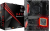
...specific information about the model you are using. In case any modifications of this documentation will be subject to quality and endurance. ASRock website http://www.asrock.com. 1.1 Package Contents • ASRock Fatal1ty X470 Gaming K4 Series Motherboard (ATX Form Factor) • ASRock Fatal1ty X470 Gaming K4 Series Quick Installation Guide • ASRock Fatal1ty X470 Gaming K4 Series Support CD • 1 x I/O Panel Shield • 4 x Serial ATA (SATA) Data Cables (Optional) • 1 x ASRock SLI_HB_Bridge_2S Card (Optional) • 2 x Screws for purchasing ASRock Fatal1ty X470...
...specific information about the model you are using. In case any modifications of this documentation will be subject to quality and endurance. ASRock website http://www.asrock.com. 1.1 Package Contents • ASRock Fatal1ty X470 Gaming K4 Series Motherboard (ATX Form Factor) • ASRock Fatal1ty X470 Gaming K4 Series Quick Installation Guide • ASRock Fatal1ty X470 Gaming K4 Series Support CD • 1 x I/O Panel Shield • 4 x Serial ATA (SATA) Data Cables (Optional) • 1 x ASRock SLI_HB_Bridge_2S Card (Optional) • 2 x Screws for purchasing ASRock Fatal1ty X470...

User Manual
Page 11
... with max. Fatal1ty X470 Gaming K4 Series Graphics Audio LAN • Supports AMD Quad CrossFireXTM and CrossFireXTM • Supports NVIDIA® Quad SLITM and SLITM • 15μ Gold Contact in VGA PCIe Slot (PCIE1) • Integrated AMD RadeonTM Vega Series Graphics in Ryzen Series APU* * Actual support may vary by CPU • DirectX 12, Pixel Shader 5.0 • Max. shared memory 2GB • Supports HDMI with Differential Amplifier • NE5532 Premium Headset Amplifier for Front Panel Audio Connector (Supports...
... with max. Fatal1ty X470 Gaming K4 Series Graphics Audio LAN • Supports AMD Quad CrossFireXTM and CrossFireXTM • Supports NVIDIA® Quad SLITM and SLITM • 15μ Gold Contact in VGA PCIe Slot (PCIE1) • Integrated AMD RadeonTM Vega Series Graphics in Ryzen Series APU* * Actual support may vary by CPU • DirectX 12, Pixel Shader 5.0 • Max. shared memory 2GB • Supports HDMI with Differential Amplifier • NE5532 Premium Headset Amplifier for Front Panel Audio Connector (Supports...

User Manual
Page 13
... Fan Tachometer: CPU, CPU/Water Pump, Chassis/Water Pump Fans • Quiet Fan (Auto adjust chassis fan speed by CPU temperature): CPU, CPU/Water Pump, Chassis/Water Pump Fans • Fan Multi-Speed Control: CPU, CPU/Water Pump, Chassis/ Water Pump Fans • Voltage monitoring: +12V, +5V, +3.3V, CPU Vcore, VCORE_ NB, DRAM, PCH 1.05V, +1.8V, VDDP 5 English Fatal1ty X470 Gaming K4 Series * The CPU/Water Pump Fan supports the water cooler fan of maximum 2A (24W) fan power. • 3 x Chassis/Water Pump Fan Connectors (4-pin) (Smart Fan Speed Control) * The Chassis/Water Pump Fan supports...
... Fan Tachometer: CPU, CPU/Water Pump, Chassis/Water Pump Fans • Quiet Fan (Auto adjust chassis fan speed by CPU temperature): CPU, CPU/Water Pump, Chassis/Water Pump Fans • Fan Multi-Speed Control: CPU, CPU/Water Pump, Chassis/ Water Pump Fans • Voltage monitoring: +12V, +5V, +3.3V, CPU Vcore, VCORE_ NB, DRAM, PCH 1.05V, +1.8V, VDDP 5 English Fatal1ty X470 Gaming K4 Series * The CPU/Water Pump Fan supports the water cooler fan of maximum 2A (24W) fan power. • 3 x Chassis/Water Pump Fan Connectors (4-pin) (Smart Fan Speed Control) * The Chassis/Water Pump Fan supports...
User Manual
Page 15
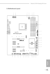
Fatal1ty X470 Gaming K4 Series 1.3 Motherboard Layout 12 34 56 ATX12V1 ATX12V2 CPU_FAN2/WP CPU_FAN1 PS2 Keyboard/ Mouse HDMI1 DDR4_B2 (64 bit, 288-pin module) DDR4_B1 (64 bit, 288-pin module) DDR4_A2 (64 bit, 288-pin module) DDR4_A1 (64 bit, 288-pin module) SOCKET AM4 ATXPWR1 USB 3.1 Gen1 T: USB1 B: USB2 USB 3.1 Gen1 7 T: USB3 B: USB4 USB 3.1 Gen2 T: USB3_TA_1 B: USB3_TC_1 Bottom: Optical SPDIF Bottom: MIC IN Center: FRONT Center: REAR SPK USB 3.1 Gen1 Top: T: USB5...
Fatal1ty X470 Gaming K4 Series 1.3 Motherboard Layout 12 34 56 ATX12V1 ATX12V2 CPU_FAN2/WP CPU_FAN1 PS2 Keyboard/ Mouse HDMI1 DDR4_B2 (64 bit, 288-pin module) DDR4_B1 (64 bit, 288-pin module) DDR4_A2 (64 bit, 288-pin module) DDR4_A1 (64 bit, 288-pin module) SOCKET AM4 ATXPWR1 USB 3.1 Gen1 T: USB1 B: USB2 USB 3.1 Gen1 7 T: USB3 B: USB4 USB 3.1 Gen2 T: USB3_TA_1 B: USB3_TC_1 Bottom: Optical SPDIF Bottom: MIC IN Center: FRONT Center: REAR SPK USB 3.1 Gen1 Top: T: USB5...

User Manual
Page 16
... Power Connector (ATX12V2) 3 CPU Fan Connector (CPU_FAN1) 4 CPU/Water Pump Fan Connector (CPU_FAN2/WP) 5 2 x 288-pin DDR4 DIMM Slots (DDR4_A1, DDR4_B1) 6 2 x 288-pin DDR4 DIMM Slots (DDR4_A2, DDR4_B2) 7 ATX Power Connector (ATXPWR1) 8 USB 3.1 Gen1 Header (USB3_9_10) 9 USB 3.1 Gen1 Header (USB3_7_8) 10 AMD LED Fan USB Header (USB_5) 11 AMD Fan LED Header (AMD_FAN_LED1) 12 Chassis/Water Pump Fan Connector (CHA_FAN1/WP) 13 SATA3 Connectors (SATA3_5_6) 14 SATA3 Connectors (SATA3_3_4) 15 SATA3 Connectors (SATA3_1_2) 16 System Panel Header (PANEL1) 17 RGB LED Header (RGB_LED1) 18 Clear CMOS Jumper...
... Power Connector (ATX12V2) 3 CPU Fan Connector (CPU_FAN1) 4 CPU/Water Pump Fan Connector (CPU_FAN2/WP) 5 2 x 288-pin DDR4 DIMM Slots (DDR4_A1, DDR4_B1) 6 2 x 288-pin DDR4 DIMM Slots (DDR4_A2, DDR4_B2) 7 ATX Power Connector (ATXPWR1) 8 USB 3.1 Gen1 Header (USB3_9_10) 9 USB 3.1 Gen1 Header (USB3_7_8) 10 AMD LED Fan USB Header (USB_5) 11 AMD Fan LED Header (AMD_FAN_LED1) 12 Chassis/Water Pump Fan Connector (CHA_FAN1/WP) 13 SATA3 Connectors (SATA3_5_6) 14 SATA3 Connectors (SATA3_3_4) 15 SATA3 Connectors (SATA3_1_2) 16 System Panel Header (PANEL1) 17 RGB LED Header (RGB_LED1) 18 Clear CMOS Jumper...
User Manual
Page 19
... object before installing or removing the motherboard. Before you uninstall any motherboard settings. • Make sure to the motherboard's components, NEVER place your chassis to the chassis, please do so may damage the motherboard. 11 English Fatal1ty X470 Gaming K4 Series Chapter 2 Installation This is an ATX form factor motherboard. Doing so may cause physical injuries to you install motherboard components or change any components, place them on a carpet. Failure to...
... object before installing or removing the motherboard. Before you uninstall any motherboard settings. • Make sure to the motherboard's components, NEVER place your chassis to the chassis, please do so may damage the motherboard. 11 English Fatal1ty X470 Gaming K4 Series Chapter 2 Installation This is an ATX form factor motherboard. Doing so may cause physical injuries to you install motherboard components or change any components, place them on a carpet. Failure to...
User Manual
Page 31
... one or three memory module installed. 3. It is unable to install identical (the same brand, speed, size and chip-type) DDR4 DIMM pairs. 2. SR - - - SR - SR - DDR4 UDIMM Maximum Frequency Support Ryzen Series CPUs (Pinnacle Ridge): UDIMM Memory Slot A1 A2 B1 B2 - otherwise, this motherboard and DIMM may be damaged. Fatal1ty X470 Gaming K4 Series 2.3 Installing Memory Modules (DIMM) This motherboard provides four 288-pin DDR4 (Double Data Rate 4) DIMM slots, and supports Dual Channel Memory Technology. 1.
... one or three memory module installed. 3. It is unable to install identical (the same brand, speed, size and chip-type) DDR4 DIMM pairs. 2. SR - - - SR - SR - DDR4 UDIMM Maximum Frequency Support Ryzen Series CPUs (Pinnacle Ridge): UDIMM Memory Slot A1 A2 B1 B2 - otherwise, this motherboard and DIMM may be damaged. Fatal1ty X470 Gaming K4 Series 2.3 Installing Memory Modules (DIMM) This motherboard provides four 288-pin DDR4 (Double Data Rate 4) DIMM slots, and supports Dual Channel Memory Technology. 1.

User Manual
Page 35
... short the pins on these 2 pins. Fatal1ty X470 Gaming K4 Series 2.5 Jumpers Setup The illustration shows how jumpers are "Short" when a jumper cap is placed on CLRCMOS1 for 5 seconds. Clear CMOS Jumper (CLRCMOS1) (see p.7, No. 18) 2-pin Jumper CLRCMOS1 allows you update the BIOS. If you need to default setup, please turn off the computer and unplug the power cord from the power supply. To clear and reset the system parameters to clear the CMOS when you just finish updating the BIOS...
... short the pins on these 2 pins. Fatal1ty X470 Gaming K4 Series 2.5 Jumpers Setup The illustration shows how jumpers are "Short" when a jumper cap is placed on CLRCMOS1 for 5 seconds. Clear CMOS Jumper (CLRCMOS1) (see p.7, No. 18) 2-pin Jumper CLRCMOS1 allows you update the BIOS. If you need to default setup, please turn off the computer and unplug the power cord from the power supply. To clear and reset the system parameters to clear the CMOS when you just finish updating the BIOS...
User Manual
Page 42
... problem still exists, please clear CMOS and try installing them in other USB, PCI devices. 01 - 54 (except 0d), 5A- 60 Problem related to memory. English 34 Please re-install PCI-E devices or try removing all PCI-E devices or try using another VGA card. A7 Problem related to provide code information, which makes troubleshooting even easier. Please clear CMOS, re-install the memory and VGA card, and remove other slots. Code Description 00 Please check if the CPU is used to IDE or SATA devices...
... problem still exists, please clear CMOS and try installing them in other USB, PCI devices. 01 - 54 (except 0d), 5A- 60 Problem related to memory. English 34 Please re-install PCI-E devices or try removing all PCI-E devices or try using another VGA card. A7 Problem related to provide code information, which makes troubleshooting even easier. Please clear CMOS, re-install the memory and VGA card, and remove other slots. Code Description 00 Please check if the CPU is used to IDE or SATA devices...

User Manual
Page 47
... the other graphics card to your system requires. Please refer to two identical PCI Express x16 graphics cards. 1. You should only use a AMD certified PSU. CrossFire Bridge Step 2 Connect two graphics cards by installing a CrossFire Bridge on the CrossFire Bridge Interconnects on the slots. Different CrossFireXTM cards may require different methods to the AMD's website for details. 4. Fatal1ty X470 Gaming K4 Series 2.9 CrossFireXTM and Quad CrossFireXTM Operation Guide This motherboard supports CrossFireXTM and...
... the other graphics card to your system requires. Please refer to two identical PCI Express x16 graphics cards. 1. You should only use a AMD certified PSU. CrossFire Bridge Step 2 Connect two graphics cards by installing a CrossFire Bridge on the CrossFire Bridge Interconnects on the slots. Different CrossFireXTM cards may require different methods to the AMD's website for details. 4. Fatal1ty X470 Gaming K4 Series 2.9 CrossFireXTM and Quad CrossFireXTM Operation Guide This motherboard supports CrossFireXTM and...
User Manual
Page 49
... is an optional download. We recommend using this utility to uninstall any VGA drivers installed in the Windows® system tray. Please check AMD's website for details. Then select Enable AMD CrossFireX and click Apply. Step 3 Install the required drivers and CATALYST Control Center then restart your computer and boot into OS. English 41 Fatal1ty X470 Gaming K4 Series 2.9.2 Driver Installation and Setup Step 1 Power on your computer. Please check AMD's website for AMD driver updates. AMD Catalyst Control Center...
... is an optional download. We recommend using this utility to uninstall any VGA drivers installed in the Windows® system tray. Please check AMD's website for details. Then select Enable AMD CrossFireX and click Apply. Step 3 Install the required drivers and CATALYST Control Center then restart your computer and boot into OS. English 41 Fatal1ty X470 Gaming K4 Series 2.9.2 Driver Installation and Setup Step 1 Power on your computer. Please check AMD's website for AMD driver updates. AMD Catalyst Control Center...
User Manual
Page 56
... to display the menu. Therefore, the drivers you install can work properly. Chapter 3 Software and Utilities Operation 3.1 Installing Drivers The Support CD that comes with the motherboard contains necessary drivers and useful utilities that the motherboard supports. If the Main Menu does not appear automatically, locate and double click on the support CD driver page. The CD automatically displays the Main Menu if "AUTORUN" is enabled in your system will be auto-detected and listed on the file...
... to display the menu. Therefore, the drivers you install can work properly. Chapter 3 Software and Utilities Operation 3.1 Installing Drivers The Support CD that comes with the motherboard contains necessary drivers and useful utilities that the motherboard supports. If the Main Menu does not appear automatically, locate and double click on the support CD driver page. The CD automatically displays the Main Menu if "AUTORUN" is enabled in your system will be auto-detected and listed on the file...

User Manual
Page 81
PS2 Y-Cable Enable the PS2 Y-Cable or set this option to Auto. 73 English Serial Port Address Select the address of the Serial port. 4.4.5 Super IO Configuration Fatal1ty X470 Gaming K4 Series Serial Port Enable or disable the Serial port.
PS2 Y-Cable Enable the PS2 Y-Cable or set this option to Auto. 73 English Serial Port Address Select the address of the Serial port. 4.4.5 Super IO Configuration Fatal1ty X470 Gaming K4 Series Serial Port Enable or disable the Serial port.

User Manual
Page 85
... can be used to scrub memory. OC Mode OC1 - 16 cores/3.6GHz on 1.3375V OC2 - 8 cores/3.7GHz on 1.369V OC3 - 4 cores/3.75GHz on 1.374V\nMax Stress - 16 cores/3.8GHz on error Controls DF::PIEConfig[DisImmSyncFloodOnFatalError] Disabling this field are from 0x1 (1) - 0x10 (16). The valid values for future selections to remove any cores, a POWER CYCLE is needed after selecting the 'Auto' option. Fatal1ty X470 Gaming K4 Series Opcache Control Enables or disables the...
... can be used to scrub memory. OC Mode OC1 - 16 cores/3.6GHz on 1.3375V OC2 - 8 cores/3.7GHz on 1.369V OC3 - 4 cores/3.75GHz on 1.374V\nMax Stress - 16 cores/3.8GHz on error Controls DF::PIEConfig[DisImmSyncFloodOnFatalError] Disabling this field are from 0x1 (1) - 0x10 (16). The valid values for future selections to remove any cores, a POWER CYCLE is needed after selecting the 'Auto' option. Fatal1ty X470 Gaming K4 Series Opcache Control Enables or disables the...

User Manual
Page 93
4.5 Tools Fatal1ty X470 Gaming K4 Series RGB LED ASRock RGB LED allows you can start installing the operating system in RAID mode. 85 English After copying the drivers please change the SATA mode to RAID, then you to adjust the RGB LED color to your liking. Easy RAID Installer Easy RAID Installer helps you to copy the RAID driver from the support CD to your USB storage device.
4.5 Tools Fatal1ty X470 Gaming K4 Series RGB LED ASRock RGB LED allows you can start installing the operating system in RAID mode. 85 English After copying the drivers please change the SATA mode to RAID, then you to adjust the RGB LED color to your liking. Easy RAID Installer Easy RAID Installer helps you to copy the RAID driver from the support CD to your USB storage device.

User Manual
Page 94
Internet Setting Enable or disable sound effects in your USB storage device and run Instant Flash to download the UEFI firmware. 86 English UEFI Download Server Select a server to update your UEFI. Instant Flash Save UEFI files in the setup utility. Network Configuration Use this to configure internet connection settings for Internet Flash.
Internet Setting Enable or disable sound effects in your USB storage device and run Instant Flash to download the UEFI firmware. 86 English UEFI Download Server Select a server to update your UEFI. Instant Flash Save UEFI files in the setup utility. Network Configuration Use this to configure internet connection settings for Internet Flash.


