
User Manual
Page 2
... www.dtsc.ca.gov/hazardouswaste/ perchlorate" ASRock Website: http://www.asrock.com Version 1.0 Published April 2017 Copyright©2017 ASRock INC. Products and corporate names appearing in this documentation may or may appear in this motherboard contains Perchlorate, a toxic substance controlled in... advance. With respect to the implied warranties or conditions of ASRock Inc. All rights reserved. CALIFORNIA, USA ONLY The Lithium battery...
... www.dtsc.ca.gov/hazardouswaste/ perchlorate" ASRock Website: http://www.asrock.com Version 1.0 Published April 2017 Copyright©2017 ASRock INC. Products and corporate names appearing in this documentation may or may appear in this motherboard contains Perchlorate, a toxic substance controlled in... advance. With respect to the implied warranties or conditions of ASRock Inc. All rights reserved. CALIFORNIA, USA ONLY The Lithium battery...

User Manual
Page 6
Contents Chapter 1 Introduction 1 1.1 Package Contents 1 1.2 Specifications 2 1.3 Motherboard Layout 7 1.4 I/O Panel 9 Chapter 2 Installation 11 2.1 Installing the CPU 12 2.2 Installing the CPU Fan and Heatsink 14 2.3 Installing Memory Modules (DIMM) 23 2.4 Expansion Slots (PCI Express ...
Contents Chapter 1 Introduction 1 1.1 Package Contents 1 1.2 Specifications 2 1.3 Motherboard Layout 7 1.4 I/O Panel 9 Chapter 2 Installation 11 2.1 Installing the CPU 12 2.2 Installing the CPU Fan and Heatsink 14 2.3 Installing Memory Modules (DIMM) 23 2.4 Expansion Slots (PCI Express ...

User Manual
Page 9
... support list on ASRock's website without notice. ASRock website http://www.asrock.com. 1.1 Package Contents • ASRock Fatal1ty X370 Gaming X Series Motherboard (ATX Form Factor) • ASRock Fatal1ty X370 Gaming X Series Quick Installation Guide • ASRock Fatal1ty X370 Gaming X Series Support CD • 1 x I/O Panel Shield • 4 x Serial ATA (SATA) Data Cables (Optional) • 1 x ASRock SLI_HB_Bridge_2S Card (Optional) • 3 x Screws for purchasing ASRock Fatal1ty X370 Gaming X Series motherboard, a reliable motherboard produced under ASRock's consistently stringent...
... support list on ASRock's website without notice. ASRock website http://www.asrock.com. 1.1 Package Contents • ASRock Fatal1ty X370 Gaming X Series Motherboard (ATX Form Factor) • ASRock Fatal1ty X370 Gaming X Series Quick Installation Guide • ASRock Fatal1ty X370 Gaming X Series Support CD • 1 x I/O Panel Shield • 4 x Serial ATA (SATA) Data Cables (Optional) • 1 x ASRock SLI_HB_Bridge_2S Card (Optional) • 3 x Screws for purchasing ASRock Fatal1ty X370 Gaming X Series motherboard, a reliable motherboard produced under ASRock's consistently stringent...
User Manual
Page 15
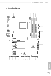
Fatal1ty X370 Gaming X Series 1.3 Motherboard Layout Bottom: Optical SPDIF 1 2 3 45 CPU_OPT/W_PUMP CPU_FAN1 PS2 Mouse PS2 Keyboard X370 Gaming X HDMI1 SOCKET AM4 USB 3.0 T: USB1 B: USB2 USB 3.0 T: USB3 B: USB4 USB 3.0 T: USB3_TA_1 B: USB3_TC_1 USB 3.0 T: USB5 ...module) DDR4_B2 (64 bit, 288-pin module) 6 7 USB3_9_10 1 1 USB_5 1 AMD_FAN_LED1 1 USB3_7_8 8 9 10 CHA_FAN1 11 SATA3_5_6 12 AMD Promontory X370 13 SATA3_3_4 14 ATXPWR1 SATA3_1_2 M2_2 PCIE5 PCIE6 HD_AUDIO1 COM1 1 1 1 TPMS1 SPK_PLED1 1 26 25 24 23 Super I/O CMOS Battery USB_3_4 USB_1_2 1 ...
Fatal1ty X370 Gaming X Series 1.3 Motherboard Layout Bottom: Optical SPDIF 1 2 3 45 CPU_OPT/W_PUMP CPU_FAN1 PS2 Mouse PS2 Keyboard X370 Gaming X HDMI1 SOCKET AM4 USB 3.0 T: USB1 B: USB2 USB 3.0 T: USB3 B: USB4 USB 3.0 T: USB3_TA_1 B: USB3_TC_1 USB 3.0 T: USB5 ...module) DDR4_B2 (64 bit, 288-pin module) 6 7 USB3_9_10 1 1 USB_5 1 AMD_FAN_LED1 1 USB3_7_8 8 9 10 CHA_FAN1 11 SATA3_5_6 12 AMD Promontory X370 13 SATA3_3_4 14 ATXPWR1 SATA3_1_2 M2_2 PCIE5 PCIE6 HD_AUDIO1 COM1 1 1 1 TPMS1 SPK_PLED1 1 26 25 24 23 Super I/O CMOS Battery USB_3_4 USB_1_2 1 ...

User Manual
Page 19
Fatal1ty X370 Gaming X Series Chapter 2 Installation This is a ATX form factor motherboard. Also remember to use a grounded wrist strap or touch a safety grounded object before you handle the components. • Hold components by the edges and do not touch the ICs. • Whenever you uninstall any motherboard... settings. • Make sure to unplug the power cord before you and damages to motherboard components. • In order to avoid damage from static electricity to the motherboard's components, NEVER place your chassis to do...
Fatal1ty X370 Gaming X Series Chapter 2 Installation This is a ATX form factor motherboard. Also remember to use a grounded wrist strap or touch a safety grounded object before you handle the components. • Hold components by the edges and do not touch the ICs. • Whenever you uninstall any motherboard... settings. • Make sure to unplug the power cord before you and damages to motherboard components. • In order to avoid damage from static electricity to the motherboard's components, NEVER place your chassis to do...

User Manual
Page 22
You also need to spray thermal grease between the CPU and the heatsink to dissipate heat. 2.2 Installing the CPU Fan and Heatsink After you install the CPU into this motherboard, it is necessary to install a larger heatsink and cooling fan to improve heat dissipation. Make sure that the CPU and the heatsink are securely fastened and in good contact with each other. Installing the CPU Box Cooler SR1 1 2 14 English Please turn off the power or remove the power cord before changing a CPU or heatsink.
You also need to spray thermal grease between the CPU and the heatsink to dissipate heat. 2.2 Installing the CPU Fan and Heatsink After you install the CPU into this motherboard, it is necessary to install a larger heatsink and cooling fan to improve heat dissipation. Make sure that the CPU and the heatsink are securely fastened and in good contact with each other. Installing the CPU Box Cooler SR1 1 2 14 English Please turn off the power or remove the power cord before changing a CPU or heatsink.

User Manual
Page 31
otherwise, this motherboard and DIMM may be damaged. SR - SR - - 2667 - DR - DR SR SR SR SR SR/DR DR SR/DR DR 2400 2400 2400 2133 1866 ... English DR - - - SR 2667 - DR - It is unable to install identical (the same brand, speed, size and chip-type) DDR4 DIMM pairs. 2. Fatal1ty X370 Gaming X Series 2.3 Installing Memory Modules (DIMM) This motherboard provides four 288-pin DDR4 (Double Data Rate 4) DIMM slots, and supports Dual Channel Memory Technology. 1. DDR4 UDIMM Maximum Frequency Support A-Series...
otherwise, this motherboard and DIMM may be damaged. SR - SR - - 2667 - DR - DR SR SR SR SR SR/DR DR SR/DR DR 2400 2400 2400 2133 1866 ... English DR - - - SR 2667 - DR - It is unable to install identical (the same brand, speed, size and chip-type) DDR4 DIMM pairs. 2. Fatal1ty X370 Gaming X Series 2.3 Installing Memory Modules (DIMM) This motherboard provides four 288-pin DDR4 (Double Data Rate 4) DIMM slots, and supports Dual Channel Memory Technology. 1. DDR4 UDIMM Maximum Frequency Support A-Series...

User Manual
Page 32
It will cause permanent damage to the motherboard and the DIMM if you force the DIMM into the slot at incorrect orientation. 1 2 3 24 English The DIMM only fits in one correct orientation.
It will cause permanent damage to the motherboard and the DIMM if you force the DIMM into the slot at incorrect orientation. 1 2 3 24 English The DIMM only fits in one correct orientation.
User Manual
Page 33
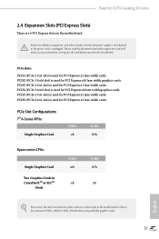
... N/A x8 English For a better thermal environment, please connect a chassis fan to the motherboard's chassis fan connector (CHA_FAN1 or CHA_FAN2) when using multiple graphics cards. 25 Fatal1ty X370 Gaming X Series 2.4 Expansion Slots (PCI Express Slots) There are 6 PCI Express slots on the motherboard. PCIE4 (PCIe 3.0 x16 slot) is used for PCI Express x16 lane width graphics...
... N/A x8 English For a better thermal environment, please connect a chassis fan to the motherboard's chassis fan connector (CHA_FAN1 or CHA_FAN2) when using multiple graphics cards. 25 Fatal1ty X370 Gaming X Series 2.4 Expansion Slots (PCI Express Slots) There are 6 PCI Express slots on the motherboard. PCIE4 (PCIe 3.0 x16 slot) is used for PCI Express x16 lane width graphics...

User Manual
Page 35
... LED): Connect to the motherboard. The front panel design may configure the way to the reset switch on when the system is reading or writing data. Placing jumper caps over these headers and connectors. PLED (System Power LED): Connect to the power switch on the chassis front panel. Fatal1ty X370 Gaming X Series 2.6 Onboard Headers...
... LED): Connect to the motherboard. The front panel design may configure the way to the reset switch on when the system is reading or writing data. Placing jumper caps over these headers and connectors. PLED (System Power LED): Connect to the power switch on the chassis front panel. Fatal1ty X370 Gaming X Series 2.6 Onboard Headers...

User Manual
Page 36
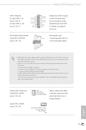
... support SATA data cables for connecting the USB connector on this header. P+ USB_PWR This header is used for internal storage devices with up to this motherboard. Each USB 2.0 header can support two ports. 28 English SATA3_2 SATA3_1 AMD LED Fan USB Header (4-pin USB_5) (see p.7, No. 12) SATA3_3 SATA3_4 SPEAKER DUMMY...
... support SATA data cables for connecting the USB connector on this header. P+ USB_PWR This header is used for internal storage devices with up to this motherboard. Each USB 2.0 header can support two ports. 28 English SATA3_2 SATA3_1 AMD LED Fan USB Header (4-pin USB_5) (see p.7, No. 12) SATA3_3 SATA3_4 SPEAKER DUMMY...
User Manual
Page 37
...front panel audio header by the steps below: A. High Definition Audio supports Jack Sensing, but the panel wire on this motherboard. Connect Ground (GND) to OUT2_L. You don't need to connect them for connecting audio devices to the front audio... Please follow the instructions in the Realtek Control panel and adjust "Recording Volume". Connect Audio_R (RIN) to OUT2_R and Audio_L (LIN) to Ground (GND). Fatal1ty X370 Gaming X Series USB 3.0 Header (19-pin USB3_7_8) (see p.7, No. 8) (19-pin USB3_9_10) (see p.7, No. 7) Vbus IntA_PA_SSRXIntA_PA_SSRX+ GND IntA_PA_SSTXIntA_PA_SSTX+ GND...
...front panel audio header by the steps below: A. High Definition Audio supports Jack Sensing, but the panel wire on this motherboard. Connect Ground (GND) to OUT2_L. You don't need to connect them for connecting audio devices to the front audio... Please follow the instructions in the Realtek Control panel and adjust "Recording Volume". Connect Audio_R (RIN) to OUT2_R and Audio_L (LIN) to Ground (GND). Fatal1ty X370 Gaming X Series USB 3.0 Header (19-pin USB3_7_8) (see p.7, No. 8) (19-pin USB3_9_10) (see p.7, No. 7) Vbus IntA_PA_SSRXIntA_PA_SSRX+ GND IntA_PA_SSTXIntA_PA_SSTX+ GND...

User Manual
Page 38
... vides an 8-pin ATX 12V power connector. CPU Fan Connectors (4-pin CPU_FAN1) (see p.7, No. 3) FAN_SPEED_CONTROL CPU_FAN_SPEED FAN_VOLTAGE GND 1 2 34 This motherboard provides a 4-Pin water cooling CPU fan connector. If you plan to Pin 1-3. CPU Optional/Water Pump Fan Connector (4-pin CPU_OPT/W_ PUMP) (see...plug it along Pin 1 and Pin 5. English 30 ATX 12V Power Connector (8-pin ATX12V1) (see p.7, No. 6) 12 24 1 13 This motherboard provides a 24-pin ATX power connector. Chassis Optional/Water Pump Fan Connector (4-pin CHA_FAN3/W_ PUMP) (see p.7, No. 19) 4 3 21...
... vides an 8-pin ATX 12V power connector. CPU Fan Connectors (4-pin CPU_FAN1) (see p.7, No. 3) FAN_SPEED_CONTROL CPU_FAN_SPEED FAN_VOLTAGE GND 1 2 34 This motherboard provides a 4-Pin water cooling CPU fan connector. If you plan to Pin 1-3. CPU Optional/Water Pump Fan Connector (4-pin CPU_OPT/W_ PUMP) (see...plug it along Pin 1 and Pin 5. English 30 ATX 12V Power Connector (8-pin ATX12V1) (see p.7, No. 6) 12 24 1 13 This motherboard provides a 24-pin ATX power connector. Chassis Optional/Water Pump Fan Connector (4-pin CHA_FAN3/W_ PUMP) (see p.7, No. 19) 4 3 21...

User Manual
Page 42
... graphics card to the PCI Express graphics cards. 34 English You should only use a NVIDIA® certified PSU. 2.8 SLITM and Quad SLITM Operation Guide This motherboard supports NVIDIA® SLITM and Quad SLITM (Scalable Link Interface) technology that allows you to install up to use identical SLITM-ready graphics cards that...
... graphics card to the PCI Express graphics cards. 34 English You should only use a NVIDIA® certified PSU. 2.8 SLITM and Quad SLITM Operation Guide This motherboard supports NVIDIA® SLITM and Quad SLITM (Scalable Link Interface) technology that allows you to install up to use identical SLITM-ready graphics cards that...

User Manual
Page 45
... minimum power your graphics card vendor for details.) 37 English If you pair a 12-pipe CrossFireXTM Edition card with this motherboard. Please refer to use identical CrossFireXTM-ready graphics cards that are properly seated on the top of the graphics cards. (The...to install up to PCIE3 slot. Make sure that your graphics card driver supports AMD CrossFireXTM technology. Fatal1ty X370 Gaming X Series 2.9 CrossFireXTM and Quad CrossFireXTM Operation Guide This motherboard supports CrossFireXTM and Quad CrossFireXTM that allows you purchase, not bundled with a 16-pipe card, both...
... minimum power your graphics card vendor for details.) 37 English If you pair a 12-pipe CrossFireXTM Edition card with this motherboard. Please refer to use identical CrossFireXTM-ready graphics cards that are properly seated on the top of the graphics cards. (The...to install up to PCIE3 slot. Make sure that your graphics card driver supports AMD CrossFireXTM technology. Fatal1ty X370 Gaming X Series 2.9 CrossFireXTM and Quad CrossFireXTM Operation Guide This motherboard supports CrossFireXTM and Quad CrossFireXTM that allows you purchase, not bundled with a 16-pipe card, both...

User Manual
Page 49
... the M.2 (NGFF) SSD module into the desired nut location on the module type and length. Hand tighten the standoff into the M.2 slot. D C B A D C B A D C B A C B A D NUT2 NUT1 Fatal1ty X370 Gaming X Series Step 3 Move the standoff based on the motherboard. Skip Step 3 and 4 and go straight to Step 5 if you are going to secure the module into place.
... the M.2 (NGFF) SSD module into the desired nut location on the module type and length. Hand tighten the standoff into the M.2 slot. D C B A D C B A D C B A C B A D NUT2 NUT1 Fatal1ty X370 Gaming X Series Step 3 Move the standoff based on the motherboard. Skip Step 3 and 4 and go straight to Step 5 if you are going to secure the module into place.
User Manual
Page 52
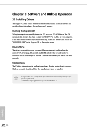
... 44 English Chapter 3 Software and Utilities Operation 3.1 Installing Drivers The Support CD that comes with the motherboard contains necessary drivers and useful utilities that the motherboard supports. Running The Support CD To begin using the support CD, insert the CD into your system...then follow the order from top to bottom to install it. Utilities Menu The Utilities Menu shows the application software that enhance the motherboard's features. To improve Windows 7 compatibility, please download and install the following hot fix provided by Microsoft. The CD automatically displays...
... 44 English Chapter 3 Software and Utilities Operation 3.1 Installing Drivers The Support CD that comes with the motherboard contains necessary drivers and useful utilities that the motherboard supports. Running The Support CD To begin using the support CD, insert the CD into your system...then follow the order from top to bottom to install it. Utilities Menu The Utilities Menu shows the application software that enhance the motherboard's features. To improve Windows 7 compatibility, please download and install the following hot fix provided by Microsoft. The CD automatically displays...

User Manual
Page 56
...that when selected the information panel below displays the relative information. 3.3 ASRock Live Update & APP Shop The ASRock Live Update & APP Shop is an online store for purchasing and downloading software applications for your motherboard up to date simply with a few clicks. You can optimize ...your system and keep your ASRock computer. on the image to perform job-related tasks. Information Panel: The information ...
...that when selected the information panel below displays the relative information. 3.3 ASRock Live Update & APP Shop The ASRock Live Update & APP Shop is an online store for purchasing and downloading software applications for your motherboard up to date simply with a few clicks. You can optimize ...your system and keep your ASRock computer. on the image to perform job-related tasks. Information Panel: The information ...
User Manual
Page 63
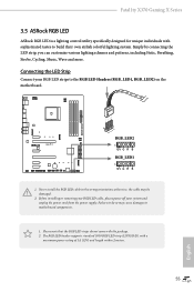
... G R B 1. Failure to the RGB LED Headers (RGB_LED1, RGB_LED2) on the motherboard. Please note that the RGB LED strips do so may be damaged. 2. Fatal1ty X370 Gaming X Series 3.5 ASRock RGB LED ASRock RGB LED is a lighting control utility specifically designed for unique individuals with sophisticated tastes to motherboard components. 1. Never install the RGB LED cable in the wrong...
... G R B 1. Failure to the RGB LED Headers (RGB_LED1, RGB_LED2) on the motherboard. Please note that the RGB LED strips do so may be damaged. 2. Fatal1ty X370 Gaming X Series 3.5 ASRock RGB LED ASRock RGB LED is a lighting control utility specifically designed for unique individuals with sophisticated tastes to motherboard components. 1. Never install the RGB LED cable in the wrong...

User Manual
Page 64
English 56 Drag the tab to customize your way! Toggle on/off the RGB LED switch Sync RGB LED effects for all LED regions of the motherboard Select a RGB LED light effect from the ASRock Live Update & APP Shop and start coloring your PC style your preference. Download this utility from the drop-down menu. ASRock RGB LED Utility Now you can adjust the RGB LED color through the ASRock RGB LED utility.
English 56 Drag the tab to customize your way! Toggle on/off the RGB LED switch Sync RGB LED effects for all LED regions of the motherboard Select a RGB LED light effect from the ASRock Live Update & APP Shop and start coloring your PC style your preference. Download this utility from the drop-down menu. ASRock RGB LED Utility Now you can adjust the RGB LED color through the ASRock RGB LED utility.


