User Manual
Page 6
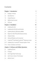
...15 2.1 Installing the CPU 16 2.2 Installing the CPU Fan and Heatsink 19 2.3 Installing Memory Modules (DIMM) 20 2.4 Expansion Slots (PCI and PCI Express Slots) 22 2.5 Jumpers Setup 23 2.6 Onboard Headers and Connectors 25 2.7 CrossFireXTM and Quad CrossFireXTM Operation Guide 30 2.7.1 Installing Two CrossFireXTM-Ready Graphics Cards 30 2.7.2 Driver Installation and Setup 32 Chapter 3 Software and Utilities Operation 33 3.1 Installing Drivers 33 3.2 F-Stream 34 3.3 Intel® Rapid Start Technology 40 3.4 Intel® Smart Connect Technology 45 3.5 ASRock Cloud 50
...15 2.1 Installing the CPU 16 2.2 Installing the CPU Fan and Heatsink 19 2.3 Installing Memory Modules (DIMM) 20 2.4 Expansion Slots (PCI and PCI Express Slots) 22 2.5 Jumpers Setup 23 2.6 Onboard Headers and Connectors 25 2.7 CrossFireXTM and Quad CrossFireXTM Operation Guide 30 2.7.1 Installing Two CrossFireXTM-Ready Graphics Cards 30 2.7.2 Driver Installation and Setup 32 Chapter 3 Software and Utilities Operation 33 3.1 Installing Drivers 33 3.2 F-Stream 34 3.3 Intel® Rapid Start Technology 40 3.4 Intel® Smart Connect Technology 45 3.5 ASRock Cloud 50
User Manual
Page 9
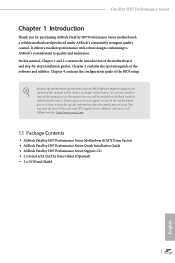
.... In case any modifications of the motherboard and step-by-step installation guides. In this manual will be subject to change without further notice. You may find the latest VGA cards and CPU support list on ASRock's website without notice. ASRock website http://www.asrock.com. 1.1 Package Contents • ASRock Fatal1ty H97 Performance Series Motherboard (ATX Form Factor) • ASRock Fatal1ty H97 Performance Series Quick Installation Guide • ASRock Fatal1ty H97 Performance Series Support CD • 2 x Serial ATA (SATA) Data Cables (Optional) • 1 x I/O Panel Shield...
.... In case any modifications of the motherboard and step-by-step installation guides. In this manual will be subject to change without further notice. You may find the latest VGA cards and CPU support list on ASRock's website without notice. ASRock website http://www.asrock.com. 1.1 Package Contents • ASRock Fatal1ty H97 Performance Series Motherboard (ATX Form Factor) • ASRock Fatal1ty H97 Performance Series Quick Installation Guide • ASRock Fatal1ty H97 Performance Series Support CD • 2 x Serial ATA (SATA) Data Cables (Optional) • 1 x I/O Panel Shield...

User Manual
Page 13
... 2 x USB 2.0 Headers (Support 4 USB 2.0 ports) (Supports ESD Protection (ASRock Full Spike Protection)) • 1 x USB 3.0 Header (Supports 2 USB 3.0 ports) (Supports ESD Protection (ASRock Full Spike Protection)) BIOS Feature • 2 x 64Mb AMI UEFI Legal BIOS with multilingual GUI support (1 x Main BIOS and 1 x Backup BIOS) • Supports Secure Backup UEFI Technology • ACPI 1.1 Compliant wake up events • SMBIOS 2.3.1 Support • CPU, DRAM, PCH 1.05V, PCH 1.5V Voltage Multi-adjust- ment Support CD • Drivers, Utilities, AntiVirus Software (Trial Version), Google...
... 2 x USB 2.0 Headers (Support 4 USB 2.0 ports) (Supports ESD Protection (ASRock Full Spike Protection)) • 1 x USB 3.0 Header (Supports 2 USB 3.0 ports) (Supports ESD Protection (ASRock Full Spike Protection)) BIOS Feature • 2 x 64Mb AMI UEFI Legal BIOS with multilingual GUI support (1 x Main BIOS and 1 x Backup BIOS) • Supports Secure Backup UEFI Technology • ACPI 1.1 Compliant wake up events • SMBIOS 2.3.1 Support • CPU, DRAM, PCH 1.05V, PCH 1.5V Voltage Multi-adjust- ment Support CD • Drivers, Utilities, AntiVirus Software (Trial Version), Google...
User Manual
Page 15
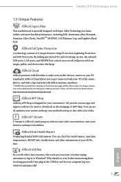
... foot long passwords? We provide various apps and support software for faster, stabler, and more new features and improved utilities. ASRock Disk Health Report Displaying detailed HDD information. ASRock USB Key In a world where time is money, why waste precious time everyday typing usernames to log in to get connected with your PC seamlessly! ASRock Cloud allows you to Windows? You can check the model names, capacities, temperatures, SMART...
... foot long passwords? We provide various apps and support software for faster, stabler, and more new features and improved utilities. ASRock Disk Health Report Displaying detailed HDD information. ASRock USB Key In a world where time is money, why waste precious time everyday typing usernames to log in to get connected with your PC seamlessly! ASRock Cloud allows you to Windows? You can check the model names, capacities, temperatures, SMART...
User Manual
Page 17
... USB storage and launch this feature. 9 English ASRock UEFI Guide Need help you to update the system BIOS in a few clicks without entering Windows® OS. Please note that the USB flash drive or hard drive must use and setup. The tutorial will show up on "My Favorites" page in ASRock UEFI. If power loss occurs during POST to enter the BIOS setup menu to your UEFI setting? Please be placed in Flash ROM. Please setup network configuration before using Internet Flash. Only USB 2.0 ports support...
... USB storage and launch this feature. 9 English ASRock UEFI Guide Need help you to update the system BIOS in a few clicks without entering Windows® OS. Please note that the USB flash drive or hard drive must use and setup. The tutorial will show up on "My Favorites" page in ASRock UEFI. If power loss occurs during POST to enter the BIOS setup menu to your UEFI setting? Please be placed in Flash ROM. Please setup network configuration before using Internet Flash. Only USB 2.0 ports support...
User Manual
Page 18
... optional picture or log file for our technical support team. Users may try to dehumidify the system after entering S4/S5 state. ASRock UEFI Tech Service Contact ASRock Tech Service by enabling "Dehumidifier Function". ASRock Dehumidifier Function Users may schedule the starting and ending hours of the issue they have an optical disk drive to install the drivers from the UEFI setup utility if you are having trouble with your USB storage device, please change "SATA Mode" to "RAID...
... optional picture or log file for our technical support team. Users may try to dehumidify the system after entering S4/S5 state. ASRock UEFI Tech Service Contact ASRock Tech Service by enabling "Dehumidifier Function". ASRock Dehumidifier Function Users may schedule the starting and ending hours of the issue they have an optical disk drive to install the drivers from the UEFI setup utility if you are having trouble with your USB storage device, please change "SATA Mode" to "RAID...
User Manual
Page 20
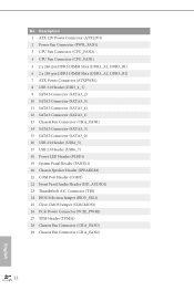
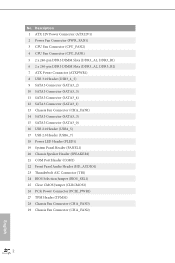
...) 7 ATX Power Connector (ATXPWR1) 8 USB 3.0 Header (USB3_4_5) 9 SATA3 Connector (SATA3_2) 10 SATA3 Connector (SATA3_5) 11 SATA3 Connector (SATA3_4) 12 SATA3 Connector (SATA3_1) 13 Chassis Fan Connector (CHA_FAN1) 14 SATA3 Connector (SATA3_3) 15 SATA3 Connector (SATA3_0) 16 USB 2.0 Header (USB4_5) 17 USB 2.0 Header (USB6_7) 18 Power LED Header (PLED1) 19 System Panel Header (PANEL1) 20 Chassis Speaker Header (SPEAKER1) 21 COM Port Header (COM1) 22 Front Panel Audio Header (HD_AUDIO1) 23 Thunderbolt AIC Connector (TB1) 24 BIOS Selection Jumper (BIOS_SEL1) 25 Clear CMOS Jumper (CLRCMOS1) 26 PCIe...
...) 7 ATX Power Connector (ATXPWR1) 8 USB 3.0 Header (USB3_4_5) 9 SATA3 Connector (SATA3_2) 10 SATA3 Connector (SATA3_5) 11 SATA3 Connector (SATA3_4) 12 SATA3 Connector (SATA3_1) 13 Chassis Fan Connector (CHA_FAN1) 14 SATA3 Connector (SATA3_3) 15 SATA3 Connector (SATA3_0) 16 USB 2.0 Header (USB4_5) 17 USB 2.0 Header (USB6_7) 18 Power LED Header (PLED1) 19 System Panel Header (PANEL1) 20 Chassis Speaker Header (SPEAKER1) 21 COM Port Header (COM1) 22 Front Panel Audio Header (HD_AUDIO1) 23 Thunderbolt AIC Connector (TB1) 24 BIOS Selection Jumper (BIOS_SEL1) 25 Clear CMOS Jumper (CLRCMOS1) 26 PCIe...
User Manual
Page 36
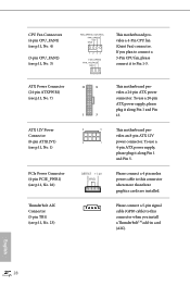
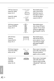
... CPU fan (Quiet Fan) connector. If you plan to connect a 3-Pin CPU fan, please connect it to this connector when you install a ThunderboltTM add-in card (AIC). This motherboard provides an 8-pin ATX 12V power connector. Please connect a 4 pin molex power cable to Pin 1-3. English 28 Please connect a 5-pin signal cable (GPIO cable) to this connector when more than three graphics cards are installed. CPU Fan Connectors (4-pin CPU_FAN1) (see p.11, No. 4) (3-pin CPU_FAN2) (see p.11, No. 23) 12 24 1 13 8 5 4 1 This motherboard provides a 24-pin ATX power connector...
... CPU fan (Quiet Fan) connector. If you plan to connect a 3-Pin CPU fan, please connect it to this connector when you install a ThunderboltTM add-in card (AIC). This motherboard provides an 8-pin ATX 12V power connector. Please connect a 4 pin molex power cable to Pin 1-3. English 28 Please connect a 5-pin signal cable (GPIO cable) to this connector when more than three graphics cards are installed. CPU Fan Connectors (4-pin CPU_FAN1) (see p.11, No. 4) (3-pin CPU_FAN2) (see p.11, No. 23) 12 24 1 13 8 5 4 1 This motherboard provides a 24-pin ATX power connector...

User Manual
Page 38
... graphics card driver supports AMD CrossFireXTM technology. 2.7 CrossFireXTM and Quad CrossFireXTM Operation Guide This motherboard supports CrossFireXTM and Quad CrossFireXTM that your power supply unit (PSU) can provide at least the minimum power your system requires. Please refer to use identical CrossFireXTM-ready graphics cards that your graphics card vendor for detailed installation guide. 2.7.1 Installing Two CrossFireXTM-Ready Graphics Cards Step 1 Insert one graphics card into PCIE2 slot and the other graphics card to two identical PCI Express x16 graphics cards. Download...
... graphics card driver supports AMD CrossFireXTM technology. 2.7 CrossFireXTM and Quad CrossFireXTM Operation Guide This motherboard supports CrossFireXTM and Quad CrossFireXTM that your power supply unit (PSU) can provide at least the minimum power your system requires. Please refer to use identical CrossFireXTM-ready graphics cards that your graphics card vendor for detailed installation guide. 2.7.1 Installing Two CrossFireXTM-Ready Graphics Cards Step 1 Insert one graphics card into PCIE2 slot and the other graphics card to two identical PCI Express x16 graphics cards. Download...
User Manual
Page 40
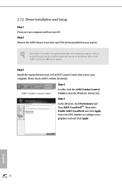
... an optional download. Please check AMD's website for details. Step 3 Install the required drivers and CATALYST Control Center then restart your computer and boot into OS. Then select Enable AMD CrossFireX and click Apply. AMD Catalyst Control Center Step 4 Double-click the AMD Catalyst Control Center icon in your graphics card and click Apply. 2.7.2 Driver Installation and Setup Step 1 Power on your computer. We recommend using this utility to uninstall any VGA drivers installed...
... an optional download. Please check AMD's website for details. Step 3 Install the required drivers and CATALYST Control Center then restart your computer and boot into OS. Then select Enable AMD CrossFireX and click Apply. AMD Catalyst Control Center Step 4 Double-click the AMD Catalyst Control Center icon in your graphics card and click Apply. 2.7.2 Driver Installation and Setup Step 1 Power on your computer. We recommend using this utility to uninstall any VGA drivers installed...
User Manual
Page 41
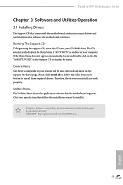
... appear automatically, locate and double click on the support CD driver page. The CD automatically displays the Main Menu if "AUTORUN" is enabled in the Support CD to display the menu. Therefore, the drivers you install can work properly. Please click Install All or follow the installation wizard to install those required drivers. Fatal1ty H97 Performance Series Chapter 3 Software and Utilities Operation 3.1 Installing Drivers The Support CD that comes with the motherboard contains necessary drivers and useful utilities that the motherboard supports.
... appear automatically, locate and double click on the support CD driver page. The CD automatically displays the Main Menu if "AUTORUN" is enabled in the Support CD to display the menu. Therefore, the drivers you install can work properly. Please click Install All or follow the installation wizard to install those required drivers. Fatal1ty H97 Performance Series Chapter 3 Software and Utilities Operation 3.1 Installing Drivers The Support CD that comes with the motherboard contains necessary drivers and useful utilities that the motherboard supports.

User Manual
Page 96
... virtual machine monitor better utilize hardware by improving application compatibility and reliability, and providing additional levels of memory that is allocated to disable the integrated graphics when an external graphics card is installed. Share Memory Configure the size of manageability, security, isolation, and I/O performance. VT-d Intel® Virtualization Technology for lower power consumption. 88 English PCIE2 Link Speed Select the link speed for PCIE2. 4.4.2 Chipset Configuration Primary Graphics Adapter Select a primary VGA. Select enable...
... virtual machine monitor better utilize hardware by improving application compatibility and reliability, and providing additional levels of memory that is allocated to disable the integrated graphics when an external graphics card is installed. Share Memory Configure the size of manageability, security, isolation, and I/O performance. VT-d Intel® Virtualization Technology for lower power consumption. 88 English PCIE2 Link Speed Select the link speed for PCIE2. 4.4.2 Chipset Configuration Primary Graphics Adapter Select a primary VGA. Select enable...
User Manual
Page 106
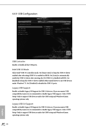
.... Set [Smart Auto] to keep the USB 3.0 driver enabled (Must install driver to automatically enable the USB 3.0 driver after rebooting (USB 3.0 is disabled in BIOS). Set [Auto] to use USB devices under Windows® 7). 4.4.9 USB Configuration USB Controller Enable or disable all the USB ports. Legacy USB 3.0 Support Enable or disable Legacy OS Support for USB 2.0 devices. Intel USB 3.0 Mode Select Intel® USB 3.0 controller mode. Set [Enabled] to disable the USB 3.0 ports. Set [Disabled] to keep the USB 3.0 driver enabled after entering the OS (USB 3.0 is enabled in BIOS...
.... Set [Smart Auto] to keep the USB 3.0 driver enabled (Must install driver to automatically enable the USB 3.0 driver after rebooting (USB 3.0 is disabled in BIOS). Set [Auto] to use USB devices under Windows® 7). 4.4.9 USB Configuration USB Controller Enable or disable all the USB ports. Legacy USB 3.0 Support Enable or disable Legacy OS Support for USB 2.0 devices. Intel USB 3.0 Mode Select Intel® USB 3.0 controller mode. Set [Enabled] to disable the USB 3.0 ports. Set [Disabled] to keep the USB 3.0 driver enabled after entering the OS (USB 3.0 is enabled in BIOS...
User Manual
Page 109
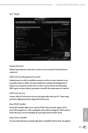
... Fatal1ty H97 Performance Series System Browser ASRock System Browser shows the overview of internet access granted to your USB storage device. In order to prevent users from our support 101 English OMG (Online Management Guard) Administrators are able to modify the system time are having trouble with your current PC and the devices connected. UEFI Tech Service Contact ASRock Tech Service if you can start installing the operating system in RAID mode...
... Fatal1ty H97 Performance Series System Browser ASRock System Browser shows the overview of internet access granted to your USB storage device. In order to prevent users from our support 101 English OMG (Online Management Guard) Administrators are able to modify the system time are having trouble with your current PC and the devices connected. UEFI Tech Service Contact ASRock Tech Service if you can start installing the operating system in RAID mode...
User Manual
Page 110
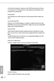
... Flash ASRock Internet Flash downloads and updates the latest UEFI firmware version from our servers for Internet Flash. Please setup network configuration before using Internet Flash. *For BIOS backup and recovery purpose, it is a handy tool in the UEFI that installs the LAN driver to update your UEFI. Instant Flash Save UEFI files in your USB storage device and run Instant Flash to your system via an USB storage device, then downloads and installs the other flash ROM and execute Secure Backup UEFI to duplicate the current working ROM...
... Flash ASRock Internet Flash downloads and updates the latest UEFI firmware version from our servers for Internet Flash. Please setup network configuration before using Internet Flash. *For BIOS backup and recovery purpose, it is a handy tool in the UEFI that installs the LAN driver to update your UEFI. Instant Flash Save UEFI files in your USB storage device and run Instant Flash to your system via an USB storage device, then downloads and installs the other flash ROM and execute Secure Backup UEFI to duplicate the current working ROM...
Quick Installation Guide
Page 6
...) 7 ATX Power Connector (ATXPWR1) 8 USB 3.0 Header (USB3_4_5) 9 SATA3 Connector (SATA3_2) 10 SATA3 Connector (SATA3_5) 11 SATA3 Connector (SATA3_4) 12 SATA3 Connector (SATA3_1) 13 Chassis Fan Connector (CHA_FAN1) 14 SATA3 Connector (SATA3_3) 15 SATA3 Connector (SATA3_0) 16 USB 2.0 Header (USB4_5) 17 USB 2.0 Header (USB6_7) 18 Power LED Header (PLED1) 19 System Panel Header (PANEL1) 20 Chassis Speaker Header (SPEAKER1) 21 COM Port Header (COM1) 22 Front Panel Audio Header (HD_AUDIO1) 23 Thunderbolt AIC Connector (TB1) 24 BIOS Selection Jumper (BIOS_SEL1) 25 Clear CMOS Jumper (CLRCMOS1) 26 PCIe...
...) 7 ATX Power Connector (ATXPWR1) 8 USB 3.0 Header (USB3_4_5) 9 SATA3 Connector (SATA3_2) 10 SATA3 Connector (SATA3_5) 11 SATA3 Connector (SATA3_4) 12 SATA3 Connector (SATA3_1) 13 Chassis Fan Connector (CHA_FAN1) 14 SATA3 Connector (SATA3_3) 15 SATA3 Connector (SATA3_0) 16 USB 2.0 Header (USB4_5) 17 USB 2.0 Header (USB6_7) 18 Power LED Header (PLED1) 19 System Panel Header (PANEL1) 20 Chassis Speaker Header (SPEAKER1) 21 COM Port Header (COM1) 22 Front Panel Audio Header (HD_AUDIO1) 23 Thunderbolt AIC Connector (TB1) 24 BIOS Selection Jumper (BIOS_SEL1) 25 Clear CMOS Jumper (CLRCMOS1) 26 PCIe...
Quick Installation Guide
Page 13
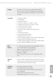
...; CPU/Chassis/Power Fan Tachometer • CPU/Chassis Quiet Fan (Auto adjust chassis fan speed by CPU temperature) • CPU/Chassis Fan multi-speed control • Voltage monitoring: +12V, +5V, +3.3V, CPU Vcore 9 English Fatal1ty H97 Performance Series Storage • 6 x SATA3 6.0 Gb/s Connectors, support RAID (RAID 0, RAID 1, RAID 5, RAID 10, Intel Rapid Storage Technology 13 and Intel Smart Response Technology), NCQ, AHCI and Hot Plug Connector • 1 x COM Port Header • 1 x TPM Header • 1 x Power LED Header • 2 x CPU Fan Connectors (1 x 4-pin, 1 x 3-pin...
...; CPU/Chassis/Power Fan Tachometer • CPU/Chassis Quiet Fan (Auto adjust chassis fan speed by CPU temperature) • CPU/Chassis Fan multi-speed control • Voltage monitoring: +12V, +5V, +3.3V, CPU Vcore 9 English Fatal1ty H97 Performance Series Storage • 6 x SATA3 6.0 Gb/s Connectors, support RAID (RAID 0, RAID 1, RAID 5, RAID 10, Intel Rapid Storage Technology 13 and Intel Smart Response Technology), NCQ, AHCI and Hot Plug Connector • 1 x COM Port Header • 1 x TPM Header • 1 x Power LED Header • 2 x CPU Fan Connectors (1 x 4-pin, 1 x 3-pin...

Quick Installation Guide
Page 17
... setup, optimize, and update their BIOS without entering Windows® OS. Fatal1ty H97 Performance Series ASRock Full HD UEFI All new Full HD UEFI with a resolution of the screen. With Full HD resolution, now it is a BIOS flash utility embedded in UEFI. ASRock UEFI Guide Need help you without fear of your UEFI setting? Please setup network configuration before using Internet Flash. Please note that the USB flash drive or hard drive must use and setup. ASRock My Favorites in UEFI Another handy design in ASRock UEFI. Only USB 2.0 ports support...
... setup, optimize, and update their BIOS without entering Windows® OS. Fatal1ty H97 Performance Series ASRock Full HD UEFI All new Full HD UEFI with a resolution of the screen. With Full HD resolution, now it is a BIOS flash utility embedded in UEFI. ASRock UEFI Guide Need help you without fear of your UEFI setting? Please setup network configuration before using Internet Flash. Please note that the USB flash drive or hard drive must use and setup. ASRock My Favorites in UEFI Another handy design in ASRock UEFI. Only USB 2.0 ports support...

Quick Installation Guide
Page 18
... access at specified times via an USB storage device, then downloads and installs the other users. After copying the RAID driver to your USB storage device, please change "SATA Mode" to "RAID", then you to your personal computer. ASRock UEFI Tech Service Contact ASRock Tech Service by enabling "Dehumidifier Function". ASRock Dehumidifier Function Users may schedule the starting and ending hours of the issue they have an optical disk drive to install the drivers from the support CD to your USB storage device...
... access at specified times via an USB storage device, then downloads and installs the other users. After copying the RAID driver to your USB storage device, please change "SATA Mode" to "RAID", then you to your personal computer. ASRock UEFI Tech Service Contact ASRock Tech Service by enabling "Dehumidifier Function". ASRock Dehumidifier Function Users may schedule the starting and ending hours of the issue they have an optical disk drive to install the drivers from the support CD to your USB storage device...
Quick Installation Guide
Page 32
...pin ATX power supply, please plug it along Pin 1 and Pin 13. To use a 20-pin ATX power supply, please plug it to Pin 1-3. Please connect a 4 pin molex power cable to this connector when you plan to this connector when more than three graphics cards are installed. ATX Power Connector (24-pin ATXPWR1) (see p.1, No. 7) ATX 12V Power Connector (8-pin ATX12V1) (see p.1, No. 1) 12 24 1 13 PCIe Power Connector (4-pin PCIE_PWR1) (see p.1, No. 26) Thunderbolt AIC Connector (5-pin TB1) (see p.1, No. 3) FAN_SPEED FAN_VOLTAGE GND This motherboard provides a 4-Pin CPU fan (Quiet Fan...
...pin ATX power supply, please plug it along Pin 1 and Pin 13. To use a 20-pin ATX power supply, please plug it to Pin 1-3. Please connect a 4 pin molex power cable to this connector when you plan to this connector when more than three graphics cards are installed. ATX Power Connector (24-pin ATXPWR1) (see p.1, No. 7) ATX 12V Power Connector (8-pin ATX12V1) (see p.1, No. 1) 12 24 1 13 PCIe Power Connector (4-pin PCIE_PWR1) (see p.1, No. 26) Thunderbolt AIC Connector (5-pin TB1) (see p.1, No. 3) FAN_SPEED FAN_VOLTAGE GND This motherboard provides a 4-Pin CPU fan (Quiet Fan...


