User Manual
Page 6
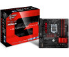
... Contents 1 1.2 Specifications 2 1.3 Motherboard Layout 7 1.4 I/O Panel 9 Chapter 2 Installation 11 2.1 Installing the CPU 12 2.2 Installing the CPU Fan and Heatsink 15 2.3 Installing Memory Modules (DIMM) 16 2.4 Expansion Slots (PCI Express Slots) 18 2.5 Onboard Headers and Connectors 19 2.6 CrossFireXTM and Quad CrossFireXTM Operation Guide 24 2.6.1 Installing Two CrossFireXTM-Ready Graphics Cards 24 2.6.2 Driver Installation and Setup 26 2.7 M.2_SSD (NGFF) Module Installation Guide 27 Chapter 3 Software and Utilities Operation 30 3.1 Installing Drivers 30...
... Contents 1 1.2 Specifications 2 1.3 Motherboard Layout 7 1.4 I/O Panel 9 Chapter 2 Installation 11 2.1 Installing the CPU 12 2.2 Installing the CPU Fan and Heatsink 15 2.3 Installing Memory Modules (DIMM) 16 2.4 Expansion Slots (PCI Express Slots) 18 2.5 Onboard Headers and Connectors 19 2.6 CrossFireXTM and Quad CrossFireXTM Operation Guide 24 2.6.1 Installing Two CrossFireXTM-Ready Graphics Cards 24 2.6.2 Driver Installation and Setup 26 2.7 M.2_SSD (NGFF) Module Installation Guide 27 Chapter 3 Software and Utilities Operation 30 3.1 Installing Drivers 30...
User Manual
Page 7
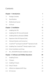
...35 3.3.3 BIOS & Drivers 38 3.3.4 Setting 39 3.4 Creative SoundBlaster Cinema3 40 3.5 Enabling USB Ports for Windows® 7 Installation 41 3.6 ASRock AURA RGB LED 44 Chapter 4 UEFI SETUP UTILITY 45 4.1 Introduction 45 4.2 EZ Mode 46 4.3 Advanced Mode 47 4.3.1 UEFI Menu Bar 47 4.3.2 Navigation Keys 48 4.4 Main Screen 49 4.5 OC Tweaker Screen 50 4.6 Advanced Screen 56 4.6.1 CPU Configuration 57 4.6.2 Chipset Configuration 59 4.6.3 Storage Configuration 62 4.6.4 Super IO Configuration 63 4.6.5 ACPI Configuration 64 4.6.6 USB Configuration 66 4.6.7 Trusted...
...35 3.3.3 BIOS & Drivers 38 3.3.4 Setting 39 3.4 Creative SoundBlaster Cinema3 40 3.5 Enabling USB Ports for Windows® 7 Installation 41 3.6 ASRock AURA RGB LED 44 Chapter 4 UEFI SETUP UTILITY 45 4.1 Introduction 45 4.2 EZ Mode 46 4.3 Advanced Mode 47 4.3.1 UEFI Menu Bar 47 4.3.2 Navigation Keys 48 4.4 Main Screen 49 4.5 OC Tweaker Screen 50 4.6 Advanced Screen 56 4.6.1 CPU Configuration 57 4.6.2 Chipset Configuration 59 4.6.3 Storage Configuration 62 4.6.4 Super IO Configuration 63 4.6.5 ACPI Configuration 64 4.6.6 USB Configuration 66 4.6.7 Trusted...

User Manual
Page 9
... ASRock's commitment to change without further notice. In case any modifications of the software and utilities. Fatal1ty H270M Performance Series Chapter 1 Introduction Thank you are using. If you require technical support related to this documentation occur, the updated version will be available on ASRock's website as well. Chapter 3 contains the operation guide of this motherboard, please visit our website for specific information about the model you for M.2 Sockets (Optional) • 1 x I/O Panel...
... ASRock's commitment to change without further notice. In case any modifications of the software and utilities. Fatal1ty H270M Performance Series Chapter 1 Introduction Thank you are using. If you require technical support related to this documentation occur, the updated version will be available on ASRock's website as well. Chapter 3 contains the operation guide of this motherboard, please visit our website for specific information about the model you for M.2 Sockets (Optional) • 1 x I/O Panel...
User Manual
Page 11
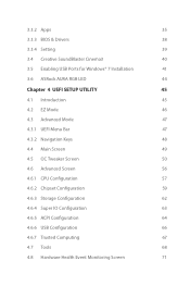
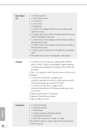
... • Supports DVI-D with max. resolution up to use an HD front panel audio module and enable the multi-channel audio feature through the audio driver. • Premium Blu-ray Audio support • Supports Surge Protection (ASRock Full Spike Protection) • Nichicon Fine Gold Series Audio Caps • Supports Creative SoundBlaster Cinema3 • Gigabit LAN 10/100/1000 Mb/s • Giga PHY Intel® I219V • Supports Wake-On-LAN • Supports Lightning...
... • Supports DVI-D with max. resolution up to use an HD front panel audio module and enable the multi-channel audio feature through the audio driver. • Premium Blu-ray Audio support • Supports Surge Protection (ASRock Full Spike Protection) • Nichicon Fine Gold Series Audio Caps • Supports Creative SoundBlaster Cinema3 • Gigabit LAN 10/100/1000 Mb/s • Giga PHY Intel® I219V • Supports Wake-On-LAN • Supports Lightning...
User Manual
Page 12
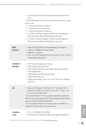
...; 3 x USB 3.0 Type-A Ports (Supports ESD Protection (ASRock Full Spike Protection)) • 1 x USB 3.0 Type-C Port (Supports ESD Protection (ASRock Full Spike Protection)) • 1 x RJ-45 LAN Port with LED (ACT/LINK LED and SPEED LED) • HD Audio Jacks: Line in / Front Speaker / Microphone Storage • 6 x SATA3 6.0 Gb/s Connectors, support RAID (RAID 0, RAID 1, RAID 5, RAID 10, Intel Rapid Storage Technology 15 and Intel Smart Response Technology), NCQ, AHCI and Hot Plug* * If M2_1 is occupied by a SATA-type M.2 device, SATA3_0 will be disabled. • 1 x Ultra M.2 Socket (M2_1...
...; 3 x USB 3.0 Type-A Ports (Supports ESD Protection (ASRock Full Spike Protection)) • 1 x USB 3.0 Type-C Port (Supports ESD Protection (ASRock Full Spike Protection)) • 1 x RJ-45 LAN Port with LED (ACT/LINK LED and SPEED LED) • HD Audio Jacks: Line in / Front Speaker / Microphone Storage • 6 x SATA3 6.0 Gb/s Connectors, support RAID (RAID 0, RAID 1, RAID 5, RAID 10, Intel Rapid Storage Technology 15 and Intel Smart Response Technology), NCQ, AHCI and Hot Plug* * If M2_1 is occupied by a SATA-type M.2 device, SATA3_0 will be disabled. • 1 x Ultra M.2 Socket (M2_1...
User Manual
Page 13
... pin ATX Power Connector • 1 x 8 pin 12V Power Connector • 1 x Front Panel Audio Connector • 2 x USB 2.0 Headers (Support 4 USB 2.0 ports) (Supports ESD Protection (ASRock Full Spike Protection)) • 2 x USB 3.0 Headers (Support 4 USB 3.0 ports) (Supports ESD Protection (ASRock Full Spike Protection)) BIOS Feature • AMI UEFI Legal BIOS with multilingual GUI support • ACPI 6.0 Compliant wake up events • SMBIOS 2.7 Support • CPU, GT_CPU, DRAM, PCH 1.0V, VCCIO, VCCSA, VCCST Voltage Multi-adjustment Hardware Monitor • CPU/Chassis temperature...
... pin ATX Power Connector • 1 x 8 pin 12V Power Connector • 1 x Front Panel Audio Connector • 2 x USB 2.0 Headers (Support 4 USB 2.0 ports) (Supports ESD Protection (ASRock Full Spike Protection)) • 2 x USB 3.0 Headers (Support 4 USB 3.0 ports) (Supports ESD Protection (ASRock Full Spike Protection)) BIOS Feature • AMI UEFI Legal BIOS with multilingual GUI support • ACPI 6.0 Compliant wake up events • SMBIOS 2.7 Support • CPU, GT_CPU, DRAM, PCH 1.0V, VCCIO, VCCSA, VCCST Voltage Multi-adjustment Hardware Monitor • CPU/Chassis temperature...
User Manual
Page 16
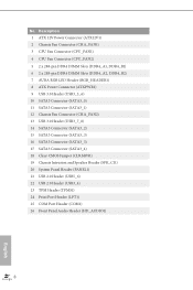
...) 3 CPU Fan Connector (CPU_FAN1) 4 CPU Fan Connector (CPU_FAN2) 5 2 x 288-pin DDR4 DIMM Slots (DDR4_A1, DDR4_B1) 6 2 x 288-pin DDR4 DIMM Slots (DDR4_A2, DDR4_B2) 7 AURA RGB LED Header (RGB_HEADER1) 8 ATX Power Connector (ATXPWR1) 9 USB 3.0 Header (USB3_5_6) 10 SATA3 Connector (SATA3_0) 11 SATA3 Connector (SATA3_1) 12 Chassis Fan Connector (CHA_FAN2) 13 USB 3.0 Header (USB3_7_8) 14 SATA3 Connector (SATA3_2) 15 SATA3 Connector (SATA3_3) 16 SATA3 Connector (SATA3_5) 17 SATA3 Connector (SATA3_4) 18 Clear CMOS Jumper (CLRMOS1) 19 Chassis Intrusion and Speaker Header (SPK_CI1) 20 System Panel Header...
...) 3 CPU Fan Connector (CPU_FAN1) 4 CPU Fan Connector (CPU_FAN2) 5 2 x 288-pin DDR4 DIMM Slots (DDR4_A1, DDR4_B1) 6 2 x 288-pin DDR4 DIMM Slots (DDR4_A2, DDR4_B2) 7 AURA RGB LED Header (RGB_HEADER1) 8 ATX Power Connector (ATXPWR1) 9 USB 3.0 Header (USB3_5_6) 10 SATA3 Connector (SATA3_0) 11 SATA3 Connector (SATA3_1) 12 Chassis Fan Connector (CHA_FAN2) 13 USB 3.0 Header (USB3_7_8) 14 SATA3 Connector (SATA3_2) 15 SATA3 Connector (SATA3_3) 16 SATA3 Connector (SATA3_5) 17 SATA3 Connector (SATA3_4) 18 Clear CMOS Jumper (CLRMOS1) 19 Chassis Intrusion and Speaker Header (SPK_CI1) 20 System Panel Header...
User Manual
Page 26
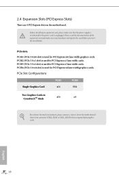
... connect a chassis fan to the motherboard's chassis fan connector (CHA_FAN1 or CHA_FAN2) when using multiple graphics cards. PCIE3 (PCIe 3.0 x1 slot) is used for PCI Express x16 lane width graphics cards. PCIe slots: PCIE1 (PCIe 3.0 x16 slot) is used for PCI Express x1 lane width cards. PCIE2 (PCIe 3.0 x1 slot) is used for PCI Express x4 lane width graphics cards. Please read the documentation of the expansion card and make sure that the power supply is switched off or the power cord is used for the card before you start...
... connect a chassis fan to the motherboard's chassis fan connector (CHA_FAN1 or CHA_FAN2) when using multiple graphics cards. PCIE3 (PCIe 3.0 x1 slot) is used for PCI Express x16 lane width graphics cards. PCIe slots: PCIE1 (PCIe 3.0 x16 slot) is used for PCI Express x1 lane width cards. PCIE2 (PCIe 3.0 x1 slot) is used for PCI Express x4 lane width graphics cards. Please read the documentation of the expansion card and make sure that the power supply is switched off or the power cord is used for the card before you start...
User Manual
Page 27
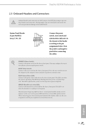
... wire assignments and the pin assignments are NOT jumpers. PLED (System Power LED): Connect to the hard drive activity LED on the chassis front panel. The LED is on when the system is in S1/S3 sleep state. The front panel design may configure the way to turn off (S5). A front panel module mainly consists of power switch, reset switch, power LED, hard drive activity LED, speaker and etc. Note the positive and negative pins before connecting the cables. Fatal1ty H270M Performance Series 2.5 Onboard Headers and Connectors Onboard headers and connectors...
... wire assignments and the pin assignments are NOT jumpers. PLED (System Power LED): Connect to the hard drive activity LED on the chassis front panel. The LED is on when the system is in S1/S3 sleep state. The front panel design may configure the way to turn off (S5). A front panel module mainly consists of power switch, reset switch, power LED, hard drive activity LED, speaker and etc. Note the positive and negative pins before connecting the cables. Fatal1ty H270M Performance Series 2.5 Onboard Headers and Connectors Onboard headers and connectors...
User Manual
Page 29
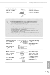
..." Tab in our manual and chassis manual to the ground pin. C. FAN_VOLTAGE_CONTROL GND FAN_SPEED_CONTROL vides a 4-Pin CPU fan (Quiet Fan) connector. Please follow the instructions in the Realtek Control panel and adjust "Recording Volume". MIC_RET and OUT_RET are for the AC'97 audio panel. Connect Ground (GND) to MIC2_L. If you plan to connect a FAN_SPEED FAN_VOLTAGE GND 3-Pin CPU fan, please connect it to the front audio panel. 1. Fatal1ty H270M Performance Series Front Panel Audio Header (9-pin HD_AUDIO1) (see p.7, No...
..." Tab in our manual and chassis manual to the ground pin. C. FAN_VOLTAGE_CONTROL GND FAN_SPEED_CONTROL vides a 4-Pin CPU fan (Quiet Fan) connector. Please follow the instructions in the Realtek Control panel and adjust "Recording Volume". MIC_RET and OUT_RET are for the AC'97 audio panel. Connect Ground (GND) to MIC2_L. If you plan to connect a FAN_SPEED FAN_VOLTAGE GND 3-Pin CPU fan, please connect it to the front audio panel. 1. Fatal1ty H270M Performance Series Front Panel Audio Header (9-pin HD_AUDIO1) (see p.7, No...

User Manual
Page 31
Caution: Never install the RGB LED cable in the wrong orientation; otherwise, the cable may be damaged. AURA RGB LED Header (4-pin RGB_HEADER1) (see p.7, No. 7) Fatal1ty H270M Performance Series AURA RGB LED header is used to connect RGB LED extension cable which allows users to choose from various LED lighting effects. English 23
Caution: Never install the RGB LED cable in the wrong orientation; otherwise, the cable may be damaged. AURA RGB LED Header (4-pin RGB_HEADER1) (see p.7, No. 7) Fatal1ty H270M Performance Series AURA RGB LED header is used to connect RGB LED extension cable which allows users to choose from various LED lighting effects. English 23
User Manual
Page 32
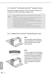
... power your graphics card driver supports AMD CrossFireXTM technology. Please refer to the AMD's website for detailed installation guide. 2.6.1 Installing Two CrossFireXTM-Ready Graphics Cards Step 1 Insert one graphics card into PCIE1 slot and the other graphics card to use a AMD certified PSU. If you to install up to AMD graphics card manuals for details. 4. CrossFire Bridge Step 2 Connect two graphics cards by installing a CrossFire Bridge on the CrossFire Bridge Interconnects on the slots. Please refer to three identical PCI Express x16 graphics cards...
... power your graphics card driver supports AMD CrossFireXTM technology. Please refer to the AMD's website for detailed installation guide. 2.6.1 Installing Two CrossFireXTM-Ready Graphics Cards Step 1 Insert one graphics card into PCIE1 slot and the other graphics card to use a AMD certified PSU. If you to install up to AMD graphics card manuals for details. 4. CrossFire Bridge Step 2 Connect two graphics cards by installing a CrossFire Bridge on the CrossFire Bridge Interconnects on the slots. Please refer to three identical PCI Express x16 graphics cards...
User Manual
Page 34
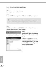
... graphics card and click Apply. Please check AMD's website for AMD driver updates. Step 5 In the left pane, click Performance and then AMD CrossFireXTM. English 26 Step 2 Remove the AMD drivers if you have any previously installed Catalyst drivers prior to uninstall any VGA drivers installed in the Windows® system tray. The Catalyst Uninstaller is an optional download. 2.6.2 Driver Installation and Setup Step 1 Power on your system. We recommend using this utility to installation. AMD Catalyst Control...
... graphics card and click Apply. Please check AMD's website for AMD driver updates. Step 5 In the left pane, click Performance and then AMD CrossFireXTM. English 26 Step 2 Remove the AMD drivers if you have any previously installed Catalyst drivers prior to uninstall any VGA drivers installed in the Windows® system tray. The Catalyst Uninstaller is an optional download. 2.6.2 Driver Installation and Setup Step 1 Power on your system. We recommend using this utility to installation. AMD Catalyst Control...
User Manual
Page 38
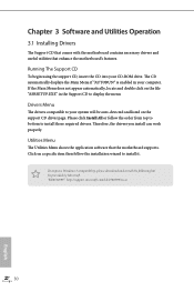
... the motherboard contains necessary drivers and useful utilities that the motherboard supports. Please click Install All or follow the installation wizard to install it. If the Main Menu does not appear automatically, locate and double click on the support CD driver page. Therefore, the drivers you install can work properly. Drivers Menu The drivers compatible to your system will be auto-detected and listed on the file "ASRSETUP.EXE" in your CD-ROM drive. Running The Support...
... the motherboard contains necessary drivers and useful utilities that the motherboard supports. Please click Install All or follow the installation wizard to install it. If the Main Menu does not appear automatically, locate and double click on the support CD driver page. Therefore, the drivers you install can work properly. Drivers Menu The drivers compatible to your system will be auto-detected and listed on the file "ASRSETUP.EXE" in your CD-ROM drive. Running The Support...
User Manual
Page 49
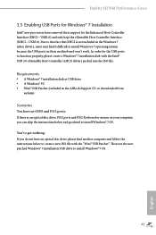
... the Intel® USB 3.0 eXtensible Host Controller (xHCI) drivers packed into the ISO file. You've got nothing: If you can skip the instructions below to install Windows® 7 OS. USB3.0). Fatal1ty H270M Performance Series 3.5 Enabling USB Ports for Windows® 7 Installation Intel® new processors have removed their motherboard won't work. Then use the new patched Windows® 7 installation USB drive to function properly, please create a Windows® 7 installation disk with the "Win7 USB Patcher". USB2.0) and only...
... the Intel® USB 3.0 eXtensible Host Controller (xHCI) drivers packed into the ISO file. You've got nothing: If you can skip the instructions below to install Windows® 7 OS. USB3.0). Fatal1ty H270M Performance Series 3.5 Enabling USB Ports for Windows® 7 Installation Intel® new processors have removed their motherboard won't work. Then use the new patched Windows® 7 installation USB drive to function properly, please create a Windows® 7 installation disk with the "Win7 USB Patcher". USB2.0) and only...
User Manual
Page 68
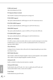
... graphics processor when the system boots up. Share Memory Configure the size of the DMI Link. IGPU Multi-Monitor Select disable to one or more local APICs. Set to Auto to enable onboard HD audio and automatically disable it receives from peripheral buses to disable the integrated graphics when an external graphics card is installed. PCI Express Native Control Select Enable for PCIE4. PCIE ASPM Support This option enables/disables the ASPM support for all times. Front Panel Enable/disable front panel HD audio...
... graphics processor when the system boots up. Share Memory Configure the size of the DMI Link. IGPU Multi-Monitor Select disable to one or more local APICs. Set to Auto to enable onboard HD audio and automatically disable it receives from peripheral buses to disable the integrated graphics when an external graphics card is installed. PCI Express Native Control Select Enable for PCIE4. PCIE ASPM Support This option enables/disables the ASPM support for all times. Front Panel Enable/disable front panel HD audio...
User Manual
Page 76
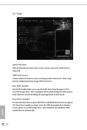
... drivers please change the SATA mode to your USB storage device. Please setup network configuration before using UEFI Tech Service. Easy Driver Installer For users that don't have an optical disk drive to install the drivers from the support CD to your system via an USB storage device, then downloads and installs the other required drivers automatically. 68 English UEFI Tech Service Contact ASRock Tech Service if you can start installing the operating system in the UEFI that installs the LAN driver to RAID, then you are having trouble...
... drivers please change the SATA mode to your USB storage device. Please setup network configuration before using UEFI Tech Service. Easy Driver Installer For users that don't have an optical disk drive to install the drivers from the support CD to your system via an USB storage device, then downloads and installs the other required drivers automatically. 68 English UEFI Tech Service Contact ASRock Tech Service if you can start installing the operating system in the UEFI that installs the LAN driver to RAID, then you are having trouble...
User Manual
Page 77
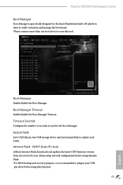
... using this tool. Boot Manager Enable/disable the Boot Manager. Internet Flash - Boot Manager Timeout Enable/disable the Boot Manager Timeout. Please setup network configuration before using Internet Flash. *For BIOS backup and recovery purpose, it is specifically designed for you. Instant Flash Save UEFI files in your UEFI. DHCP (Auto IP), Auto ASRock Internet Flash downloads and updates the latest UEFI firmware version from our servers for the dual OS platform/multi-OS platform users to easily customize and manage the boot menu. *Please connect...
... using this tool. Boot Manager Enable/disable the Boot Manager. Internet Flash - Boot Manager Timeout Enable/disable the Boot Manager Timeout. Please setup network configuration before using Internet Flash. *For BIOS backup and recovery purpose, it is specifically designed for you. Instant Flash Save UEFI files in your UEFI. DHCP (Auto IP), Auto ASRock Internet Flash downloads and updates the latest UEFI firmware version from our servers for the dual OS platform/multi-OS platform users to easily customize and manage the boot menu. *Please connect...
User Manual
Page 78
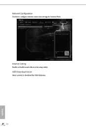
Network Configuration Use this to download the UEFI firmware. 70 English Internet Setting Enable or disable sound effects in the setup utility. UEFI Download Server Select a server to configure internet connection settings for Internet Flash.
Network Configuration Use this to download the UEFI firmware. 70 English Internet Setting Enable or disable sound effects in the setup utility. UEFI Download Server Select a server to configure internet connection settings for Internet Flash.
User Manual
Page 81
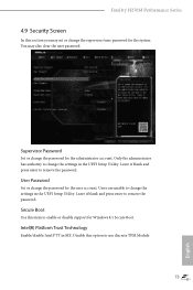
Fatal1ty H270M Performance Series 4.9 Security Screen In this item to enable or disable support for Windows 8.1 Secure Boot. Secure Boot Use this section you may also clear the user password. Intel(R) Platform Trust Technology Enable/disable Intel PTT in the UEFI Setup Utility. User Password Set or change the password for the administrator account. Users are unable to remove the password. You may set or change the settings in ME. Leave it blank and press enter to change the supervisor/user password for the system. Only the...
Fatal1ty H270M Performance Series 4.9 Security Screen In this item to enable or disable support for Windows 8.1 Secure Boot. Secure Boot Use this section you may also clear the user password. Intel(R) Platform Trust Technology Enable/disable Intel PTT in the UEFI Setup Utility. User Password Set or change the password for the administrator account. Users are unable to remove the password. You may set or change the settings in ME. Leave it blank and press enter to change the supervisor/user password for the system. Only the...


