
User Manual
Page 6
... 1 1.1 Package Contents 1 1.2 Specifications 2 1.3 Motherboard Layout 7 1.4 I/O Panel 9 Chapter 2 Installation 11 2.1 Installing the CPU 12 2.2 Installing the CPU Fan and Heatsink 14 2.3 Installing Memory Modules (DIMM) 23 2.4 Expansion Slots (PCI Express Slots) 26 2.5 Jumpers Setup 27 2.6 Onboard Headers and Connectors 28 2.7 CrossFireXTM and Quad CrossFireXTM Operation Guide 33 2.7.1 Installing Two CrossFireXTM-Ready Graphics Cards...
... 1 1.1 Package Contents 1 1.2 Specifications 2 1.3 Motherboard Layout 7 1.4 I/O Panel 9 Chapter 2 Installation 11 2.1 Installing the CPU 12 2.2 Installing the CPU Fan and Heatsink 14 2.3 Installing Memory Modules (DIMM) 23 2.4 Expansion Slots (PCI Express Slots) 26 2.5 Jumpers Setup 27 2.6 Onboard Headers and Connectors 28 2.7 CrossFireXTM and Quad CrossFireXTM Operation Guide 33 2.7.1 Installing Two CrossFireXTM-Ready Graphics Cards...
User Manual
Page 13
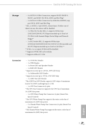
... 1A (12W) fan power. • 1 x CPU/Water Pump Fan Connector (4-pin) (Smart Fan Speed Control) * The CPU/Water Pump Fan supports the water cooler fan of maximum 2A (24W) fan power. • 3 x Chassis/Water Pump Fan Connectors (4-pin) (Smart Fan Speed Control) * The Chassis/Water Pump Fan supports the water cooler fan of maximum 2A (24W) fan power. Fatal1ty B450 Gaming K4 Series Storage •...
... 1A (12W) fan power. • 1 x CPU/Water Pump Fan Connector (4-pin) (Smart Fan Speed Control) * The CPU/Water Pump Fan supports the water cooler fan of maximum 2A (24W) fan power. • 3 x Chassis/Water Pump Fan Connectors (4-pin) (Smart Fan Speed Control) * The Chassis/Water Pump Fan supports the water cooler fan of maximum 2A (24W) fan power. Fatal1ty B450 Gaming K4 Series Storage •...

User Manual
Page 14
... 1 x 8 pin 12V Power Connector • 1 x Front Panel Audio Connector • 2 x USB 2.0 Headers (Support 4 USB 2.0 ports) (Supports ESD Protection) • 1 x USB 3.1 Gen1 Header (Supports 2 USB 3.1 Gen1 ports) (Supports ESD Protection) BIOS Feature • AMI UEFI Legal BIOS with multilingual GUI...Fans • Voltage monitoring: +12V, +5V, +3.3V, Vcore OS • Microsoft® Windows® 10 64-bit Certifications • FCC, CE • ErP/EuP ready (ErP/EuP ready power supply is required) English * For detailed product information, please visit our website: http://www.asrock...
... 1 x 8 pin 12V Power Connector • 1 x Front Panel Audio Connector • 2 x USB 2.0 Headers (Support 4 USB 2.0 ports) (Supports ESD Protection) • 1 x USB 3.1 Gen1 Header (Supports 2 USB 3.1 Gen1 ports) (Supports ESD Protection) BIOS Feature • AMI UEFI Legal BIOS with multilingual GUI...Fans • Voltage monitoring: +12V, +5V, +3.3V, Vcore OS • Microsoft® Windows® 10 64-bit Certifications • FCC, CE • ErP/EuP ready (ErP/EuP ready power supply is required) English * For detailed product information, please visit our website: http://www.asrock...

User Manual
Page 16
... System Panel Header (PANEL1) 17 Chassis Fan / Waterpump Fan Connector (CHA_FAN3/WP) 18 Chassis Fan / Waterpump Fan Connector (CHA_FAN2/WP) 19 Clear CMOS Jumper (CLRCMOS2) 20 Addressable LED Header (ADDR_LED1) 21 USB 2.0 Header (USB_3_4) 22 USB 2.0 Header (USB_1_2) 23 COM Port Header (COM1) 24 RGB LED Header (RGB_LED1) 25 TPM Header (TPMS1) 26 Front Panel Audio Header (HD_AUDIO1) 27 Chassis Fan / Waterpump Fan Connector...
... System Panel Header (PANEL1) 17 Chassis Fan / Waterpump Fan Connector (CHA_FAN3/WP) 18 Chassis Fan / Waterpump Fan Connector (CHA_FAN2/WP) 19 Clear CMOS Jumper (CLRCMOS2) 20 Addressable LED Header (ADDR_LED1) 21 USB 2.0 Header (USB_3_4) 22 USB 2.0 Header (USB_1_2) 23 COM Port Header (COM1) 24 RGB LED Header (RGB_LED1) 25 TPM Header (TPMS1) 26 Front Panel Audio Header (HD_AUDIO1) 27 Chassis Fan / Waterpump Fan Connector...

User Manual
Page 26
Please refer to page 32 for reference only. 4 CPU_FAN1 5 RGB LED Cable 4-pin FAN cable CPU_FAN1 +12V AMD_FAN_LED1 *The diagram shown here are for the orientation of AMD Fan LED Header (AMD_FAN_LED1). 18 English
Please refer to page 32 for reference only. 4 CPU_FAN1 5 RGB LED Cable 4-pin FAN cable CPU_FAN1 +12V AMD_FAN_LED1 *The diagram shown here are for the orientation of AMD Fan LED Header (AMD_FAN_LED1). 18 English

User Manual
Page 30
If you select USB connector, please install AMD utility "SR3 Settings Software". *The diagram shown here are for the orientation of AMD Fan LED Header (AMD_FAN_LED1). 22 English Please refer to page 32 for reference only. 6 CPU_FAN1 +12V AMD_FAN_LED1 or 7 CPU_FAN1 AMD_FAN_LED1 USB_5 Please note that only one cable should be used at a time in this step. If you select AMD_FAN_LED1, please install ASRock utility "ASRock Polychrome LED".
If you select USB connector, please install AMD utility "SR3 Settings Software". *The diagram shown here are for the orientation of AMD Fan LED Header (AMD_FAN_LED1). 22 English Please refer to page 32 for reference only. 6 CPU_FAN1 +12V AMD_FAN_LED1 or 7 CPU_FAN1 AMD_FAN_LED1 USB_5 Please note that only one cable should be used at a time in this step. If you select AMD_FAN_LED1, please install ASRock utility "ASRock Polychrome LED".

User Manual
Page 38
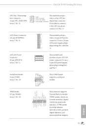
... No. 17) FAN_SPEED_CONTROL CHA_FAN_SPEED FAN_VOLTAGE GND CPU Fan Connector This motherboard pro- (4-pin CPU_FAN1) 1 2 GND FAN_VOLTAGE vides a 4-Pin CPU fan (see p.7, No. 26) GND PRESENCE# MIC_RET OUT_RET 1 OUT2_L J_SENSE OUT2_R MIC2_R MIC2_L This header is for the HD audio panel only. Connect... Ground (GND) to the front audio panel. 1. B. Front Panel Audio Header (9-pin HD_AUDIO1) (see p.7, No. 5) 3 CPU_FAN_SPEED (Quiet Fan) connector. 4 FAN_SPEED_CONTROL If you use an...
... No. 17) FAN_SPEED_CONTROL CHA_FAN_SPEED FAN_VOLTAGE GND CPU Fan Connector This motherboard pro- (4-pin CPU_FAN1) 1 2 GND FAN_VOLTAGE vides a 4-Pin CPU fan (see p.7, No. 26) GND PRESENCE# MIC_RET OUT_RET 1 OUT2_L J_SENSE OUT2_R MIC2_R MIC2_L This header is for the HD audio panel only. Connect... Ground (GND) to the front audio panel. 1. B. Front Panel Audio Header (9-pin HD_AUDIO1) (see p.7, No. 5) 3 CPU_FAN_SPEED (Quiet Fan) connector. 4 FAN_SPEED_CONTROL If you use an...
User Manual
Page 39
...ATX power connector. To use a 20-pin ATX power supply, please plug it along Pin 1 and Pin 5. Serial Port Header (9-pin COM1) (see p.7, No. 25) 1 PCICLK FRAME PCIRST# LAD3 +3V LAD0 +3VSB GND GND SMB_CLK_MAIN SMB_DATA_MAIN LAD2.... 31 English ATX 12V Power Connector (8-pin ATX12V1) (see p.7, No. 6) GND FAN_VOLTAGE This motherboard provides a 4-Pin CPU fan CPU_FAN_SPEED FAN_SPEED_CONTROL (Quiet Fan) connector. Fatal1ty B450 Gaming K4 Series CPU Fan / Waterpump 1 Fan Connector 2 (4-pin CPU_FAN2/WP) 3 4 (see p.7, No. 4) ATX Power Connector (24-pin ATXPWR1) (see p.7, No...
...ATX power connector. To use a 20-pin ATX power supply, please plug it along Pin 1 and Pin 5. Serial Port Header (9-pin COM1) (see p.7, No. 25) 1 PCICLK FRAME PCIRST# LAD3 +3V LAD0 +3VSB GND GND SMB_CLK_MAIN SMB_DATA_MAIN LAD2.... 31 English ATX 12V Power Connector (8-pin ATX12V1) (see p.7, No. 6) GND FAN_VOLTAGE This motherboard provides a 4-Pin CPU fan CPU_FAN_SPEED FAN_SPEED_CONTROL (Quiet Fan) connector. Fatal1ty B450 Gaming K4 Series CPU Fan / Waterpump 1 Fan Connector 2 (4-pin CPU_FAN2/WP) 3 4 (see p.7, No. 4) ATX Power Connector (24-pin ATXPWR1) (see p.7, No...

User Manual
Page 40
...in the wrong orientation; English 32 Caution: Never install the FAN LED cable in the wrong orientation; otherwise, the cable may be damaged. RGB LED Header (4-pin RGB_LED1) (see p.7, No. 24) AMD FAN LED Header (4-pin AMD_FAN_ LED1) (see p.7, No. 3) Addressable LED Header (3-pin ADDR_LED1) (see p.7, No. 20) 1 12V ...G R B 1 12V G R B 1 GND DO_ADDR VOUT RGB LED header is used to connect RGB LED...
...in the wrong orientation; English 32 Caution: Never install the FAN LED cable in the wrong orientation; otherwise, the cable may be damaged. RGB LED Header (4-pin RGB_LED1) (see p.7, No. 24) AMD FAN LED Header (4-pin AMD_FAN_ LED1) (see p.7, No. 3) Addressable LED Header (3-pin ADDR_LED1) (see p.7, No. 20) 1 12V ...G R B 1 12V G R B 1 GND DO_ADDR VOUT RGB LED header is used to connect RGB LED...


