
User Manual
Page 2
...purchaser for loss of profits, loss of business, loss of data, interruption of business and the like), even if ASRock has been advised of the possibility of such damages arising from any interference received, including interference that may appear in... contained in Perchlorate Best Management Practices (BMP) regulations passed by ASRock. "Perchlorate Material-special handling may not cause harmful interference, and (2) this motherboard contains Perchlorate, a toxic substance controlled in this documentation, ASRock does not provide warranty of any indirect, special, incidental, or...
...purchaser for loss of profits, loss of business, loss of data, interruption of business and the like), even if ASRock has been advised of the possibility of such damages arising from any interference received, including interference that may appear in... contained in Perchlorate Best Management Practices (BMP) regulations passed by ASRock. "Perchlorate Material-special handling may not cause harmful interference, and (2) this motherboard contains Perchlorate, a toxic substance controlled in this documentation, ASRock does not provide warranty of any indirect, special, incidental, or...

User Manual
Page 6
Contents Chapter 1 Introduction 1 1.1 Package Contents 1 1.2 Specifications 2 1.3 Motherboard Layout 7 1.4 I/O Panel 9 Chapter 2 Installation 11 2.1 Installing the CPU 12 2.2 Installing the CPU Fan and Heatsink 15 2.3 Installing Memory Modules (DIMM) 16 2.4 Expansion Slots (PCI ... and Setup 27 2.8 M.2 WiFi/BT Module Installation Guide 28 2.9 M.2_SSD (NGFF) Module Installation Guide 30 Chapter 3 Software and Utilities Operation 33 3.1 Installing Drivers 33 3.2 ASRock Live Update & APP Shop 34 3.2.1 UI Overview 34 3.2.2 Apps 35 3.2.3 BIOS & Drivers 38
Contents Chapter 1 Introduction 1 1.1 Package Contents 1 1.2 Specifications 2 1.3 Motherboard Layout 7 1.4 I/O Panel 9 Chapter 2 Installation 11 2.1 Installing the CPU 12 2.2 Installing the CPU Fan and Heatsink 15 2.3 Installing Memory Modules (DIMM) 16 2.4 Expansion Slots (PCI ... and Setup 27 2.8 M.2 WiFi/BT Module Installation Guide 28 2.9 M.2_SSD (NGFF) Module Installation Guide 30 Chapter 3 Software and Utilities Operation 33 3.1 Installing Drivers 33 3.2 ASRock Live Update & APP Shop 34 3.2.1 UI Overview 34 3.2.2 Apps 35 3.2.3 BIOS & Drivers 38
User Manual
Page 8
.... ASRock website http://www.asrock.com. 1.1 Package Contents • ASRock Fatal1ty B250 Gaming K4 Series Motherboard (ATX Form Factor) • ASRock Fatal1ty B250 Gaming K4 Series Quick Installation Guide • ASRock Fatal1ty B250 Gaming K4 Series Support CD • 1 x I/O Panel Shield • 2 x Serial ATA (SATA) Data Cables (Optional) • 3 x Screws for purchasing ASRock Fatal1ty B250 Gaming K4 Series motherboard, a reliable motherboard produced under ASRock's consistently stringent quality control. In case any modifications of the BIOS setup. Fatal1ty B250 Gaming K4...
.... ASRock website http://www.asrock.com. 1.1 Package Contents • ASRock Fatal1ty B250 Gaming K4 Series Motherboard (ATX Form Factor) • ASRock Fatal1ty B250 Gaming K4 Series Quick Installation Guide • ASRock Fatal1ty B250 Gaming K4 Series Support CD • 1 x I/O Panel Shield • 2 x Serial ATA (SATA) Data Cables (Optional) • 3 x Screws for purchasing ASRock Fatal1ty B250 Gaming K4 Series motherboard, a reliable motherboard produced under ASRock's consistently stringent quality control. In case any modifications of the BIOS setup. Fatal1ty B250 Gaming K4...
User Manual
Page 14
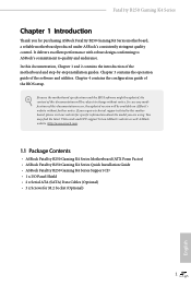
1.3 Motherboard Layout Fatal1ty B250 Gaming K4 Series 1 2 34 PS2 Keyboard /Mouse USB 2.0 T: USB1 B: USB2 ATX12V1 CT1 CPU_FAN1 M2_3 DDR4_A1 (64 bit, 288-pin module) DDR4_A2 (64 bit, 288-pin module) DDR4_B1 (...: FRONT Bottom: MIC IN 25 LAN PCIE1 CT4 PCI Express 3.0 CT3 CT2 CT1 PCIE2 CLRMOS1 1 M2_2 RoHS 24 1 FATAL TY CMOS Battery AUDIO CODEC PCIE3 B250 Gaming K4 Intel B250 PCIE4 Ultra M.2 PCIe Gen3 x4 T B2 T B1 23 1 1 SATA_0_1 SATA_2_3 SATA_4_5 1 7 8 9 M2_1 22 PCIE5 PCIE6 HD_AUDIO1 1 CI1 1 1 TPMS1 COM1 1 CT4 CT3 CT2 CT1 1 USB_7...
1.3 Motherboard Layout Fatal1ty B250 Gaming K4 Series 1 2 34 PS2 Keyboard /Mouse USB 2.0 T: USB1 B: USB2 ATX12V1 CT1 CPU_FAN1 M2_3 DDR4_A1 (64 bit, 288-pin module) DDR4_A2 (64 bit, 288-pin module) DDR4_B1 (...: FRONT Bottom: MIC IN 25 LAN PCIE1 CT4 PCI Express 3.0 CT3 CT2 CT1 PCIE2 CLRMOS1 1 M2_2 RoHS 24 1 FATAL TY CMOS Battery AUDIO CODEC PCIE3 B250 Gaming K4 Intel B250 PCIE4 Ultra M.2 PCIe Gen3 x4 T B2 T B1 23 1 1 SATA_0_1 SATA_2_3 SATA_4_5 1 7 8 9 M2_1 22 PCIE5 PCIE6 HD_AUDIO1 1 CI1 1 1 TPMS1 COM1 1 CT4 CT3 CT2 CT1 1 USB_7...

User Manual
Page 18
...touch the ICs. • Whenever you uninstall any motherboard settings. • Make sure to the chassis, please do so may damage the motherboard. 11 English Doing so may cause physical injuries and damages to motherboard components. • In order to avoid damage ... the motherboard's components, NEVER place your motherboard directly on a grounded anti-static pad or in the bag that the motherboard fits into it. Before you install motherboard components or change any components, place them on a carpet. Failure to do not overtighten the screws! Fatal1ty B250 Gaming K4 Series ...
...touch the ICs. • Whenever you uninstall any motherboard settings. • Make sure to the chassis, please do so may damage the motherboard. 11 English Doing so may cause physical injuries and damages to motherboard components. • In order to avoid damage ... the motherboard's components, NEVER place your motherboard directly on a grounded anti-static pad or in the bag that the motherboard fits into it. Before you install motherboard components or change any components, place them on a carpet. Failure to do not overtighten the screws! Fatal1ty B250 Gaming K4 Series ...

User Manual
Page 21
The cover must be placed if you wish to return the motherboard for after service. 14 English Please save and replace the cover if the processor is removed.
The cover must be placed if you wish to return the motherboard for after service. 14 English Please save and replace the cover if the processor is removed.

User Manual
Page 23
It is not allowed to install a DDR, DDR2 or DDR3 memory module into the slot at incorrect orientation. 2.3 Installing Memory Modules (DIMM) This motherboard provides four 288-pin DDR4 (Double Data Rate 4) DIMM slots, and supports Dual Channel Memory Technology. 1. It is unable to install identical (the ...same brand, speed, size and chip-type) DDR4 DIMM pairs. 2. It will cause permanent damage to the motherboard and the DIMM if you always need to activate Dual Channel Memory Technology with only one correct orientation. otherwise, this...
It is not allowed to install a DDR, DDR2 or DDR3 memory module into the slot at incorrect orientation. 2.3 Installing Memory Modules (DIMM) This motherboard provides four 288-pin DDR4 (Double Data Rate 4) DIMM slots, and supports Dual Channel Memory Technology. 1. It is unable to install identical (the ...same brand, speed, size and chip-type) DDR4 DIMM pairs. 2. It will cause permanent damage to the motherboard and the DIMM if you always need to activate Dual Channel Memory Technology with only one correct orientation. otherwise, this...

User Manual
Page 25
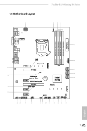
... Configurations Single Graphics Card PCIE2 x16 PCIE4 N/A Two Graphics Cards in CrossFireXTM Mode x16 x4 For a better thermal environment, please connect a chassis fan to the motherboard's chassis fan connector (CHA_FAN1 or CHA_FAN2) when using multiple graphics cards. Please read the documentation of the expansion card and make sure that the power... mode. * If M2_3 is used for PCI Express x16 lane width graphics cards. 2.4 Expansion Slots (PCI Express Slots) There are 6 PCI Express slots on the motherboard.
... Configurations Single Graphics Card PCIE2 x16 PCIE4 N/A Two Graphics Cards in CrossFireXTM Mode x16 x4 For a better thermal environment, please connect a chassis fan to the motherboard's chassis fan connector (CHA_FAN1 or CHA_FAN2) when using multiple graphics cards. Please read the documentation of the expansion card and make sure that the power... mode. * If M2_3 is used for PCI Express x16 lane width graphics cards. 2.4 Expansion Slots (PCI Express Slots) There are 6 PCI Express slots on the motherboard.

User Manual
Page 27
Do NOT place jumper caps over the headers and connectors will cause permanent damage to the motherboard. Note the positive and negative pins before connecting the cables. PWRBTN (Power Switch): Connect to the power status indicator on the chassis front panel. PLED (...
Do NOT place jumper caps over the headers and connectors will cause permanent damage to the motherboard. Note the positive and negative pins before connecting the cables. PWRBTN (Power Switch): Connect to the power status indicator on the chassis front panel. PLED (...

User Manual
Page 28
... be disabled. P+ USB_PWR USB_PWR PP+ GND DUMMY 1 GND P+ PUSB_PWR There are three USB 2.0 headers on this motherboard. SATA_5 SATA_3 These six SATA3 connectors support SATA data cables for internal storage devices with up to this motherboard. Fatal1ty B250 Gaming K4 Series Power LED and Speaker Header (7-pin SPK_PLED1) (see p.7, No. 11) Serial ATA3 Connectors (SATA_4_5: see...
... be disabled. P+ USB_PWR USB_PWR PP+ GND DUMMY 1 GND P+ PUSB_PWR There are three USB 2.0 headers on this motherboard. SATA_5 SATA_3 These six SATA3 connectors support SATA data cables for internal storage devices with up to this motherboard. Fatal1ty B250 Gaming K4 Series Power LED and Speaker Header (7-pin SPK_PLED1) (see p.7, No. 11) Serial ATA3 Connectors (SATA_4_5: see...

User Manual
Page 29
... chassis must support HDA to MIC2_L. C. Chassis Fan Connectors (4-pin CHA_FAN1) (see p.7, No. 13) (4-pin CHA_FAN2) (see p.7, No. 12) 4 3 21 FAN_SPEED_CONTROL CHA_FAN_SPEED FAN_VOLTAGE GND This motherboard provides two 4-Pin water cooling chassis fan connectors. B. D. E. Please follow the instructions in the Realtek Control panel and adjust "Recording Volume". To activate the front...
... chassis must support HDA to MIC2_L. C. Chassis Fan Connectors (4-pin CHA_FAN1) (see p.7, No. 13) (4-pin CHA_FAN2) (see p.7, No. 12) 4 3 21 FAN_SPEED_CONTROL CHA_FAN_SPEED FAN_VOLTAGE GND This motherboard provides two 4-Pin water cooling chassis fan connectors. B. D. E. Please follow the instructions in the Realtek Control panel and adjust "Recording Volume". To activate the front...

User Manual
Page 30
... Pin 1 and Pin 13. ATX 12V Power Connector (8-pin ATX12V1) (see p.7, No. 2) FAN_SPEED_CONTROL FAN_SPEED FAN_VOLTAGE GND 4 This motherboard pro- 3 2 vides a 4-Pin CPU fan 1 (Quiet Fan) connector. Fatal1ty B250 Gaming K4 Series CPU Fan Connector (4-pin CPU_FAN1) (see p.7, No. 1) 8 5 This motherboard pro- Thunderbolt AIC Connectors (5-pin TB1) (see p.7, No. 22) (10-pin TB2) (see p.7, No. 5) 12 24...
... Pin 1 and Pin 13. ATX 12V Power Connector (8-pin ATX12V1) (see p.7, No. 2) FAN_SPEED_CONTROL FAN_SPEED FAN_VOLTAGE GND 4 This motherboard pro- 3 2 vides a 4-Pin CPU fan 1 (Quiet Fan) connector. Fatal1ty B250 Gaming K4 Series CPU Fan Connector (4-pin CPU_FAN1) (see p.7, No. 1) 8 5 This motherboard pro- Thunderbolt AIC Connectors (5-pin TB1) (see p.7, No. 22) (10-pin TB2) (see p.7, No. 5) 12 24...

User Manual
Page 31
... Header (4-pin RGB_LED) (see p.7, No. 17) 1 12V G R B PCICLK FRAM E PCIRST # LAD3 +3V LAD0 +3VS B GN D GN D SMB_CLK_MAIN SMB_DATA_MAIN LAD2 LAD1 GN D S_PWRDWN # SERIRQ # GND This motherboard supports CASE OPEN detection feature that detects if the chassis cover has been removed.
... Header (4-pin RGB_LED) (see p.7, No. 17) 1 12V G R B PCICLK FRAM E PCIRST # LAD3 +3V LAD0 +3VS B GN D GN D SMB_CLK_MAIN SMB_DATA_MAIN LAD2 LAD1 GN D S_PWRDWN # SERIRQ # GND This motherboard supports CASE OPEN detection feature that detects if the chassis cover has been removed.
User Manual
Page 32
... two graphics cards by installing a CrossFire Bridge on the CrossFire Bridge Interconnects on the slots. Fatal1ty B250 Gaming K4 Series 2.7 CrossFireXTM and Quad CrossFireXTM Operation Guide This motherboard supports CrossFireXTM and Quad CrossFireXTM that allows you purchase, not bundled with this motherboard. Download the drivers from the AMD's website: www.amd.com 3. It is provided with...
... two graphics cards by installing a CrossFire Bridge on the CrossFire Bridge Interconnects on the slots. Fatal1ty B250 Gaming K4 Series 2.7 CrossFireXTM and Quad CrossFireXTM Operation Guide This motherboard supports CrossFireXTM and Quad CrossFireXTM that allows you purchase, not bundled with this motherboard. Download the drivers from the AMD's website: www.amd.com 3. It is provided with...

User Manual
Page 38
Skip Step 3 and 4 and go straight to Step 5 if you are going to secure the module into the M.2 slot. 4 3 2 1 D C B A D C B A D C B A C B A D NUT2 NUT1 Fatal1ty B250 Gaming K4 Series Step 3 Move the standoff based on the nut to be aware that the M.2 (NGFF) SSD module only fits in one orientation. Otherwise, release the ... English Please be used. The standoff is placed at the nut location D by hand. Hand tighten the standoff into the desired nut location on the motherboard.
Skip Step 3 and 4 and go straight to Step 5 if you are going to secure the module into the M.2 slot. 4 3 2 1 D C B A D C B A D C B A C B A D NUT2 NUT1 Fatal1ty B250 Gaming K4 Series Step 3 Move the standoff based on the nut to be aware that the M.2 (NGFF) SSD module only fits in one orientation. Otherwise, release the ... English Please be used. The standoff is placed at the nut location D by hand. Hand tighten the standoff into the desired nut location on the motherboard.
User Manual
Page 40
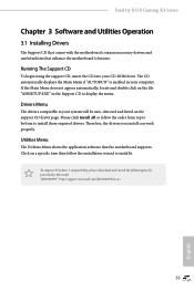
...Menu The Utilities Menu shows the application software that enhance the motherboard's features. Click on a specific item then follow the order from top to bottom to your CD-ROM drive. Fatal1ty B250 Gaming K4 Series Chapter 3 Software and Utilities Operation 3.1 Installing Drivers The ...Support CD that comes with the motherboard contains necessary drivers and useful utilities that the motherboard supports. Therefore, the drivers you install can ...
...Menu The Utilities Menu shows the application software that enhance the motherboard's features. Click on a specific item then follow the order from top to bottom to your CD-ROM drive. Fatal1ty B250 Gaming K4 Series Chapter 3 Software and Utilities Operation 3.1 Installing Drivers The ...Support CD that comes with the motherboard contains necessary drivers and useful utilities that the motherboard supports. Therefore, the drivers you install can ...

User Manual
Page 41
... selected the information panel below displays the relative information. 3.2 ASRock Live Update & APP Shop The ASRock Live Update & APP Shop is an online store for purchasing and downloading software applications for your motherboard up to date simply with a few clicks. Double-click utility. With ASRock APP Shop, you can quickly and easily install various...
... selected the information panel below displays the relative information. 3.2 ASRock Live Update & APP Shop The ASRock Live Update & APP Shop is an online store for purchasing and downloading software applications for your motherboard up to date simply with a few clicks. Double-click utility. With ASRock APP Shop, you can quickly and easily install various...
User Manual
Page 48
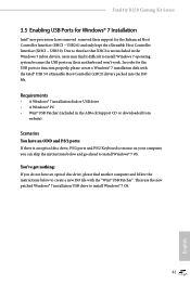
...Requirements • A Windows® 7 installation disk or USB drive • A Windows® PC • Win7 USB Patcher (included in the ASRock Support CD or downloaded from website) Scenarios You have an ODD and PS/2 ports: If there is not included in the Windows 7 inbox drivers,... file. Fatal1ty B250 Gaming K4 Series 3.5 Enabling USB Ports for Windows® 7 Installation Intel® new processors have an optical disc drive, please find it difficult to install Windows 7 operating system because the USB ports on your computer, you do not have removed removed their motherboard won't ...
...Requirements • A Windows® 7 installation disk or USB drive • A Windows® PC • Win7 USB Patcher (included in the ASRock Support CD or downloaded from website) Scenarios You have an ODD and PS/2 ports: If there is not included in the Windows 7 inbox drivers,... file. Fatal1ty B250 Gaming K4 Series 3.5 Enabling USB Ports for Windows® 7 Installation Intel® new processors have an optical disc drive, please find it difficult to install Windows 7 operating system because the USB ports on your computer, you do not have removed removed their motherboard won't ...

User Manual
Page 58
... will be lowered after a period of time until the CPU ratio is lowered when the Long Duration Power Limit is selected, the motherboard will expose the CPPC v2 interface to allow for hardware controlled P-states. GT Slice Current Limit Configure the current limit of the CPU... Core Current Limit Configure the current limit of the GT slice. When the limit is exceeded, the CPU ratio will be lowered immediately. Fatal1ty B250 Gaming K4 Series Intel Speed Shift Technology Enable/Disable Intel Speed Shift Technology support. A lower limit can protect the CPU and save power, while ...
... will be lowered after a period of time until the CPU ratio is lowered when the Long Duration Power Limit is selected, the motherboard will expose the CPPC v2 interface to allow for hardware controlled P-states. GT Slice Current Limit Configure the current limit of the CPU... Core Current Limit Configure the current limit of the GT slice. When the limit is exceeded, the CPU ratio will be lowered immediately. Fatal1ty B250 Gaming K4 Series Intel Speed Shift Technology Enable/Disable Intel Speed Shift Technology support. A lower limit can protect the CPU and save power, while ...

User Manual
Page 79
... a fan mode for CPU Fans 1, or choose Customize to monitor the status of the hardware on your system, including the parameters of the CPU temperature, motherboard temperature, fan speed and voltage.
... a fan mode for CPU Fans 1, or choose Customize to monitor the status of the hardware on your system, including the parameters of the CPU temperature, motherboard temperature, fan speed and voltage.


