
User Manual
Page 6
... CPU Fan and Heatsink 15 2.3 Installing Memory Modules (DIMM) 16 2.4 Expansion Slots (PCI Express Slots) 18 2.5 Jumpers Setup 19 2.6 Onboard Headers and Connectors 20 2.7 CrossFireXTM and Quad CrossFireXTM Operation Guide 25 2.7.1 Installing Two CrossFireXTM-Ready Graphics Cards 25 2.7.2 Driver Installation and Setup 27 2.8 M.2 WiFi/BT Module Installation Guide 28 2.9 M.2_SSD (NGFF) Module Installation Guide 30 Chapter 3 Software and Utilities Operation 33 3.1 Installing Drivers 33 3.2 ASRock Live Update & APP Shop 34 3.2.1 UI Overview 34 3.2.2 Apps 35 3.2.3 BIOS...
... CPU Fan and Heatsink 15 2.3 Installing Memory Modules (DIMM) 16 2.4 Expansion Slots (PCI Express Slots) 18 2.5 Jumpers Setup 19 2.6 Onboard Headers and Connectors 20 2.7 CrossFireXTM and Quad CrossFireXTM Operation Guide 25 2.7.1 Installing Two CrossFireXTM-Ready Graphics Cards 25 2.7.2 Driver Installation and Setup 27 2.8 M.2 WiFi/BT Module Installation Guide 28 2.9 M.2_SSD (NGFF) Module Installation Guide 30 Chapter 3 Software and Utilities Operation 33 3.1 Installing Drivers 33 3.2 ASRock Live Update & APP Shop 34 3.2.1 UI Overview 34 3.2.2 Apps 35 3.2.3 BIOS...
User Manual
Page 8
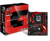
... BIOS setup. Because the motherboard specifications and the BIOS software might be updated, the content of this documentation will be subject to change without further notice. ASRock website http://www.asrock.com. 1.1 Package Contents • ASRock Fatal1ty B250 Gaming K4 Series Motherboard (ATX Form Factor) • ASRock Fatal1ty B250 Gaming K4 Series Quick Installation Guide • ASRock Fatal1ty B250 Gaming K4 Series Support CD • 1 x I/O Panel Shield • 2 x Serial ATA (SATA) Data Cables (Optional) • 3 x Screws for purchasing ASRock Fatal1ty B250 Gaming K4 Series...
... BIOS setup. Because the motherboard specifications and the BIOS software might be updated, the content of this documentation will be subject to change without further notice. ASRock website http://www.asrock.com. 1.1 Package Contents • ASRock Fatal1ty B250 Gaming K4 Series Motherboard (ATX Form Factor) • ASRock Fatal1ty B250 Gaming K4 Series Quick Installation Guide • ASRock Fatal1ty B250 Gaming K4 Series Support CD • 1 x I/O Panel Shield • 2 x Serial ATA (SATA) Data Cables (Optional) • 3 x Screws for purchasing ASRock Fatal1ty B250 Gaming K4 Series...
User Manual
Page 10
... Encode/Decode: VP8 , HEVC 8b; shared memory 1024MB * The size of maximum shared memory may vary from different operating systems. • Three graphics output options: D-Sub, DVI-D and HDMI • Supports Triple Monitor • Supports HDMI with max. Fatal1ty B250 Gaming K4 Series • Supports Intel® HD Graphics Built-in Visuals : Intel® Quick Sync Video with Differential Amplifier • TI® NE5532 Premium Headset Amplifier for R/L Audio Channel 3 English
... Encode/Decode: VP8 , HEVC 8b; shared memory 1024MB * The size of maximum shared memory may vary from different operating systems. • Three graphics output options: D-Sub, DVI-D and HDMI • Supports Triple Monitor • Supports HDMI with max. Fatal1ty B250 Gaming K4 Series • Supports Intel® HD Graphics Built-in Visuals : Intel® Quick Sync Video with Differential Amplifier • TI® NE5532 Premium Headset Amplifier for R/L Audio Channel 3 English
User Manual
Page 12
... M.2 PCI Express module up to Gen3 x2 (16 Gb/s)** ** Supports Intel® OptaneTM Technology (M2_1 only) ** Supports NVMe SSD as boot disks ** Supports ASRock U.2 Kit Connector • 1 x COM Port Header • 1 x TPM Header • 1 x Chassis Intrusion Header • 1 x Power LED and Speaker Header • 1 x CPU Fan Connector (4-pin) * The CPU Fan Connector supports the CPU fan of maximum 1A (12W) fan power. • 2 x Chassis Fan Connectors (4-pin) (Smart Fan Speed Control) • 1 x Chassis Optional/Water Pump Fan Connector (4-pin) * The Chassis Optional/Water Pump Fan supports...
... M.2 PCI Express module up to Gen3 x2 (16 Gb/s)** ** Supports Intel® OptaneTM Technology (M2_1 only) ** Supports NVMe SSD as boot disks ** Supports ASRock U.2 Kit Connector • 1 x COM Port Header • 1 x TPM Header • 1 x Chassis Intrusion Header • 1 x Power LED and Speaker Header • 1 x CPU Fan Connector (4-pin) * The CPU Fan Connector supports the CPU fan of maximum 1A (12W) fan power. • 2 x Chassis Fan Connectors (4-pin) (Smart Fan Speed Control) • 1 x Chassis Optional/Water Pump Fan Connector (4-pin) * The Chassis Optional/Water Pump Fan supports...
User Manual
Page 14
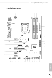
...-pin module) DDR4_B2 (64 bit, 288-pin module) ATXPWR1 5 HDMI1 USB 3.0 T: USB3_TA_1 Top: B: USB3_TC_1 RJ-45 USB 3.0 T: USB1 B: USB2 Top: Central/Bass LINE IN Center: REAR SPK Bottom: Optical SPDIF CHA_FAN2 6 USB3_3_4 Top: Center: FRONT Bottom: MIC IN 25 LAN PCIE1 CT4 PCI Express 3.0 CT3 CT2 CT1 PCIE2 CLRMOS1 1 M2_2 RoHS 24 1 FATAL TY CMOS Battery AUDIO CODEC PCIE3 B250 Gaming K4 Intel B250 PCIE4 Ultra M.2 PCIe...
...-pin module) DDR4_B2 (64 bit, 288-pin module) ATXPWR1 5 HDMI1 USB 3.0 T: USB3_TA_1 Top: B: USB3_TC_1 RJ-45 USB 3.0 T: USB1 B: USB2 Top: Central/Bass LINE IN Center: REAR SPK Bottom: Optical SPDIF CHA_FAN2 6 USB3_3_4 Top: Center: FRONT Bottom: MIC IN 25 LAN PCIE1 CT4 PCI Express 3.0 CT3 CT2 CT1 PCIE2 CLRMOS1 1 M2_2 RoHS 24 1 FATAL TY CMOS Battery AUDIO CODEC PCIE3 B250 Gaming K4 Intel B250 PCIE4 Ultra M.2 PCIe...

User Manual
Page 15
... (SATA_2_3) 9 SATA3 Connectors (SATA_0_1) 10 System Panel Header (PANEL1) 11 Power LED and Speaker Header (SPK_PLED1) 12 Chassis Fan / Waterpump Fan Connector (CHA_FAN3/W_PUMP) 13 Chassis Fan Connector (CHA_FAN1) 14 USB 2.0 Header (USB_3_4) 15 USB 2.0 Header (USB_5_6) 16 USB 2.0 Header (USB_7) 17 AURA RGB LED Header (RGB_LED) 18 COM Port Header (COM1) 19 TPM Header (TPMS1) 20 Chassis Intrusion Header (CI1) 21 Front Panel Audio Header (HD_AUDIO1) 22 Thunderbolt AIC Connector (TB1) 23 Thunderbolt AIC Connector (TB2) 24 Clear CMOS Jumper (CLRMOS1) 25 Chassis Fan Connector (CHA_FAN2) 8 English...
... (SATA_2_3) 9 SATA3 Connectors (SATA_0_1) 10 System Panel Header (PANEL1) 11 Power LED and Speaker Header (SPK_PLED1) 12 Chassis Fan / Waterpump Fan Connector (CHA_FAN3/W_PUMP) 13 Chassis Fan Connector (CHA_FAN1) 14 USB 2.0 Header (USB_3_4) 15 USB 2.0 Header (USB_5_6) 16 USB 2.0 Header (USB_7) 17 AURA RGB LED Header (RGB_LED) 18 COM Port Header (COM1) 19 TPM Header (TPMS1) 20 Chassis Intrusion Header (CI1) 21 Front Panel Audio Header (HD_AUDIO1) 22 Thunderbolt AIC Connector (TB1) 23 Thunderbolt AIC Connector (TB2) 24 Clear CMOS Jumper (CLRMOS1) 25 Chassis Fan Connector (CHA_FAN2) 8 English...

User Manual
Page 18
... you install the motherboard, study the configuration of your motherboard directly on a grounded anti-static pad or in the bag that the motherboard fits into it. Before you uninstall any motherboard settings. • Make sure to unplug the power cord before you handle the components. • Hold components by the edges and do not overtighten the screws! Fatal1ty B250 Gaming K4 Series Chapter 2 Installation...
... you install the motherboard, study the configuration of your motherboard directly on a grounded anti-static pad or in the bag that the motherboard fits into it. Before you uninstall any motherboard settings. • Make sure to unplug the power cord before you handle the components. • Hold components by the edges and do not overtighten the screws! Fatal1ty B250 Gaming K4 Series Chapter 2 Installation...

User Manual
Page 25
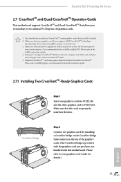
... 6 PCI Express slots on the motherboard. PCIE2 (PCIe 3.0 x16 slot) is used for PCI Express x4 lane width graphics cards. PCIE5 (PCIe 3.0 x1 slot) is used for the card before you start the installation. Before installing an expansion card, please make necessary hardware settings for PCI Express x1 lane width cards. PCIE3 (PCIe 3.0 x1 slot) is unplugged. PCIe Slot Configurations Single Graphics Card PCIE2 x16 PCIE4 N/A Two Graphics Cards in CrossFireXTM Mode x16 x4 For a better thermal environment, please connect a chassis fan to the motherboard's chassis fan connector...
... 6 PCI Express slots on the motherboard. PCIE2 (PCIe 3.0 x16 slot) is used for PCI Express x4 lane width graphics cards. PCIE5 (PCIe 3.0 x1 slot) is used for the card before you start the installation. Before installing an expansion card, please make necessary hardware settings for PCI Express x1 lane width cards. PCIE3 (PCIe 3.0 x1 slot) is unplugged. PCIe Slot Configurations Single Graphics Card PCIE2 x16 PCIE4 N/A Two Graphics Cards in CrossFireXTM Mode x16 x4 For a better thermal environment, please connect a chassis fan to the motherboard's chassis fan connector...

User Manual
Page 26
... 5 seconds. If you need to clear the CMOS when you just finish updating the BIOS, you must boot up the system first, and then shut it down before you to default setup, please turn off the computer and unplug the power cord from the power supply. English 19 Fatal1ty B250 Gaming K4 Series 2.5 Jumpers Setup The illustration shows how jumpers are "Short" when a jumper cap is placed on the pins, the jumper is "Short".
... 5 seconds. If you need to clear the CMOS when you just finish updating the BIOS, you must boot up the system first, and then shut it down before you to default setup, please turn off the computer and unplug the power cord from the power supply. English 19 Fatal1ty B250 Gaming K4 Series 2.5 Jumpers Setup The illustration shows how jumpers are "Short" when a jumper cap is placed on the pins, the jumper is "Short".

User Manual
Page 28
Fatal1ty B250 Gaming K4 Series Power LED and Speaker Header (7-pin SPK_PLED1) (see p.7, No. 11) Serial ATA3 Connectors (SATA_4_5: see p.7, No. 7) (SATA_2_3: see p.7, No. 8) (SATA_0_1: see p.7, No. 6) 1 GND P- P+ USB_PWR USB_PWR PP+ GND DUMMY 1 GND P+ PUSB_PWR There are three USB 2.0 headers on this motherboard. Vbus IntA_PA_SSRXIntA_PA_SSRX+ GND IntA_PA_SSTXIntA_PA_SSTX+ GND IntA_PA_DIntA_PA_D+ Vbus IntA_PB_SSRXIntA_PB_SSRX+ GND IntA_PB_SSTXIntA_PB_SSTX+ GND IntA_PB_DIntA_PB_D+ Dummy 1 Besides four USB 3.0 ports on the I/O panel, there is occupied by a SATA-type M.2 device, ...
Fatal1ty B250 Gaming K4 Series Power LED and Speaker Header (7-pin SPK_PLED1) (see p.7, No. 11) Serial ATA3 Connectors (SATA_4_5: see p.7, No. 7) (SATA_2_3: see p.7, No. 8) (SATA_0_1: see p.7, No. 6) 1 GND P- P+ USB_PWR USB_PWR PP+ GND DUMMY 1 GND P+ PUSB_PWR There are three USB 2.0 headers on this motherboard. Vbus IntA_PA_SSRXIntA_PA_SSRX+ GND IntA_PA_SSTXIntA_PA_SSTX+ GND IntA_PA_DIntA_PA_D+ Vbus IntA_PB_SSRXIntA_PB_SSRX+ GND IntA_PB_SSTXIntA_PB_SSTX+ GND IntA_PB_DIntA_PB_D+ Dummy 1 Besides four USB 3.0 ports on the I/O panel, there is occupied by a SATA-type M.2 device, ...

User Manual
Page 30
...Pin CPU fan, please connect it to PCIE4 (default slot). *Only one Thunderbolt AIC Card is supported on this motherboard. To use a 20-pin ATX power supply, please plug it along Pin 1 and Pin 13. ATX Power Connector (24-pin ATXPWR1) (see p.7, No. 1) 8 5 This motherboard pro- vides an 8-pin ATX 12V power connector. English 23 To use a 4 1 4-pin ATX power supply, please plug it along Pin 1 and Pin 5. ATX 12V Power Connector (8-pin ATX12V1) (see p.7, No. 5) 12 24 1 13 This motherboard provides a 24-pin ATX power connector. Thunderbolt AIC Connectors (5-pin...
...Pin CPU fan, please connect it to PCIE4 (default slot). *Only one Thunderbolt AIC Card is supported on this motherboard. To use a 20-pin ATX power supply, please plug it along Pin 1 and Pin 13. ATX Power Connector (24-pin ATXPWR1) (see p.7, No. 1) 8 5 This motherboard pro- vides an 8-pin ATX 12V power connector. English 23 To use a 4 1 4-pin ATX power supply, please plug it along Pin 1 and Pin 5. ATX 12V Power Connector (8-pin ATX12V1) (see p.7, No. 5) 12 24 1 13 This motherboard provides a 24-pin ATX power connector. Thunderbolt AIC Connectors (5-pin...
User Manual
Page 32
... refer to AMD graphics card manuals for detailed installation guide. 2.7.1 Installing Two CrossFireXTM-Ready Graphics Cards Step 1 Insert one graphics card into PCIE2 slot and the other graphics card to the AMD's website for details.) 25 English It is provided with the graphics card you purchase, not bundled with a 16-pipe card, both cards will operate as 12-pipe cards while in CrossFireXTM mode. 5. Fatal1ty B250 Gaming K4 Series 2.7 CrossFireXTM and Quad CrossFireXTM Operation Guide This motherboard supports CrossFireXTM...
... refer to AMD graphics card manuals for detailed installation guide. 2.7.1 Installing Two CrossFireXTM-Ready Graphics Cards Step 1 Insert one graphics card into PCIE2 slot and the other graphics card to the AMD's website for details.) 25 English It is provided with the graphics card you purchase, not bundled with a 16-pipe card, both cards will operate as 12-pipe cards while in CrossFireXTM mode. 5. Fatal1ty B250 Gaming K4 Series 2.7 CrossFireXTM and Quad CrossFireXTM Operation Guide This motherboard supports CrossFireXTM...
User Manual
Page 34
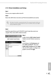
... to installation. We recommend using this utility to uninstall any VGA drivers installed in the Windows® system tray. Step 3 Install the required drivers and CATALYST Control Center then restart your computer and boot into OS. Step 5 In the left pane, click Performance and then AMD CrossFireXTM. Fatal1ty B250 Gaming K4 Series 2.7.2 Driver Installation and Setup Step 1 Power on your computer. English 27 Step 2 Remove the AMD drivers if you have any previously installed Catalyst drivers...
... to installation. We recommend using this utility to uninstall any VGA drivers installed in the Windows® system tray. Step 3 Install the required drivers and CATALYST Control Center then restart your computer and boot into OS. Step 5 In the left pane, click Performance and then AMD CrossFireXTM. Fatal1ty B250 Gaming K4 Series 2.7.2 Driver Installation and Setup Step 1 Power on your computer. English 27 Step 2 Remove the AMD drivers if you have any previously installed Catalyst drivers...
User Manual
Page 40
... the installation wizard to display the menu. If the Main Menu does not appear automatically, locate and double click on a specific item then follow the order from top to bottom to your system will be auto-detected and listed on the support CD driver page. Click on the file "ASRSETUP.EXE" in your CD-ROM drive. Utilities Menu The Utilities Menu shows the application software that enhance the motherboard's features...
... the installation wizard to display the menu. If the Main Menu does not appear automatically, locate and double click on a specific item then follow the order from top to bottom to your system will be auto-detected and listed on the support CD driver page. Click on the file "ASRSETUP.EXE" in your CD-ROM drive. Utilities Menu The Utilities Menu shows the application software that enhance the motherboard's features...
User Manual
Page 48
... install Windows® 7 OS. USB2.0) and only kept the eXtensible Host Controller Interface (XHCI - Fatal1ty B250 Gaming K4 Series 3.5 Enabling USB Ports for Windows® 7 Installation Intel® new processors have removed removed their motherboard won't work. Due to create a new ISO file with the Intel® USB 3.0 eXtensible Host Controller (xHCI) drivers packed into the ISO file. Requirements • A Windows® 7 installation disk or USB drive • A Windows® PC • Win7 USB Patcher (included in the ASRock Support CD or downloaded...
... install Windows® 7 OS. USB2.0) and only kept the eXtensible Host Controller Interface (XHCI - Fatal1ty B250 Gaming K4 Series 3.5 Enabling USB Ports for Windows® 7 Installation Intel® new processors have removed removed their motherboard won't work. Due to create a new ISO file with the Intel® USB 3.0 eXtensible Host Controller (xHCI) drivers packed into the ISO file. Requirements • A Windows® 7 installation disk or USB drive • A Windows® PC • Win7 USB Patcher (included in the ASRock Support CD or downloaded...

User Manual
Page 67
... external graphics card is used to route the interrupts it receives from peripheral buses to PIROI-PIROX. Share Memory Configure the size of the DMI Link. IGPU Multi-Monitor Select disable to the integrated graphics processor when the system boots up. Select enable to keep the integrated graphics enabled at all CPU downstream devices. PCIE4 Link Speed Select the link speed for enhanced PCI Express power saving in OS. PCIE ASPM Support This option enables/disables...
... external graphics card is used to route the interrupts it receives from peripheral buses to PIROI-PIROX. Share Memory Configure the size of the DMI Link. IGPU Multi-Monitor Select disable to the integrated graphics processor when the system boots up. Select enable to keep the integrated graphics enabled at all CPU downstream devices. PCIE4 Link Speed Select the link speed for enhanced PCI Express power saving in OS. PCIE ASPM Support This option enables/disables...

User Manual
Page 71
Serial Port Address Select the address of the Serial port. 4.6.5 Super IO Configuration Serial Port Enable or disable the Serial port. PS2 Y-Cable Enable the PS2 Y-Cable or set this option to Auto. 64 English
Serial Port Address Select the address of the Serial port. 4.6.5 Super IO Configuration Serial Port Enable or disable the Serial port. PS2 Y-Cable Enable the PS2 Y-Cable or set this option to Auto. 64 English
User Manual
Page 77
... setup network configuration before using Internet Flash. *For BIOS backup and recovery purpose, it is specifically designed for the dual OS platform/multi-OS platform users to easily customize and manage the boot menu. *Please connect more than one boot devices to plug in your USB storage device and run Instant Flash to wait for you. DHCP (Auto IP), Auto ASRock Internet Flash downloads and updates the latest UEFI firmware version from our servers for the Boot Manager. Boot Manager Enable/disable the Boot...
... setup network configuration before using Internet Flash. *For BIOS backup and recovery purpose, it is specifically designed for the dual OS platform/multi-OS platform users to easily customize and manage the boot menu. *Please connect more than one boot devices to plug in your USB storage device and run Instant Flash to wait for you. DHCP (Auto IP), Auto ASRock Internet Flash downloads and updates the latest UEFI firmware version from our servers for the Boot Manager. Boot Manager Enable/disable the Boot...

User Manual
Page 78
Internet Setting Enable or disable sound effects in the setup utility. Fatal1ty B250 Gaming K4 Series Network Configuration Use this to download the UEFI firmware. 71 English UEFI Download Server Select a server to configure internet connection settings for Internet Flash.
Internet Setting Enable or disable sound effects in the setup utility. Fatal1ty B250 Gaming K4 Series Network Configuration Use this to download the UEFI firmware. 71 English UEFI Download Server Select a server to configure internet connection settings for Internet Flash.

User Manual
Page 82
... settings in ME. Fatal1ty B250 Gaming K4 Series 4.9 Security Screen In this section you may also clear the user password. Secure Boot Use this option to remove the password. You may set or change the supervisor/user password for Windows 8.1 Secure Boot. Intel(R) Platform Trust Technology Enable/disable Intel PTT in the UEFI Setup Utility. Leave it blank and press enter to use discrete TPM Module. 75 English Disable this item to remove the password. Leave it blank and press enter to enable or disable support...
... settings in ME. Fatal1ty B250 Gaming K4 Series 4.9 Security Screen In this section you may also clear the user password. Secure Boot Use this option to remove the password. You may set or change the supervisor/user password for Windows 8.1 Secure Boot. Intel(R) Platform Trust Technology Enable/disable Intel PTT in the UEFI Setup Utility. Leave it blank and press enter to use discrete TPM Module. 75 English Disable this item to remove the password. Leave it blank and press enter to enable or disable support...


