User Manual
Page 2
... by the purchaser for a particular purpose. CALIFORNIA, USA ONLY The Lithium battery adopted on this documentation. "Perchlorate Material-special handling may appear in this motherboard contains Perchlorate, a toxic substance controlled in any form or by ASRock. Disclaimer: Specifications and information contained in this documentation may not cause harmful interference, and (2) this documentation...
... by the purchaser for a particular purpose. CALIFORNIA, USA ONLY The Lithium battery adopted on this documentation. "Perchlorate Material-special handling may appear in this motherboard contains Perchlorate, a toxic substance controlled in any form or by ASRock. Disclaimer: Specifications and information contained in this documentation may not cause harmful interference, and (2) this documentation...
User Manual
Page 4
... 24 2.7 Dual Graphics Operation Guide 28 2.8 Using the HDMI-In Port 30 3. Introduction 1 1.1 Package Contents 1 1.2 Specifications 2 1.3 Unique Features 6 1.4 WiFi-802.11n Module and ASRock WiFi 2.4/5GHz Antenna...... 11 1.5 Motherboard Layout 13 1.6 I/O Panel 15 2. Software and Utilities Operation 33 3.1 Installing Drivers 33 3.2 A-Tuning 34 3.3 Qualcomm® Atheros® Security Wake On Internet Technology...
... 24 2.7 Dual Graphics Operation Guide 28 2.8 Using the HDMI-In Port 30 3. Introduction 1 1.1 Package Contents 1 1.2 Specifications 2 1.3 Unique Features 6 1.4 WiFi-802.11n Module and ASRock WiFi 2.4/5GHz Antenna...... 11 1.5 Motherboard Layout 13 1.6 I/O Panel 15 2. Software and Utilities Operation 33 3.1 Installing Drivers 33 3.2 A-Tuning 34 3.3 Qualcomm® Atheros® Security Wake On Internet Technology...
User Manual
Page 6
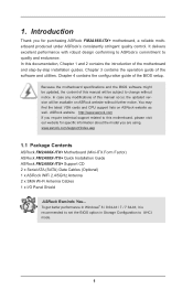
... latest VGA cards and CPU support lists on ASRock website without notice. 1. www.asrock.com/support/index.asp 1.1 Package Contents ASRock FM2A88X-ITX+ Motherboard (Mini-ITX Form Factor) ASRock FM2A88X-ITX+ Quick Installation Guide ASRock FM2A88X-ITX+ Support CD 2 x Serial ATA (SATA) Data Cables (Optional) 1 x ASRock WiFi 2.4/5GHz Antenna 2 x SMA Wi-Fi Antenna Cables 1 x I/O Panel Shield ASRock Reminds You... It delivers excellent performance with robust...
... latest VGA cards and CPU support lists on ASRock website without notice. 1. www.asrock.com/support/index.asp 1.1 Package Contents ASRock FM2A88X-ITX+ Motherboard (Mini-ITX Form Factor) ASRock FM2A88X-ITX+ Quick Installation Guide ASRock FM2A88X-ITX+ Support CD 2 x Serial ATA (SATA) Data Cables (Optional) 1 x ASRock WiFi 2.4/5GHz Antenna 2 x SMA Wi-Fi Antenna Cables 1 x I/O Panel Shield ASRock Reminds You... It delivers excellent performance with robust...
User Manual
Page 10
... 2400/2133/1866/1600MHz memory speed is supported depends on the CPU you want to adopt DDR3 2400/2133/1866/1600 memory module on this motherboard, please refer to the memory support list on our website for system usage under Windows® 8 / 7. HBR is supported under Windows® 8 64-...bit / 8 / 7 64-bit / 7. You can use . 3. WARNING Please realize that Windows® cannot use ASRock XFast RAM to utilize the memory that there is a certain risk involved with 64-bit CPU, there is no such limitation. CAUTION! 1. Deep Color mode...
... 2400/2133/1866/1600MHz memory speed is supported depends on the CPU you want to adopt DDR3 2400/2133/1866/1600 memory module on this motherboard, please refer to the memory support list on our website for system usage under Windows® 8 / 7. HBR is supported under Windows® 8 64-...bit / 8 / 7 64-bit / 7. You can use . 3. WARNING Please realize that Windows® cannot use ASRock XFast RAM to utilize the memory that there is a certain risk involved with 64-bit CPU, there is no such limitation. CAUTION! 1. Deep Color mode...
User Manual
Page 13
... change "SATA Mode" to "RAID", then you can start installing the OS in RAID mode. 8 You may prevent motherboard damages due to dehumidify the system after entering S4/S5 state. ASRock UEFI System Browser ASRock UEFI system browser is a useful tool included in graphical UEFI. It can detect the devices and configurations that...
... change "SATA Mode" to "RAID", then you can start installing the OS in RAID mode. 8 You may prevent motherboard damages due to dehumidify the system after entering S4/S5 state. ASRock UEFI System Browser ASRock UEFI system browser is a useful tool included in graphical UEFI. It can detect the devices and configurations that...
User Manual
Page 16
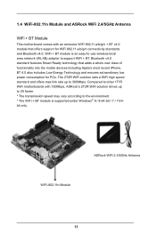
...The WiFi + BT module is an easy-to-use wireless local area network (WLAN) adapter to support WiFi + BT. Compared to other 1T1R WiFi motherboards with an exclusive WiFi 802.11 a/b/g/n + BT v4.0 module that adds a whole new class of functionality into the mobile devices including Apple's most recent... connectivity standards and Bluetooth v4.0. Bluetooth v4.0 standard features Smart Ready technology that offers support for PCs. 1.4 WiFi-802.11n Module and ASRock WiFi 2.4/5GHz Antenna WiFi + BT Module This motherboard comes with 150Mbps, ASRock's 2T2R WiFi solution drives up to 300Mbps.
...The WiFi + BT module is an easy-to-use wireless local area network (WLAN) adapter to support WiFi + BT. Compared to other 1T1R WiFi motherboards with an exclusive WiFi 802.11 a/b/g/n + BT v4.0 module that adds a whole new class of functionality into the mobile devices including Apple's most recent... connectivity standards and Bluetooth v4.0. Bluetooth v4.0 standard features Smart Ready technology that offers support for PCs. 1.4 WiFi-802.11n Module and ASRock WiFi 2.4/5GHz Antenna WiFi + BT Module This motherboard comes with 150Mbps, ASRock's 2T2R WiFi solution drives up to 300Mbps.
User Manual
Page 17
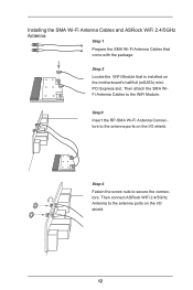
Step 4 Fasten the screw nuts to the antenna ports on the I /O shield. Then connect ASRock WiFi 2.4/5GHz Antenna to secure the connectors. Installing the SMA Wi-Fi Antenna Cables and ASRock WiFi 2.4/5GHz Antenna Step 1 Prepare the SMA Wi-Fi Antenna Cables that is installed on the I /O shield. 12 Then attach the SMA WiFi Antenna Cables to the antenna ports on the motherboard's half/full (mSATA) miniPCI Express slot. Step3 Insert the RP-SMA Wi-Fi Antenna Connectors to the WiFi Module. Step 2 Locate the WiFi Module that come with the package.
Step 4 Fasten the screw nuts to the antenna ports on the I /O shield. Then connect ASRock WiFi 2.4/5GHz Antenna to secure the connectors. Installing the SMA Wi-Fi Antenna Cables and ASRock WiFi 2.4/5GHz Antenna Step 1 Prepare the SMA Wi-Fi Antenna Cables that is installed on the I /O shield. 12 Then attach the SMA WiFi Antenna Cables to the antenna ports on the motherboard's half/full (mSATA) miniPCI Express slot. Step3 Insert the RP-SMA Wi-Fi Antenna Connectors to the WiFi Module. Step 2 Locate the WiFi Module that come with the package.
User Manual
Page 18
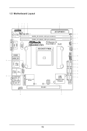
HDLED RESET 1.5 Motherboard Layout DVI1 VGA1 TPMS1 1 PS2 USB 2.0 Keyboard T: USB0 /Mouse B: USB1 1 1 CPU_FAN1 CI1 CMOS Battery CLRCMOS1 AT X P W R 1 DDR3_B1 (64 bit, 240-pin module) DDR3_A1 (64 bit, 240-pin module) PCI Express 3.0 FM2A88X-ITX+ Front USB 3.0 RoHS SOCKET FM2b CHA_FAN1 PLED PWRBTN SPEAKER1 1 PANEL1 1 HDMI1 HDMI_IN1 eSATA3_1 USB_67 USB 2.0 T: USB2 B: USB3 1 USB 3.0 T: USB2...
HDLED RESET 1.5 Motherboard Layout DVI1 VGA1 TPMS1 1 PS2 USB 2.0 Keyboard T: USB0 /Mouse B: USB1 1 1 CPU_FAN1 CI1 CMOS Battery CLRCMOS1 AT X P W R 1 DDR3_B1 (64 bit, 240-pin module) DDR3_A1 (64 bit, 240-pin module) PCI Express 3.0 FM2A88X-ITX+ Front USB 3.0 RoHS SOCKET FM2b CHA_FAN1 PLED PWRBTN SPEAKER1 1 PANEL1 1 HDMI1 HDMI_IN1 eSATA3_1 USB_67 USB 2.0 T: USB2 B: USB3 1 USB 3.0 T: USB2...
User Manual
Page 22
... or change any component, ensure that the power is switched off or the power cord is a Mini-ITX form factor motherboard. To avoid damaging the motherboard components due to static electricity, NEVER place your chassis to the chassis, please do not touch the ICs. 4. When placing screws into it on the ...
... or change any component, ensure that the power is switched off or the power cord is a Mini-ITX form factor motherboard. To avoid damaging the motherboard components due to static electricity, NEVER place your chassis to the chassis, please do not touch the ICs. 4. When placing screws into it on the ...
User Manual
Page 24
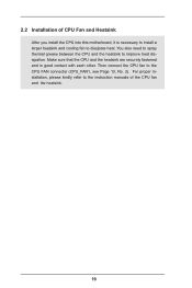
You also need to spray thermal grease between the CPU and the heatsink to the CPU FAN connector (CPU_FAN1, see Page 13, No. 2). Make sure that the CPU and the heatsink are securely fastened and in good contact with each other. Then connect the CPU fan to improve heat dissipation. For proper installation, please kindly refer to dissipate heat. 2.2 Installation of CPU Fan and Heatsink After you install the CPU into this motherboard, it is necessary to install a larger heatsink and cooling fan to the instruction manuals of the CPU fan and the heatsink. 19
You also need to spray thermal grease between the CPU and the heatsink to the CPU FAN connector (CPU_FAN1, see Page 13, No. 2). Make sure that the CPU and the heatsink are securely fastened and in good contact with each other. Then connect the CPU fan to improve heat dissipation. For proper installation, please kindly refer to dissipate heat. 2.2 Installation of CPU Fan and Heatsink After you install the CPU into this motherboard, it is necessary to install a larger heatsink and cooling fan to the instruction manuals of the CPU fan and the heatsink. 19
User Manual
Page 25
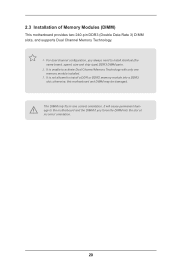
It will cause permanent damage to activate Dual Channel Memory Technology with only one correct orientation. It is unable to the motherboard and the DIMM if you always need to install a DDR or DDR2 memory module into the slot at incorrect orientation. 20 For dual channel configuration,.... 3. It is not allowed to install identical (the same brand, speed, size and chip-type) DDR3 DIMM pairs. 2. 2.3 Installation of Memory Modules (DIMM) This motherboard provides two 240-pin DDR3 (Double Data Rate 3) DIMM slots, and supports Dual Channel Memory Technology. 1. otherwise, this...
It will cause permanent damage to activate Dual Channel Memory Technology with only one correct orientation. It is unable to the motherboard and the DIMM if you always need to install a DDR or DDR2 memory module into the slot at incorrect orientation. 20 For dual channel configuration,.... 3. It is not allowed to install identical (the same brand, speed, size and chip-type) DDR3 DIMM pairs. 2. 2.3 Installation of Memory Modules (DIMM) This motherboard provides two 240-pin DDR3 (Double Data Rate 3) DIMM slots, and supports Dual Channel Memory Technology. 1. otherwise, this...
User Manual
Page 27
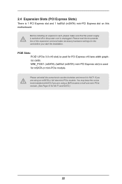
... that the power supply is switched off or the power cord is 1 PCI Express slot and 1 half/full (mSATA) mini-PCI Express slot on this motherboard. MINI_PCIE1 (mSATA) (half/full (mSATA) mini-PCI Express slot) is used for the card before you start the installation. Please uninstall the screw knob counterclockwise...
... that the power supply is switched off or the power cord is 1 PCI Express slot and 1 half/full (mSATA) mini-PCI Express slot on this motherboard. MINI_PCIE1 (mSATA) (half/full (mSATA) mini-PCI Express slot) is used for the card before you start the installation. Please uninstall the screw knob counterclockwise...
User Manual
Page 29
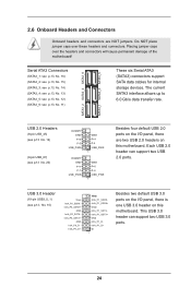
Do NOT place jumper caps over the headers and connectors will cause permanent damage of the motherboard! The current SATA3 interface allows up to 6.0 Gb/s data transfer rate. USB 3.0 Header (19-pin USB3_0_1) (see p.13, No. 10) Vbus ... USB_PWR DUMMY GND P+7 P-7 USB_PWR GND P+4 P-4 USB_PWR 1 GND P+6 P-6 USB_PWR 1 Besides four default USB 2.0 ports on the I /O panel, there is one USB 3.0 header on this motherboard. Each USB 2.0 header can support two USB 3.0 ports. 24 SATA3_2 SATA3_4 SATA3_6 SATA3_1 SATA3_3 SATA3_5 USB 2.0 Headers (9-pin USB_45) (see p.13 No. 19) (9-pin USB_67...
Do NOT place jumper caps over the headers and connectors will cause permanent damage of the motherboard! The current SATA3 interface allows up to 6.0 Gb/s data transfer rate. USB 3.0 Header (19-pin USB3_0_1) (see p.13, No. 10) Vbus ... USB_PWR DUMMY GND P+7 P-7 USB_PWR GND P+4 P-4 USB_PWR 1 GND P+6 P-6 USB_PWR 1 Besides four default USB 2.0 ports on the I /O panel, there is one USB 3.0 header on this motherboard. Each USB 2.0 header can support two USB 3.0 ports. 24 SATA3_2 SATA3_4 SATA3_6 SATA3_1 SATA3_3 SATA3_5 USB 2.0 Headers (9-pin USB_45) (see p.13 No. 19) (9-pin USB_67...
User Manual
Page 31
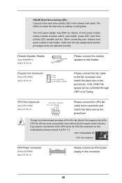
... the connector and match the black wire to this header, make sure the wire assignments and the pin assign-ments are matched correctly. Though this motherboard, please connect it to Pin 1-3. CPU Fan Connector FAN_SPEED_CONTROL (4-pin CPU_FAN1) CPU_FAN_SPEED +12V (see p.13 No. 6) Please connect the chassis speaker to the ...writing data. If you plan to connect the 3-Pin CPU fan to the CPU fan connector on when the hard drive is on this motherboard provides 4-Pin CPU fan (Quiet Fan) support, the 3-Pin CPU fan still can be controlled through UEFI or A-Tuning.
... the connector and match the black wire to this header, make sure the wire assignments and the pin assign-ments are matched correctly. Though this motherboard, please connect it to Pin 1-3. CPU Fan Connector FAN_SPEED_CONTROL (4-pin CPU_FAN1) CPU_FAN_SPEED +12V (see p.13 No. 6) Please connect the chassis speaker to the ...writing data. If you plan to connect the 3-Pin CPU fan to the CPU fan connector on when the hard drive is on this motherboard provides 4-Pin CPU fan (Quiet Fan) support, the 3-Pin CPU fan still can be controlled through UEFI or A-Tuning.
User Manual
Page 32
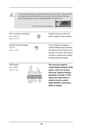
TPM Header (17-pin TPMS1) (see p.13, No. 3) 1 GND Signal Please connect an ATX 12V power supply to this motherboard provides 24-pin ATX power connector, it can securely store keys, digital certificates, passwords, and data. This feature requires a chassis with ... To use the 20-pin ATX power supply, please plug your power supply along with chassis intrusion detection design. Though this connector. This motherboard supports CASE OPEN detection feature that detects if the chassis cover has been removed. A TPM system also helps enhance network security, protects digital...
TPM Header (17-pin TPMS1) (see p.13, No. 3) 1 GND Signal Please connect an ATX 12V power supply to this motherboard provides 24-pin ATX power connector, it can securely store keys, digital certificates, passwords, and data. This feature requires a chassis with ... To use the 20-pin ATX power supply, please plug your power supply along with chassis intrusion detection design. Though this connector. This motherboard supports CASE OPEN detection feature that detects if the chassis cover has been removed. A TPM system also helps enhance network security, protects digital...
User Manual
Page 33
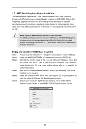
... the onboard VGA and the discrete graphics card. An AMD Dual Graphics system includes an AMD Radeon HD 8000/7000 graphics processor and a motherboard based on [Auto]. Connect the monitor cable to enter AMD VISION Engine Control Center. 28 Step 5. Install the onboard VGA driver from ..." option on an AMD A88X (Bolton-D4) integrated chipset, all operating in your system. Step 6. 2.7 AMD Dual Graphics Operation Guide This motherboard supports AMD Dual Graphics feature. Install one AMD RADEON PCI Express graphics card to your computer. Please remove the AMD driver if you have any...
... the onboard VGA and the discrete graphics card. An AMD Dual Graphics system includes an AMD Radeon HD 8000/7000 graphics processor and a motherboard based on [Auto]. Connect the monitor cable to enter AMD VISION Engine Control Center. 28 Step 5. Install the onboard VGA driver from ..." option on an AMD A88X (Bolton-D4) integrated chipset, all operating in your system. Step 6. 2.7 AMD Dual Graphics Operation Guide This motherboard supports AMD Dual Graphics feature. Install one AMD RADEON PCI Express graphics card to your computer. Please remove the AMD driver if you have any...
User Manual
Page 35
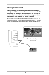
... mode or powered off. This function saves you the hassle of switching cables back and forth when you want to display the screen of this motherboard lets you can be viewed even when your PC screen.
... mode or powered off. This function saves you the hassle of switching cables back and forth when you want to display the screen of this motherboard lets you can be viewed even when your PC screen.
User Manual
Page 37
... (on the desktop and find "HDMI-IN" function in BIOS SETUP is no video displayed on your monitor to the HDMI-Out port on the motherboard via an HDMI cable. If required, connect a power source to "Hotkey:" and enter the action for the key. 1. or Use the hotkey to switch between... on the motherboard via an HDMI cable. Step 2 Connect an external devices with HDMI output to the HDMI-In port on -board PC screen or HDMI-In Source...
... (on the desktop and find "HDMI-IN" function in BIOS SETUP is no video displayed on your monitor to the HDMI-Out port on the motherboard via an HDMI cable. If required, connect a power source to "Hotkey:" and enter the action for the key. 1. or Use the hotkey to switch between... on the motherboard via an HDMI cable. Step 2 Connect an external devices with HDMI output to the HDMI-In port on -board PC screen or HDMI-In Source...
User Manual
Page 38
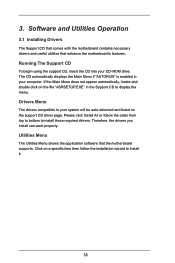
... the menu. Click on the support CD driver page. 3. Utilities Menu The Utilities Menu shows the application software that enhance the motherboard's features. The CD automatically displays the Main Menu if "AUTORUN" is enabled in the Support CD to install those required drivers....install can work properly. Software and Utilities Operation 3.1 Installing Drivers The Support CD that comes with the motherboard contains necessary drivers and useful utilities that the motherboard supports. Please click Install All or follow the installation wizard to install it. 33 If the Main ...
... the menu. Click on the support CD driver page. 3. Utilities Menu The Utilities Menu shows the application software that enhance the motherboard's features. The CD automatically displays the Main Menu if "AUTORUN" is enabled in the Support CD to install those required drivers....install can work properly. Software and Utilities Operation 3.1 Installing Drivers The Support CD that comes with the motherboard contains necessary drivers and useful utilities that the motherboard supports. Please click Install All or follow the installation wizard to install it. 33 If the Main ...
User Manual
Page 41
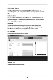
... on, and the duration of the dehumidifying process. Please set a hotkey for overclocking the system. System Info View information about the system. 36 Dehumidifier Prevent motherboard damages due to the next speed level when the assigned temperature is met. FAN-Tastic Tuning Configure up to one monitor and toggle between the...
... on, and the duration of the dehumidifying process. Please set a hotkey for overclocking the system. System Info View information about the system. 36 Dehumidifier Prevent motherboard damages due to the next speed level when the assigned temperature is met. FAN-Tastic Tuning Configure up to one monitor and toggle between the...


