User Manual
Page 2
..., employees, or agents be constructed as a commitment by the California Legislature. Products and corporate names appearing in this motherboard contains Perchlorate, a toxic substance controlled in advance. Version 1.1 Published September 2013 Copyright©2013 ASRock INC. When you discard the Lithium battery in California, USA, please follow the related regulations in Perchlorate Best...
..., employees, or agents be constructed as a commitment by the California Legislature. Products and corporate names appearing in this motherboard contains Perchlorate, a toxic substance controlled in advance. Version 1.1 Published September 2013 Copyright©2013 ASRock INC. When you discard the Lithium battery in California, USA, please follow the related regulations in Perchlorate Best...
User Manual
Page 4
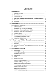
... 34 3.3 Qualcomm® Atheros® Security Wake On Internet Technology... 38 3.4 Start8 45 4. Contents 1. Introduction 1 1.1 Package Contents 1 1.2 Specifications 2 1.3 Unique Features 6 1.4 WiFi-802.11n Module and ASRock WiFi 2.4/5GHz Antenna...... 11 1.5 Motherboard Layout 13 1.6 I/O Panel 15 2.
... 34 3.3 Qualcomm® Atheros® Security Wake On Internet Technology... 38 3.4 Start8 45 4. Contents 1. Introduction 1 1.1 Package Contents 1 1.2 Specifications 2 1.3 Unique Features 6 1.4 WiFi-802.11n Module and ASRock WiFi 2.4/5GHz Antenna...... 11 1.5 Motherboard Layout 13 1.6 I/O Panel 15 2.
User Manual
Page 6
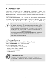
... BIOS option in Storage Configuration to quality and endurance. www.asrock.com/support/index.asp 1.1 Package Contents ASRock FM2A88X-ITX+ Motherboard (Mini-ITX Form Factor) ASRock FM2A88X-ITX+ Quick Installation Guide ASRock FM2A88X-ITX+ Support CD 2 x Serial ATA (SATA) Data Cables (Optional) 1 x ASRock WiFi 2.4/5GHz Antenna 2 x SMA Wi-Fi Antenna Cables 1 x I/O Panel Shield ASRock Reminds You... It delivers excellent performance with robust design conforming...
... BIOS option in Storage Configuration to quality and endurance. www.asrock.com/support/index.asp 1.1 Package Contents ASRock FM2A88X-ITX+ Motherboard (Mini-ITX Form Factor) ASRock FM2A88X-ITX+ Quick Installation Guide ASRock FM2A88X-ITX+ Support CD 2 x Serial ATA (SATA) Data Cables (Optional) 1 x ASRock WiFi 2.4/5GHz Antenna 2 x SMA Wi-Fi Antenna Cables 1 x I/O Panel Shield ASRock Reminds You... It delivers excellent performance with robust design conforming...
User Manual
Page 10
... limitation. Due to the memory support list on the CPU you want to adopt DDR3 2400/2133/1866/1600 memory module on this motherboard, please refer to the operating system limitation, the actual memory size may affect your system. Deep Color mode will be done at ...not responsible for possible damage caused by overclocking. For Windows® 64-bit OS with overclocking, including adjusting the setting in EDID. ASRock website http://www.asrock.com 2. CAUTION! 1. Overclocking may be less than 4GB for the reservation for the compatible memory modules. We are only supported ...
... limitation. Due to the memory support list on the CPU you want to adopt DDR3 2400/2133/1866/1600 memory module on this motherboard, please refer to the operating system limitation, the actual memory size may affect your system. Deep Color mode will be done at ...not responsible for possible damage caused by overclocking. For Windows® 64-bit OS with overclocking, including adjusting the setting in EDID. ASRock website http://www.asrock.com 2. CAUTION! 1. Overclocking may be less than 4GB for the reservation for the compatible memory modules. We are only supported ...
User Manual
Page 13
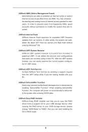
... When enabling Dehumidifier Function, the computer will power on automatically to prevent users from our servers. ASRock OMG (Online Management Guard) Administrators are required. You may prevent motherboard damages due to "RAID", then you can autodetect the latest UEFI from the UEFI setup utility if... you are currently using in graphical UEFI. ASRock Easy RAID Installer ASRock Easy RAID Installer can help you can detect ...
... When enabling Dehumidifier Function, the computer will power on automatically to prevent users from our servers. ASRock OMG (Online Management Guard) Administrators are required. You may prevent motherboard damages due to "RAID", then you can autodetect the latest UEFI from the UEFI setup utility if... you are currently using in graphical UEFI. ASRock Easy RAID Installer ASRock Easy RAID Installer can help you can detect ...
User Manual
Page 16
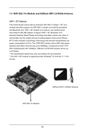
... and ensures extraordinary low power consumption for WiFi 802.11 a/b/g/n connectivity standards and Bluetooth v4.0. Compared to other 1T1R WiFi motherboards with an exclusive WiFi 802.11 a/b/g/n + BT v4.0 module that adds a whole new class of functionality into the mobile... only. Bluetooth v4.0 standard features Smart Ready technology that offers support for PCs. ASRock WiFi 2.4/5GHz Antenna WiFi-802.11n Module 11 1.4 WiFi-802.11n Module and ASRock WiFi 2.4/5GHz Antenna WiFi + BT Module This motherboard comes with 150Mbps, ASRock's 2T2R WiFi solution drives up to support WiFi + BT.
... and ensures extraordinary low power consumption for WiFi 802.11 a/b/g/n connectivity standards and Bluetooth v4.0. Compared to other 1T1R WiFi motherboards with an exclusive WiFi 802.11 a/b/g/n + BT v4.0 module that adds a whole new class of functionality into the mobile... only. Bluetooth v4.0 standard features Smart Ready technology that offers support for PCs. ASRock WiFi 2.4/5GHz Antenna WiFi-802.11n Module 11 1.4 WiFi-802.11n Module and ASRock WiFi 2.4/5GHz Antenna WiFi + BT Module This motherboard comes with 150Mbps, ASRock's 2T2R WiFi solution drives up to support WiFi + BT.
User Manual
Page 17
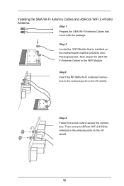
Step 4 Fasten the screw nuts to the WiFi Module. Step3 Insert the RP-SMA Wi-Fi Antenna Connectors to the antenna ports on the I /O shield. Step 2 Locate the WiFi Module that come with the package. Then attach the SMA WiFi Antenna Cables to secure the connectors. Then connect ASRock WiFi 2.4/5GHz Antenna to the antenna ports on the I /O shield. 12 Installing the SMA Wi-Fi Antenna Cables and ASRock WiFi 2.4/5GHz Antenna Step 1 Prepare the SMA Wi-Fi Antenna Cables that is installed on the motherboard's half/full (mSATA) miniPCI Express slot.
Step 4 Fasten the screw nuts to the WiFi Module. Step3 Insert the RP-SMA Wi-Fi Antenna Connectors to the antenna ports on the I /O shield. Step 2 Locate the WiFi Module that come with the package. Then attach the SMA WiFi Antenna Cables to secure the connectors. Then connect ASRock WiFi 2.4/5GHz Antenna to the antenna ports on the I /O shield. 12 Installing the SMA Wi-Fi Antenna Cables and ASRock WiFi 2.4/5GHz Antenna Step 1 Prepare the SMA Wi-Fi Antenna Cables that is installed on the motherboard's half/full (mSATA) miniPCI Express slot.
User Manual
Page 18
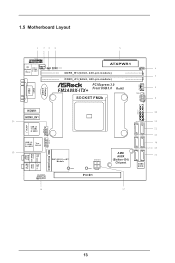
HDLED RESET 1.5 Motherboard Layout DVI1 VGA1 TPMS1 1 PS2 USB 2.0 Keyboard T: USB0 /Mouse B: USB1 1 1 CPU_FAN1 CI1 CMOS Battery CLRCMOS1 AT X P W R 1 DDR3_B1 (64 bit, 240-pin module) DDR3_A1 (64 bit, 240-pin module) PCI Express 3.0 FM2A88X-ITX+ Front USB 3.0 RoHS SOCKET FM2b CHA_FAN1 PLED PWRBTN SPEAKER1 1 PANEL1 1 HDMI1 HDMI_IN1 eSATA3_1 USB_67 USB 2.0 T: USB2 B: USB3 1 USB 3.0 T: USB2...
HDLED RESET 1.5 Motherboard Layout DVI1 VGA1 TPMS1 1 PS2 USB 2.0 Keyboard T: USB0 /Mouse B: USB1 1 1 CPU_FAN1 CI1 CMOS Battery CLRCMOS1 AT X P W R 1 DDR3_B1 (64 bit, 240-pin module) DDR3_A1 (64 bit, 240-pin module) PCI Express 3.0 FM2A88X-ITX+ Front USB 3.0 RoHS SOCKET FM2b CHA_FAN1 PLED PWRBTN SPEAKER1 1 PANEL1 1 HDMI1 HDMI_IN1 eSATA3_1 USB_67 USB 2.0 T: USB2 B: USB3 1 USB 3.0 T: USB2...
User Manual
Page 22
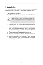
...motherboard fits into the screw holes to secure the motherboard to do so may damage the motherboard.... 17 Whenever you handle components. 3. Before you install or remove any component, place it . 2. Before you install the motherboard, study the configuration of the following precautions before touching any motherboard... settings. Installation This is detached from the wall socket before you install motherboard...your motherboard ...
...motherboard fits into the screw holes to secure the motherboard to do so may damage the motherboard.... 17 Whenever you handle components. 3. Before you install or remove any component, place it . 2. Before you install the motherboard, study the configuration of the following precautions before touching any motherboard... settings. Installation This is detached from the wall socket before you install motherboard...your motherboard ...
User Manual
Page 24
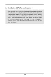
Make sure that the CPU and the heatsink are securely fastened and in good contact with each other. 2.2 Installation of CPU Fan and Heatsink After you install the CPU into this motherboard, it is necessary to install a larger heatsink and cooling fan to the instruction manuals of the CPU fan and the heatsink. 19 For proper installation, please kindly refer to dissipate heat. Then connect the CPU fan to improve heat dissipation. You also need to spray thermal grease between the CPU and the heatsink to the CPU FAN connector (CPU_FAN1, see Page 13, No. 2).
Make sure that the CPU and the heatsink are securely fastened and in good contact with each other. 2.2 Installation of CPU Fan and Heatsink After you install the CPU into this motherboard, it is necessary to install a larger heatsink and cooling fan to the instruction manuals of the CPU fan and the heatsink. 19 For proper installation, please kindly refer to dissipate heat. Then connect the CPU fan to improve heat dissipation. You also need to spray thermal grease between the CPU and the heatsink to the CPU FAN connector (CPU_FAN1, see Page 13, No. 2).
User Manual
Page 25
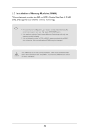
...not allowed to install identical (the same brand, speed, size and chip-type) DDR3 DIMM pairs. 2. otherwise, this motherboard and DIMM may be damaged. It is unable to the motherboard and the DIMM if you always need to install a DDR or DDR2 memory module into the slot at incorrect orientation. 20...DDR3 slot; It will cause permanent damage to activate Dual Channel Memory Technology with only one correct orientation. 2.3 Installation of Memory Modules (DIMM) This motherboard provides two 240-pin DDR3 (Double Data Rate 3) DIMM slots, and supports Dual Channel Memory Technology. 1.
...not allowed to install identical (the same brand, speed, size and chip-type) DDR3 DIMM pairs. 2. otherwise, this motherboard and DIMM may be damaged. It is unable to the motherboard and the DIMM if you always need to install a DDR or DDR2 memory module into the slot at incorrect orientation. 20...DDR3 slot; It will cause permanent damage to activate Dual Channel Memory Technology with only one correct orientation. 2.3 Installation of Memory Modules (DIMM) This motherboard provides two 240-pin DDR3 (Double Data Rate 3) DIMM slots, and supports Dual Channel Memory Technology. 1.
User Manual
Page 27
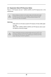
... for NUT1 and NUT2.) 22 PCIE Slots: PCIE1 (PCIe 3.0 x16 slot) is 1 PCI Express slot and 1 half/full (mSATA) mini-PCI Express slot on this motherboard. Please read the documentation of the expansion card and make sure that the power supply is switched off or the power cord is used for...
... for NUT1 and NUT2.) 22 PCIE Slots: PCIE1 (PCIe 3.0 x16 slot) is 1 PCI Express slot and 1 half/full (mSATA) mini-PCI Express slot on this motherboard. Please read the documentation of the expansion card and make sure that the power supply is switched off or the power cord is used for...
User Manual
Page 29
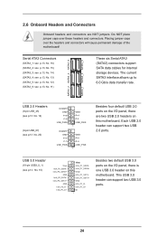
... DUMMY GND P+7 P-7 USB_PWR GND P+4 P-4 USB_PWR 1 GND P+6 P-6 USB_PWR 1 Besides four default USB 2.0 ports on the I /O panel, there is one USB 3.0 header on this motherboard. The current SATA3 interface allows up to 6.0 Gb/s data transfer rate. Serial ATA3 Connectors (SATA3_1: see p.13, No. 16) (SATA3_2: see p.13, No. 15) (SATA3_3... 3.0 header can support two USB 2.0 ports. 2.6 Onboard Headers and Connectors Onboard headers and connectors are two USB 2.0 headers on this motherboard. Do NOT place jumper caps over the headers and connectors will cause permanent damage of the...
... DUMMY GND P+7 P-7 USB_PWR GND P+4 P-4 USB_PWR 1 GND P+6 P-6 USB_PWR 1 Besides four default USB 2.0 ports on the I /O panel, there is one USB 3.0 header on this motherboard. The current SATA3 interface allows up to 6.0 Gb/s data transfer rate. Serial ATA3 Connectors (SATA3_1: see p.13, No. 16) (SATA3_2: see p.13, No. 15) (SATA3_3... 3.0 header can support two USB 2.0 ports. 2.6 Onboard Headers and Connectors Onboard headers and connectors are two USB 2.0 headers on this motherboard. Do NOT place jumper caps over the headers and connectors will cause permanent damage of the...
User Manual
Page 31
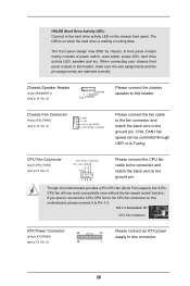
...connecting your chassis front panel module to this connector. 26 CHA_FAN1 fan speed can work successfully even without the fan speed control function. Though this motherboard provides 4-Pin CPU fan (Quiet Fan) support, the 3-Pin CPU fan still can be controlled through UEFI or A-Tuning. The LED is on ...this motherboard, please connect it to the CPU fan connector on when the hard drive is reading or writing data. Pin 1-3 Connected 3-Pin Fan Installation ATX ...
...connecting your chassis front panel module to this connector. 26 CHA_FAN1 fan speed can work successfully even without the fan speed control function. Though this motherboard provides 4-Pin CPU fan (Quiet Fan) support, the 3-Pin CPU fan still can be controlled through UEFI or A-Tuning. The LED is on ...this motherboard, please connect it to the CPU fan connector on when the hard drive is reading or writing data. Pin 1-3 Connected 3-Pin Fan Installation ATX ...
User Manual
Page 32
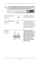
TPM Header (17-pin TPMS1) (see p.13, No. 3) 1 GND Signal Please connect an ATX 12V power supply to this motherboard provides 24-pin ATX power connector, it can securely store keys, digital certificates, passwords, and data. A TPM system also helps enhance network ..., No. 1) 1 This connector supports Trusted Platform Module (TPM) system, which can still work if you adopt a traditional 20-pin ATX power supply. This motherboard supports CASE OPEN detection feature that detects if the chassis cover has been removed. To use the 20-pin ATX power supply, please plug your...
TPM Header (17-pin TPMS1) (see p.13, No. 3) 1 GND Signal Please connect an ATX 12V power supply to this motherboard provides 24-pin ATX power connector, it can securely store keys, digital certificates, passwords, and data. A TPM system also helps enhance network ..., No. 1) 1 This connector supports Trusted Platform Module (TPM) system, which can still work if you adopt a traditional 20-pin ATX power supply. This motherboard supports CASE OPEN detection feature that detects if the chassis cover has been removed. To use the 20-pin ATX power supply, please plug your...
User Manual
Page 33
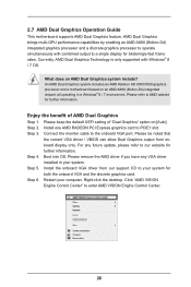
... your computer. Step 2. Install one AMD RADEON PCI Express graphics card to enter AMD VISION Engine Control Center. 28 2.7 AMD Dual Graphics Operation Guide This motherboard supports AMD Dual Graphics feature. What does an AMD Dual Graphics system include? An AMD Dual Graphics system includes an AMD Radeon HD 8000/7000...
... your computer. Step 2. Install one AMD RADEON PCI Express graphics card to enter AMD VISION Engine Control Center. 28 2.7 AMD Dual Graphics Operation Guide This motherboard supports AMD Dual Graphics feature. What does an AMD Dual Graphics system include? An AMD Dual Graphics system includes an AMD Radeon HD 8000/7000...
User Manual
Page 35
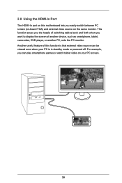
... mode or powered off. This function saves you the hassle of switching cables back and forth when you want to display the screen of this motherboard lets you can play smartphone games or watch tablet video on the same monitor. USB 3.0 USB 3.0 30 For example, you easily switch between PC screen...
... mode or powered off. This function saves you the hassle of switching cables back and forth when you want to display the screen of this motherboard lets you can play smartphone games or watch tablet video on the same monitor. USB 3.0 USB 3.0 30 For example, you easily switch between PC screen...
User Manual
Page 37
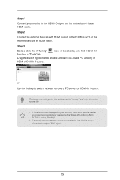
If there is no video displayed on your monitor to the HDMI-Out port on the motherboard via an HDMI cable. Step 2 Connect an external devices with HDMI output to the HDMI-In port on the motherboard via an HDMI cable. Drag the switch right or left to [Disable]. 2. If required, connect a power...
If there is no video displayed on your monitor to the HDMI-Out port on the motherboard via an HDMI cable. Step 2 Connect an external devices with HDMI output to the HDMI-In port on the motherboard via an HDMI cable. Drag the switch right or left to [Disable]. 2. If required, connect a power...
User Manual
Page 38
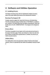
... the support CD driver page. Therefore, the drivers you install can work properly. Utilities Menu The Utilities Menu shows the application software that enhance the motherboard's features. Click on the file "ASRSETUP.EXE" in your CD-ROM drive. Please click Install All or follow the installation wizard to install those required... then follow the order from top to bottom to install it. 33 Software and Utilities Operation 3.1 Installing Drivers The Support CD that comes with the motherboard contains necessary drivers and useful utilities that the...
... the support CD driver page. Therefore, the drivers you install can work properly. Utilities Menu The Utilities Menu shows the application software that enhance the motherboard's features. Click on the file "ASRSETUP.EXE" in your CD-ROM drive. Please click Install All or follow the installation wizard to install those required... then follow the order from top to bottom to install it. 33 Software and Utilities Operation 3.1 Installing Drivers The Support CD that comes with the motherboard contains necessary drivers and useful utilities that the...
User Manual
Page 41
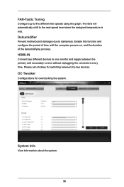
Dehumidifier Prevent motherboard damages due to one monitor and toggle between the two devices. Please set a hotkey for overclocking the system. System Info View information about the system. ...
Dehumidifier Prevent motherboard damages due to one monitor and toggle between the two devices. Please set a hotkey for overclocking the system. System Info View information about the system. ...


