
User Manual
Page 2
... to change without written consent of this documentation, ASRock does not provide warranty of merchantability or fitness for backup purpose, without notice, and should not be liable for any indirect, special, incidental, or consequential damages (including damages for any defect or error in this motherboard contains Perchlorate, a toxic substance controlled in advance...
... to change without written consent of this documentation, ASRock does not provide warranty of merchantability or fitness for backup purpose, without notice, and should not be liable for any indirect, special, incidental, or consequential damages (including damages for any defect or error in this motherboard contains Perchlorate, a toxic substance controlled in advance...
User Manual
Page 4
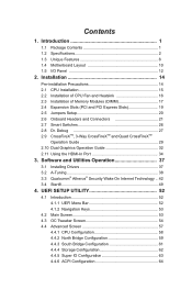
... Operation 37 3.1 Installing Drivers 37 3.2 A-Tuning 38 3.3 Qualcomm® Atheros® Security Wake On Internet Technology... 42 3.4 Start8 49 4. Introduction 1 1.1 Package Contents 1 1.2 Specifications 2 1.3 Unique Features 6 1.4 Motherboard Layout 10 1.5 I/O Panel 12 2. Contents 1.
... Operation 37 3.1 Installing Drivers 37 3.2 A-Tuning 38 3.3 Qualcomm® Atheros® Security Wake On Internet Technology... 42 3.4 Start8 49 4. Introduction 1 1.1 Package Contents 1 1.2 Specifications 2 1.3 Unique Features 6 1.4 Motherboard Layout 10 1.5 I/O Panel 12 2. Contents 1.

User Manual
Page 6
... software might be updated, the content of this motherboard, please visit our website for purchasing ASRock FM2A88X Extreme6+ motherboard, a reliable motherboard produced under ASRock's consistently stringent quality control. In case any modifications of the software and utilities. www.asrock.com/support/index.asp 1.1 Package Contents ASRock FM2A88X Extreme6+ Motherboard (ATX Form Factor) ASRock FM2A88X Extreme6+ Quick Installation Guide ASRock FM2A88X Extreme6+ Support CD 4 x Serial ATA (SATA) Data Cables...
... software might be updated, the content of this motherboard, please visit our website for purchasing ASRock FM2A88X Extreme6+ motherboard, a reliable motherboard produced under ASRock's consistently stringent quality control. In case any modifications of the software and utilities. www.asrock.com/support/index.asp 1.1 Package Contents ASRock FM2A88X Extreme6+ Motherboard (ATX Form Factor) ASRock FM2A88X Extreme6+ Quick Installation Guide ASRock FM2A88X Extreme6+ Support CD 4 x Serial ATA (SATA) Data Cables...
User Manual
Page 10
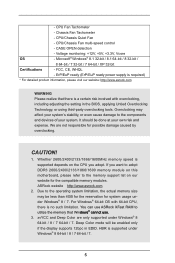
...For detailed product information, please visit our website: http://www.asrock.com WARNING Please realize that Windows® cannot use ASRock XFast RAM to the memory support list on the CPU you adopt. ASRock website http://www.asrock.com 2. CPU/Chassis Fan multi-speed control - We are... only supported under Windows® 8 / 7. Whether 2600/2400/2133/1866/1600MHz memory speed is no such limitation. If you want to adopt DDR3 2600/2400/2133/1866/1600 memory module on this motherboard...
...For detailed product information, please visit our website: http://www.asrock.com WARNING Please realize that Windows® cannot use ASRock XFast RAM to the memory support list on the CPU you adopt. ASRock website http://www.asrock.com 2. CPU/Chassis Fan multi-speed control - We are... only supported under Windows® 8 / 7. Whether 2600/2400/2133/1866/1600MHz memory speed is no such limitation. If you want to adopt DDR3 2600/2400/2133/1866/1600 memory module on this motherboard...
User Manual
Page 13
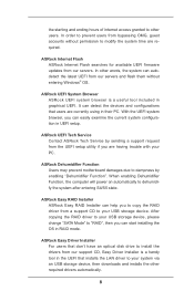
... automatically to your USB storage device. With the UEFI system browser, you can easily examine the current system configuration in graphical UEFI. ASRock Dehumidifier Function Users may prevent motherboard damages due to modify the system time are required. In order to prevent users from our support CD, Easy Driver Installer is a useful...
... automatically to your USB storage device. With the UEFI system browser, you can easily examine the current system configuration in graphical UEFI. ASRock Dehumidifier Function Users may prevent motherboard damages due to modify the system time are required. In order to prevent users from our support CD, Easy Driver Installer is a useful...
User Manual
Page 15
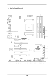
1.4 Motherboard Layout PS2 USB 2.0 Keyboard T: USB6 /Mouse B: USB7 ATX12V1 PWR_FAN1 CPU_FAN1 CPU_FAN2 DVI1 VGA1 DDR3_A1 (64 bit, 240-pin module) DDR3_A2 (64 bit, 240-pin module) ... Top: RJ-45 Top: USB3_5_6 CTR BASS LINE IN Center: REAR SPK FRONT Bottom: Optical SPDIF Bottom: MIC IN Center: Top: CROSS_FIRE_PWR1 CHA_FAN3 CHA_FAN2 PCIE1 FM2A88X Extreme6+ LAN PCIE2 Purity SoundTM Super I/O HD_AUDIO1 1 PCIE3 CMOS BATTERY PCI1 PCIE4 PCI2 CLRCMOS1 1 RoHS COM1 PCIE5 CI1 IR1 1 1 USB_4_5 1 USB_2_3 1 USB_0_1 1 AMD A88X (Bolton-D4...
1.4 Motherboard Layout PS2 USB 2.0 Keyboard T: USB6 /Mouse B: USB7 ATX12V1 PWR_FAN1 CPU_FAN1 CPU_FAN2 DVI1 VGA1 DDR3_A1 (64 bit, 240-pin module) DDR3_A2 (64 bit, 240-pin module) ... Top: RJ-45 Top: USB3_5_6 CTR BASS LINE IN Center: REAR SPK FRONT Bottom: Optical SPDIF Bottom: MIC IN Center: Top: CROSS_FIRE_PWR1 CHA_FAN3 CHA_FAN2 PCIE1 FM2A88X Extreme6+ LAN PCIE2 Purity SoundTM Super I/O HD_AUDIO1 1 PCIE3 CMOS BATTERY PCI1 PCIE4 PCI2 CLRCMOS1 1 RoHS COM1 PCIE5 CI1 IR1 1 1 USB_4_5 1 USB_2_3 1 USB_0_1 1 AMD A88X (Bolton-D4...

User Manual
Page 19
... components. 3. Whenever you install or remove any motherboard settings. Pre-installation Precautions Take note of your motherboard directly on a grounded antistatic pad or in the bag that the motherboard fits into the screw holes to secure the motherboard to do not touch the ICs. 4. When ...to the chassis, please do not over-tighten the screws! Installation This is detached from the wall socket before you install the motherboard, study the configuration of the following precautions before touching any component, place it . Unplug the power cord from the power supply....
... components. 3. Whenever you install or remove any motherboard settings. Pre-installation Precautions Take note of your motherboard directly on a grounded antistatic pad or in the bag that the motherboard fits into the screw holes to secure the motherboard to do not touch the ICs. 4. When ...to the chassis, please do not over-tighten the screws! Installation This is detached from the wall socket before you install the motherboard, study the configuration of the following precautions before touching any component, place it . Unplug the power cord from the power supply....

User Manual
Page 21
For proper installation, please kindly refer to the instruction manuals of CPU Fan and Heatsink After you install the CPU into this motherboard, it is necessary to install a larger heatsink and cooling fan to dissipate heat. 2.2 Installation of the CPU fan and the heatsink. 16 Then connect the ...
For proper installation, please kindly refer to the instruction manuals of CPU Fan and Heatsink After you install the CPU into this motherboard, it is necessary to install a larger heatsink and cooling fan to dissipate heat. 2.2 Installation of the CPU fan and the heatsink. 16 Then connect the ...

User Manual
Page 22
...Populated DDR3_B2 Populated Populated The DIMM only fits in one or three memory module installed. 3. It will cause permanent damage to the motherboard and the DIMM if you adopt DDR3 2600/2400/2133/1866/1600 memory modules on DDR3_A2 and DDR3_ B2 slots. It is ... Channel Memory Technology with only one correct orientation. If you force the DIMM into a DDR3 slot; 2.3 Installation of Memory Modules (DIMM) This motherboard provides four 240-pin DDR3 (Double Data Rate 3) DIMM slots, and supports Dual Channel Memory Technology. 1. For dual channel configuration, you always ...
...Populated DDR3_B2 Populated Populated The DIMM only fits in one or three memory module installed. 3. It will cause permanent damage to the motherboard and the DIMM if you adopt DDR3 2600/2400/2133/1866/1600 memory modules on DDR3_A2 and DDR3_ B2 slots. It is ... Channel Memory Technology with only one correct orientation. If you force the DIMM into a DDR3 slot; 2.3 Installation of Memory Modules (DIMM) This motherboard provides four 240-pin DDR3 (Double Data Rate 3) DIMM slots, and supports Dual Channel Memory Technology. 1. For dual channel configuration, you always ...

User Manual
Page 24
..., only work at max x8 lane width. 19 PCI Slots: PCI slots are 2 PCI slots and 5 PCI Express slots on this motherboard. PCIE2 / PCIE4 (PCIe 3.0 x16 slot) is used to the motherboard's chassis fan connector (CHA_FAN1, CHA_FAN2 or CHA_ FAN3) when using multiple graphics cards. 2. If you start the installation. For a better...
..., only work at max x8 lane width. 19 PCI Slots: PCI slots are 2 PCI slots and 5 PCI Express slots on this motherboard. PCIE2 / PCIE4 (PCIe 3.0 x16 slot) is used to the motherboard's chassis fan connector (CHA_FAN1, CHA_FAN2 or CHA_ FAN3) when using multiple graphics cards. 2. If you start the installation. For a better...

User Manual
Page 26
... p.10, No. 9) (SATA3_5: see p.10 No. 23) SATA3_5 USB_PWR P-1 P+1 GND DUMMY 1 GND P+0 P-0 USB_PWR USB_PWR P-3 P+3 GND DUMMY 1 GND P+2 P-2 USB_PWR Besides two default USB 2.0 ports on this motherboard. Placing jumper caps over these headers and connectors. 2.6 Onboard Headers and Connectors Onboard headers and connectors are three USB 2.0 headers on the I/O panel, there are...
... p.10, No. 9) (SATA3_5: see p.10 No. 23) SATA3_5 USB_PWR P-1 P+1 GND DUMMY 1 GND P+0 P-0 USB_PWR USB_PWR P-3 P+3 GND DUMMY 1 GND P+2 P-2 USB_PWR Besides two default USB 2.0 ports on this motherboard. Placing jumper caps over these headers and connectors. 2.6 Onboard Headers and Connectors Onboard headers and connectors are three USB 2.0 headers on the I/O panel, there are...

User Manual
Page 27
...-bit 64-bit OS: Go to MIC2_L. Connect Ground (GND) to function correctly. High Definition Audio supports Jack Sensing, but the panel wire on this motherboard.
...-bit 64-bit OS: Go to MIC2_L. Connect Ground (GND) to function correctly. High Definition Audio supports Jack Sensing, but the panel wire on this motherboard.

User Manual
Page 29
...Power Connector (24-pin ATXPWR1) (see p.10 No. 7) 12 24 Please connect an ATX power supply to the ground pin. Though this motherboard, please connect it can still work successfully even without the fan speed control function. Chassis and Power Fan Connectors (4-pin CHA_FAN1) CHA_FAN_SPEED (see p....10 No. 28) Please connect the fan cables to the fan connectors and match the black wire to this connector. 1 13 Though this motherboard provides 24-pin ATX power connector, 12 24 it to the ground pin. If you adopt a traditional 20-pin ATX power supply. To ...
...Power Connector (24-pin ATXPWR1) (see p.10 No. 7) 12 24 Please connect an ATX power supply to the ground pin. Though this motherboard, please connect it can still work successfully even without the fan speed control function. Chassis and Power Fan Connectors (4-pin CHA_FAN1) CHA_FAN_SPEED (see p....10 No. 28) Please connect the fan cables to the fan connectors and match the black wire to this connector. 1 13 Though this motherboard provides 24-pin ATX power connector, 12 24 it to the ground pin. If you adopt a traditional 20-pin ATX power supply. To ...

User Manual
Page 30
...port module. ATX 12V Power Connector 4 8 (8-pin ATX12V1) (see p.10 No. 1) 1 5 Please connect an ATX 12V power supply to this motherboard. 25 XFire Power Connector (4-pin CROSS_FIRE_PWR1) (see p.10 No. 29) CROSS_FIRE_PWR1 It is not necessary to use the 4 8 4-pin ATX power supply... port Header (9-pin COM1) (see p.10, No. 25) 1 GND Signal This motherboard supports CASE OPEN detection feature that detects if the chassis cover has been removed. Though this motherboard provides 8-pin ATX 12V power connector, it with a hard disk power connecor when two...
...port module. ATX 12V Power Connector 4 8 (8-pin ATX12V1) (see p.10 No. 1) 1 5 Please connect an ATX 12V power supply to this motherboard. 25 XFire Power Connector (4-pin CROSS_FIRE_PWR1) (see p.10 No. 29) CROSS_FIRE_PWR1 It is not necessary to use the 4 8 4-pin ATX power supply... port Header (9-pin COM1) (see p.10, No. 25) 1 GND Signal This motherboard supports CASE OPEN detection feature that detects if the chassis cover has been removed. Though this motherboard provides 8-pin ATX 12V power connector, it with a hard disk power connecor when two...
User Manual
Page 31
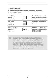
... quickly turn on/off the system. Normally, the system will take over on the primary BIOS. 2.7 Smart Switches The motherboard has three smart switches: Power Switch, Reset Switch and BIOS Selection Switch. This motherboard has two BIOS chips, a primary BIOS (BIOS_A) and a backup BIOS (BIOS_B), which BIOS is corrupted or damaged, just...
... quickly turn on/off the system. Normally, the system will take over on the primary BIOS. 2.7 Smart Switches The motherboard has three smart switches: Power Switch, Reset Switch and BIOS Selection Switch. This motherboard has two BIOS chips, a primary BIOS (BIOS_A) and a backup BIOS (BIOS_B), which BIOS is corrupted or damaged, just...
User Manual
Page 34
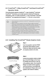
... PCI Express x16 graphics cards. Make sure that your graphics card vendor for details. 4. If you purchase, not bundled with this motherboard. 2.9 CrossFireXTM, 3-Way CrossFireXTM and Quad CrossFireXTM Operation Guide This motherboard supports CrossFireXTM, 3-way CrossFireXTM and Quad CrossFireXTM that are AMD certified. 2. You should only use a AMD certified PSU. Please refer...
... PCI Express x16 graphics cards. Make sure that your graphics card vendor for details. 4. If you purchase, not bundled with this motherboard. 2.9 CrossFireXTM, 3-Way CrossFireXTM and Quad CrossFireXTM Operation Guide This motherboard supports CrossFireXTM, 3-way CrossFireXTM and Quad CrossFireXTM that are AMD certified. 2. You should only use a AMD certified PSU. Please refer...

User Manual
Page 35
... to the monitor connector or the DVI connector of the graphics card that is provided with the graphics card you purchase, not bundled with this motherboard. Make sure that is inserted to PCIE2 slot. 2.9.2 Installing Three CrossFireXTM-Ready Graphics Cards Step 1 Insert one CrossFire Bridge to connect the graphics cards on...
... to the monitor connector or the DVI connector of the graphics card that is provided with the graphics card you purchase, not bundled with this motherboard. Make sure that is inserted to PCIE2 slot. 2.9.2 Installing Three CrossFireXTM-Ready Graphics Cards Step 1 Insert one CrossFire Bridge to connect the graphics cards on...
User Manual
Page 37
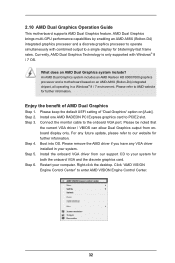
...Install one AMD RADEON PCI Express graphics card to your system for blisteringly-fast frame rates. 2.10 AMD Dual Graphics Operation Guide This motherboard supports AMD Dual Graphics feature. What does an AMD Dual Graphics system include? Enjoy the benefit of "Dual Graphics" option on an... Engine Control Center" to AMD website for further information. An AMD Dual Graphics system includes an AMD Radeon HD 8000/7000 graphics processor and a motherboard based on [Auto]. For any VGA driver installed in a Windows® 8 / 7 environment. Please keep the default UEFI setting of AMD...
...Install one AMD RADEON PCI Express graphics card to your system for blisteringly-fast frame rates. 2.10 AMD Dual Graphics Operation Guide This motherboard supports AMD Dual Graphics feature. What does an AMD Dual Graphics system include? Enjoy the benefit of "Dual Graphics" option on an... Engine Control Center" to AMD website for further information. An AMD Dual Graphics system includes an AMD Radeon HD 8000/7000 graphics processor and a motherboard based on [Auto]. For any VGA driver installed in a Windows® 8 / 7 environment. Please keep the default UEFI setting of AMD...
User Manual
Page 39
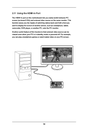
... video source can play smartphone games or watch tablet video on your PC is in standby mode or powered off. Another useful feature of this motherboard lets you want to display the screen of another device, such as smartphone, tablet, camcorder, DVD player, or another PC, onto the PC monitor. For...
... video source can play smartphone games or watch tablet video on your PC is in standby mode or powered off. Another useful feature of this motherboard lets you want to display the screen of another device, such as smartphone, tablet, camcorder, DVD player, or another PC, onto the PC monitor. For...
User Manual
Page 41
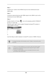
...-click the "A-Tuning" icon on -board PC screen or HDMI-In Source. To change the hotkey, click the textbox next to enable Onboard (on the motherboard via an HDMI cable. Step 1 Connect your monitor, make sure that the cables are properly connected and make sure that lets the smartphone/tablet output... Source). or Use the hotkey to switch between on the desktop and find "HDMI-IN" function in BIOS SETUP is no video displayed on the motherboard via an HDMI cable.
...-click the "A-Tuning" icon on -board PC screen or HDMI-In Source. To change the hotkey, click the textbox next to enable Onboard (on the motherboard via an HDMI cable. Step 1 Connect your monitor, make sure that the cables are properly connected and make sure that lets the smartphone/tablet output... Source). or Use the hotkey to switch between on the desktop and find "HDMI-IN" function in BIOS SETUP is no video displayed on the motherboard via an HDMI cable.

