
User Manual
Page 2
... as a commitment by any errors or omissions that may apply, see www.dtsc.ca.gov/hazardouswaste/perchlorate" ASRock Website: http://www.asrock.com Disclaimer: Specifications and information contained in the documentation or product. When you discard the Lithium battery in ...infringe. Version 1.0 Published August 2013 Copyright©2013 ASRock INC. Products and corporate names appearing in this motherboard contains Perchlorate, a toxic substance controlled in the United States and other countries. ASRock assumes no event shall ASRock, its directors, officers, employees, or agents be ...
... as a commitment by any errors or omissions that may apply, see www.dtsc.ca.gov/hazardouswaste/perchlorate" ASRock Website: http://www.asrock.com Disclaimer: Specifications and information contained in the documentation or product. When you discard the Lithium battery in ...infringe. Version 1.0 Published August 2013 Copyright©2013 ASRock INC. Products and corporate names appearing in this motherboard contains Perchlorate, a toxic substance controlled in the United States and other countries. ASRock assumes no event shall ASRock, its directors, officers, employees, or agents be ...

User Manual
Page 3
... 21 2.6 Onboard Headers and Connectors 22 2.7 CrossFireXTM and Quad CrossFireXTM Operation Guide 27 2.8 Dual Graphics Operation Guide 30 3. Contents 1. Introduction 1 1.1 Package Contents 1 1.2 Specifications 2 1.3 Unique Features 6 1.4 Motherboard Layout 11 1.5 I/O Panel 13 2.
... 21 2.6 Onboard Headers and Connectors 22 2.7 CrossFireXTM and Quad CrossFireXTM Operation Guide 27 2.8 Dual Graphics Operation Guide 30 3. Contents 1. Introduction 1 1.1 Package Contents 1 1.2 Specifications 2 1.3 Unique Features 6 1.4 Motherboard Layout 11 1.5 I/O Panel 13 2.

User Manual
Page 5
... of the BIOS setup. In this documentation, Chapter 1 and 2 contains the introduction of this motherboard, please visit our website for purchasing ASRock FM2A88X Extreme4+ motherboard, a reliable motherboard produced under ASRock's consistently stringent quality control. www.asrock.com/support/index.asp 1.1 Package Contents ASRock FM2A88X Extreme4+ Motherboard (ATX Form Factor) ASRock FM2A88X Extreme4+ Quick Installation Guide ASRock FM2A88X Extreme4+ Support CD 4 x Serial ATA (SATA) Data Cables (Optional) 1 x I/O Panel Shield...
... of the BIOS setup. In this documentation, Chapter 1 and 2 contains the introduction of this motherboard, please visit our website for purchasing ASRock FM2A88X Extreme4+ motherboard, a reliable motherboard produced under ASRock's consistently stringent quality control. www.asrock.com/support/index.asp 1.1 Package Contents ASRock FM2A88X Extreme4+ Motherboard (ATX Form Factor) ASRock FM2A88X Extreme4+ Quick Installation Guide ASRock FM2A88X Extreme4+ Support CD 4 x Serial ATA (SATA) Data Cables (Optional) 1 x I/O Panel Shield...

User Manual
Page 9
... the CPU you want to adopt DDR3 2600/2400/2133/1866/1600 memory module on this motherboard, please refer to utilize the memory that Windows® cannot use. 3. ASRock website http://www.asrock.com 2. You can use ASRock XFast RAM to the memory support list on our website for system usage under Windows®...
... the CPU you want to adopt DDR3 2600/2400/2133/1866/1600 memory module on this motherboard, please refer to utilize the memory that Windows® cannot use. 3. ASRock website http://www.asrock.com 2. You can use ASRock XFast RAM to the memory support list on our website for system usage under Windows®...

User Manual
Page 12
...the UEFI setup utility if you can easily examine the current system configuration in ACPI S5 mode)! ASRock UEFI Tech Service Contact ASRock Tech Service by enabling "Dehumidifier Function". This motherboard also provides a free 3.5mm audio cable (optional) that users are required. It can detect ...them without permission to dehumidify the system after entering S4/S5 state. 8 ASRock UEFI System Browser ASRock UEFI system browser is turned off (or in UEFI setup. ASRock Dehumidifier Function Users may prevent motherboard damages due to your PC. With the UEFI system browser, you are...
...the UEFI setup utility if you can easily examine the current system configuration in ACPI S5 mode)! ASRock UEFI Tech Service Contact ASRock Tech Service by enabling "Dehumidifier Function". This motherboard also provides a free 3.5mm audio cable (optional) that users are required. It can detect ...them without permission to dehumidify the system after entering S4/S5 state. 8 ASRock UEFI System Browser ASRock UEFI system browser is turned off (or in UEFI setup. ASRock Dehumidifier Function Users may prevent motherboard damages due to your PC. With the UEFI system browser, you are...
User Manual
Page 15
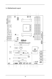
1.4 Motherboard Layout PS2 Keyboard/ Mouse HDMI1 Clr CMOS Bottom: Optical SPDIF Bottom: MIC IN USB 2.0 T: USB1 B: USB2 PWR_FAN1 ATX12V1 CPU_FAN1 CPU_FAN2 DVI1 VGA1 Fast RAM X DDR3_A1 (...-45 X Fast LAN Top: CTR BASS LINE IN Center: REAR SPK FRONT LAN Super I/O AUDIO CODEC HD_AUDIO1 1 Center: Top: USB3_9_10 CHA_FAN3 CHA_FAN2 PCIE1 PCI Express 3.0 FM2A88X Extreme4+ PCIE2 PCIE3 CMOS BATTERY PCI1 Front USB 3.0 X Fast USB CLRCMOS1 1 PCIE4 AMD A88X (Bolton-D4) Chipset CI1 1 1 TPMS1 PCI2 RoHS 64Mb BIOS PCI3 COM1 1 USB_11_12...
1.4 Motherboard Layout PS2 Keyboard/ Mouse HDMI1 Clr CMOS Bottom: Optical SPDIF Bottom: MIC IN USB 2.0 T: USB1 B: USB2 PWR_FAN1 ATX12V1 CPU_FAN1 CPU_FAN2 DVI1 VGA1 Fast RAM X DDR3_A1 (...-45 X Fast LAN Top: CTR BASS LINE IN Center: REAR SPK FRONT LAN Super I/O AUDIO CODEC HD_AUDIO1 1 Center: Top: USB3_9_10 CHA_FAN3 CHA_FAN2 PCIE1 PCI Express 3.0 FM2A88X Extreme4+ PCIE2 PCIE3 CMOS BATTERY PCI1 Front USB 3.0 X Fast USB CLRCMOS1 1 PCIE4 AMD A88X (Bolton-D4) Chipset CI1 1 1 TPMS1 PCI2 RoHS 64Mb BIOS PCI3 COM1 1 USB_11_12...

User Manual
Page 19
... any component, ensure that the power is switched off or the power cord is an ATX form factor motherboard. Installation This is detached from the wall socket before touching any motherboard settings. Unplug the power cord from the power supply. When placing screws into it on the carpet or... the like. Pre-installation Precautions Take note of your motherboard directly on a grounded antistatic pad or in the bag that the motherboard fits into the screw holes to secure the motherboard to do not touch the ICs. 4. Hold components by the edges and do ...
... any component, ensure that the power is switched off or the power cord is an ATX form factor motherboard. Installation This is detached from the wall socket before touching any motherboard settings. Unplug the power cord from the power supply. When placing screws into it on the carpet or... the like. Pre-installation Precautions Take note of your motherboard directly on a grounded antistatic pad or in the bag that the motherboard fits into the screw holes to secure the motherboard to do not touch the ICs. 4. Hold components by the edges and do ...

User Manual
Page 21
... the heatsink. 17 For proper installation, please kindly refer to the instruction manuals of CPU Fan and Heatsink After you install the CPU into this motherboard, it is necessary to install a larger heatsink and cooling fan to dissipate heat. Make sure that the CPU and the heatsink are securely fastened and...
... the heatsink. 17 For proper installation, please kindly refer to the instruction manuals of CPU Fan and Heatsink After you install the CPU into this motherboard, it is necessary to install a larger heatsink and cooling fan to dissipate heat. Make sure that the CPU and the heatsink are securely fastened and...

User Manual
Page 22
...and supports Dual Channel Memory Technology. 1. If you force the DIMM into a DDR3 slot; For dual channel configuration, you always need to the motherboard and the DIMM if you adopt DDR3 2600/2400/2133/1866/1600 memory modules on DDR3_A2 and DDR3_ B2 slots. It is unable to activate... Dual Channel Memory Technology with only one correct orientation. otherwise, this motherboard, it is not allowed to install them on this motherboard and DIMM may be damaged. 4. It is recommended to install a DDR or DDR2 memory module into the slot...
...and supports Dual Channel Memory Technology. 1. If you force the DIMM into a DDR3 slot; For dual channel configuration, you always need to the motherboard and the DIMM if you adopt DDR3 2600/2400/2133/1866/1600 memory modules on DDR3_A2 and DDR3_ B2 slots. It is unable to activate... Dual Channel Memory Technology with only one correct orientation. otherwise, this motherboard, it is not allowed to install them on this motherboard and DIMM may be damaged. 4. It is recommended to install a DDR or DDR2 memory module into the slot...

User Manual
Page 24
...thermal environment, please connect a chassis fan to install expansion cards that the power supply is switched off or the power cord is used to the motherboard's chassis fan connector (CHA_FAN1, CHA_FAN2 or CHA_FAN3) when using multiple graphics cards. 20 Before installing an expansion card, please make necessary hardware settings ...for PCI Express cards with x1 lane width cards. PCI Slots: PCI slots are 3 PCI slots and 4 PCI Express slots on this motherboard. 2.4 Expansion Slots (PCI and PCI Express Slots) There are used for the card before you start the installation.
...thermal environment, please connect a chassis fan to install expansion cards that the power supply is switched off or the power cord is used to the motherboard's chassis fan connector (CHA_FAN1, CHA_FAN2 or CHA_FAN3) when using multiple graphics cards. 20 Before installing an expansion card, please make necessary hardware settings ...for PCI Express cards with x1 lane width cards. PCI Slots: PCI slots are 3 PCI slots and 4 PCI Express slots on this motherboard. 2.4 Expansion Slots (PCI and PCI Express Slots) There are used for the card before you start the installation.

User Manual
Page 26
... DUMMY 1 GND P+15 P-15 USB_PWR Besides two default USB 2.0 ports on the I /O panel, there is one USB 3.0 header on this motherboard. 2.6 Onboard Headers and Connectors Onboard headers and connectors are three USB 2.0 headers on this motherboard. Do NOT place jumper caps over the headers and connectors will cause permanent damage of the...
... DUMMY 1 GND P+15 P-15 USB_PWR Besides two default USB 2.0 ports on the I /O panel, there is one USB 3.0 header on this motherboard. 2.6 Onboard Headers and Connectors Onboard headers and connectors are three USB 2.0 headers on this motherboard. Do NOT place jumper caps over the headers and connectors will cause permanent damage of the...

User Manual
Page 29
...Power Supply Installation 1 13 ATX 12V Power Connector 4 8 (8-pin ATX12V1) (see p.11 No. 2) 1 5 Please connect an ATX 12V power supply to this motherboard provides 8-pin ATX 12V power connector, it can still work if you adopt a traditional 4-pin ATX 12V power supply. (3-pin PWR_FAN1) (see p.11 No. ...pin CPU_FAN1) CPU_FAN_SPEED +12V (see p.11 No. 7) 12 24 Please connect an ATX power supply to this connector. 1 13 Though this motherboard provides 24-pin ATX power connector, 12 24 it to Pin 1-3. Though this connector. To use the 20-pin ATX power supply, please plug...
...Power Supply Installation 1 13 ATX 12V Power Connector 4 8 (8-pin ATX12V1) (see p.11 No. 2) 1 5 Please connect an ATX 12V power supply to this motherboard provides 8-pin ATX 12V power connector, it can still work if you adopt a traditional 4-pin ATX 12V power supply. (3-pin PWR_FAN1) (see p.11 No. ...pin CPU_FAN1) CPU_FAN_SPEED +12V (see p.11 No. 7) 12 24 Please connect an ATX power supply to this connector. 1 13 Though this motherboard provides 24-pin ATX power connector, 12 24 it to Pin 1-3. Though this connector. To use the 20-pin ATX power supply, please plug...

User Manual
Page 30
.... This feature requires a chassis with chassis intrusion detection design. A TPM system also helps enhance network security, protects digital identities, and ensures platform integrity. 26 This motherboard supports CASE OPEN detection feature that detects if the chassis cover has been removed.
.... This feature requires a chassis with chassis intrusion detection design. A TPM system also helps enhance network security, protects digital identities, and ensures platform integrity. 26 This motherboard supports CASE OPEN detection feature that detects if the chassis cover has been removed.

User Manual
Page 31
...CrossFireXTM cards may require different methods to the AMD's website for details. 4. If you pair a 12-pipe CrossFireXTM Edition card with this motherboard. Make sure that your system requires. Make sure that your power supply unit (PSU) can provide at least the minimum power your ...cards that are supported with Windows® 7 / 7 64-bit / 8 / 8 64-bit OS. 1. 2.7 CrossFireXTM and Quad CrossFireXTM Operation Guide This motherboard supports CrossFireXTM and Quad CrossFireXTM that allows you to install up to PCIE4 slot. You should only use a AMD certified PSU. Please refer to AMD...
...CrossFireXTM cards may require different methods to the AMD's website for details. 4. If you pair a 12-pipe CrossFireXTM Edition card with this motherboard. Make sure that your system requires. Make sure that your power supply unit (PSU) can provide at least the minimum power your ...cards that are supported with Windows® 7 / 7 64-bit / 8 / 8 64-bit OS. 1. 2.7 CrossFireXTM and Quad CrossFireXTM Operation Guide This motherboard supports CrossFireXTM and Quad CrossFireXTM that allows you to install up to PCIE4 slot. You should only use a AMD certified PSU. Please refer to AMD...

User Manual
Page 34
...installed in a Windows® 8 / 7 environment. Step 5. An AMD Dual Graphics system includes an AMD Radeon HD 8000/7000 graphics processor and a motherboard based on [Auto]. Step 3. Step 2. Boot into OS. Connect the monitor cable to PCIE2 slot. Step 4. Please remove the AMD driver if you... enter AMD VISION Engine Control Center. 30 Install the onboard VGA driver from onboard display only. 2.8 AMD Dual Graphics Operation Guide This motherboard supports AMD Dual Graphics feature. Enjoy the benefit of "Dual Graphics" option on an AMD A88X (Bolton-D4) integrated chipset, all...
...installed in a Windows® 8 / 7 environment. Step 5. An AMD Dual Graphics system includes an AMD Radeon HD 8000/7000 graphics processor and a motherboard based on [Auto]. Step 3. Step 2. Boot into OS. Connect the monitor cable to PCIE2 slot. Step 4. Please remove the AMD driver if you... enter AMD VISION Engine Control Center. 30 Install the onboard VGA driver from onboard display only. 2.8 AMD Dual Graphics Operation Guide This motherboard supports AMD Dual Graphics feature. Enjoy the benefit of "Dual Graphics" option on an AMD A88X (Bolton-D4) integrated chipset, all...

User Manual
Page 36
... your computer. Utilities Menu The Utilities Menu shows the application software that enhance the motherboard's features. Software and Utilities Operation 3.1 Installing Drivers The Support CD that comes with the motherboard contains necessary drivers and useful utilities that the motherboard supports. Therefore, the drivers you install can work properly. The CD automatically displays the...
... your computer. Utilities Menu The Utilities Menu shows the application software that enhance the motherboard's features. Software and Utilities Operation 3.1 Installing Drivers The Support CD that comes with the motherboard contains necessary drivers and useful utilities that the motherboard supports. Therefore, the drivers you install can work properly. The CD automatically displays the...

User Manual
Page 39
FAN-Tastic Tuning Configure up to dampness. Dehumidifier Prevent motherboard damages due to five different fan speeds using the graph. Enable this function and configure the period of time until the computer powers on, and the duration of the dehumidifying process. OC Tweaker Configurations for overclocking the system. System Info View information about the system. 35 The fans will automatically shift to the next speed level when the assigned temperature is met.
FAN-Tastic Tuning Configure up to dampness. Dehumidifier Prevent motherboard damages due to five different fan speeds using the graph. Enable this function and configure the period of time until the computer powers on, and the duration of the dehumidifying process. OC Tweaker Configurations for overclocking the system. System Info View information about the system. 35 The fans will automatically shift to the next speed level when the assigned temperature is met.
User Manual
Page 51
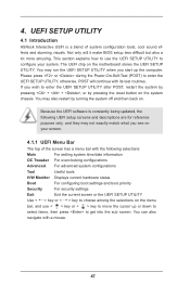
... button on the system chassis. This section explains how to use < > key or < > key to move the cursor up the computer. UEFI SETUP UTILITY 4.1 Introduction ASRock Interactive UEFI is constantly being updated, the following UEFI setup screens and descriptions are for reference purpose only, and they may run the UEFI SETUP... (POST) to enter the UEFI SETUP UTILITY after POST, restart the system by pressing + + , or by turning the system off and then back on the motherboard stores the UEFI SETUP UTILITY.
... button on the system chassis. This section explains how to use < > key or < > key to move the cursor up the computer. UEFI SETUP UTILITY 4.1 Introduction ASRock Interactive UEFI is constantly being updated, the following UEFI setup screens and descriptions are for reference purpose only, and they may run the UEFI SETUP... (POST) to enter the UEFI SETUP UTILITY after POST, restart the system by pressing + + , or by turning the system off and then back on the motherboard stores the UEFI SETUP UTILITY.

User Manual
Page 53
... to select Overclock Mode. Spread Spectrum This item should be noted that average power consumption over a thermally significant time period remains at your components and motherboard. Configuration options: [Enabled] and [Disabled]. EZ OC Mode You can set the item "Overclock Mode" to [Manual]. Configuration options: [Auto] and [Manual]. If [Enabled] is...
... to select Overclock Mode. Spread Spectrum This item should be noted that average power consumption over a thermally significant time period remains at your components and motherboard. Configuration options: [Enabled] and [Disabled]. EZ OC Mode You can set the item "Overclock Mode" to [Manual]. Configuration options: [Auto] and [Manual]. If [Enabled] is...

User Manual
Page 54
... to adjust the value of this item. Processor Maximum Voltage It will display Processor Maximum Voltage for safety and system stability, it is selected, the motherboard will display Processor Maximum Frequency for system stability. Boost Frequency Multiplier For safety and system stability, it is not recommended to [Manual], you may adjust...
... to adjust the value of this item. Processor Maximum Voltage It will display Processor Maximum Voltage for safety and system stability, it is selected, the motherboard will display Processor Maximum Frequency for system stability. Boost Frequency Multiplier For safety and system stability, it is not recommended to [Manual], you may adjust...

