
User Manual
Page 2
... is subject to change without written consent of this documentation may or may not be constructed as a commitment by ASRock. ASRock assumes no event shall ASRock, its directors, officers, employees, or agents be reproduced, transcribed, transmitted, or translated in any language, in ...be liable for any interference received, including interference that may cause undesired operation. This device complies with Part 15 of this motherboard contains Perchlorate, a toxic substance controlled in advance. When you discard the Lithium battery in California, USA, please follow ...
... is subject to change without written consent of this documentation may or may not be constructed as a commitment by ASRock. ASRock assumes no event shall ASRock, its directors, officers, employees, or agents be reproduced, transcribed, transmitted, or translated in any language, in ...be liable for any interference received, including interference that may cause undesired operation. This device complies with Part 15 of this motherboard contains Perchlorate, a toxic substance controlled in advance. When you discard the Lithium battery in California, USA, please follow ...
User Manual
Page 3
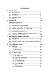
... Bridge Configuration 55 4.4.4 Storage Configuration 56 4.4.5 Super IO Configuration 57 4.4.6 ACPI Configuration 58 4.4.7 USB Configuration 60 4.4.8 Trusted Computing 61 Introduction 1 1.1 Package Contents 1 1.2 Specifications 2 1.3 Unique Features 6 1.4 Motherboard Layout 11 1.5 I/O Panel 13 2. Software and Utilities Operation 32 3.1 Installing Drivers 32 3.2 A-Tuning 33 3.3 Qualcomm® Atheros® Security Wake On Internet Technology... 37 3.4 Start8...
... Bridge Configuration 55 4.4.4 Storage Configuration 56 4.4.5 Super IO Configuration 57 4.4.6 ACPI Configuration 58 4.4.7 USB Configuration 60 4.4.8 Trusted Computing 61 Introduction 1 1.1 Package Contents 1 1.2 Specifications 2 1.3 Unique Features 6 1.4 Motherboard Layout 11 1.5 I/O Panel 13 2. Software and Utilities Operation 32 3.1 Installing Drivers 32 3.2 A-Tuning 33 3.3 Qualcomm® Atheros® Security Wake On Internet Technology... 37 3.4 Start8...

User Manual
Page 5
... AHCI mode. 1 In case any modifications of the motherboard and step-by-step installation guides. www.asrock.com/support/index.asp 1.1 Package Contents ASRock FM2A88M Extreme4+ Motherboard (Micro ATX Form Factor) ASRock FM2A88M Extreme4+ Quick Installation Guide ASRock FM2A88M Extreme4+ Support CD 2 x Serial ATA (SATA) Data Cables (Optional) 1 x I/O Panel Shield ASRock Reminds You... ASRock website http://www.asrock.com If you are using. Chapter 4 contains...
... AHCI mode. 1 In case any modifications of the motherboard and step-by-step installation guides. www.asrock.com/support/index.asp 1.1 Package Contents ASRock FM2A88M Extreme4+ Motherboard (Micro ATX Form Factor) ASRock FM2A88M Extreme4+ Quick Installation Guide ASRock FM2A88M Extreme4+ Support CD 2 x Serial ATA (SATA) Data Cables (Optional) 1 x I/O Panel Shield ASRock Reminds You... ASRock website http://www.asrock.com If you are using. Chapter 4 contains...

User Manual
Page 9
... you adopt. For Windows® 64-bit OS with 64-bit CPU, there is supported under Windows® 8 64-bit / 8 / 7 64-bit / 7. ASRock website http://www.asrock.com 2. Whether 2600/2400/2133/1866/1600MHz memory speed is supported depends on the CPU you want to adopt DDR3 2600/2400/2133/1866.../1600 memory module on this motherboard, please refer to the memory support list on our website for system usage under Windows® 8 / 7. Due to...
... you adopt. For Windows® 64-bit OS with 64-bit CPU, there is supported under Windows® 8 64-bit / 8 / 7 64-bit / 7. ASRock website http://www.asrock.com 2. Whether 2600/2400/2133/1866/1600MHz memory speed is supported depends on the CPU you want to adopt DDR3 2600/2400/2133/1866.../1600 memory module on this motherboard, please refer to the memory support list on our website for system usage under Windows® 8 / 7. Due to...

User Manual
Page 12
...easily examine the current system configuration in ACPI S5 mode)! This motherboard also provides a free 3.5mm audio cable (optional) that users are currently using in graphical UEFI. ASRock UEFI System Browser ASRock UEFI system browser is turned off (or in UEFI setup. With... Dehumidifier Function, the computer will power on automatically to dampness by sending a support request from our servers. ASRock Dehumidifier Function Users may prevent motherboard damages due to dehumidify the system after entering S4/S5 state. 8 It can detect the devices and configurations...
...easily examine the current system configuration in ACPI S5 mode)! This motherboard also provides a free 3.5mm audio cable (optional) that users are currently using in graphical UEFI. ASRock UEFI System Browser ASRock UEFI system browser is turned off (or in UEFI setup. With... Dehumidifier Function, the computer will power on automatically to dampness by sending a support request from our servers. ASRock Dehumidifier Function Users may prevent motherboard damages due to dehumidify the system after entering S4/S5 state. 8 It can detect the devices and configurations...
User Manual
Page 15
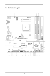
...-pin module) ATXPWR1 1.4 Motherboard Layout PS2 Keyboard/ Mouse USB 2.0 T: USB3 B: USB4 PWR_FAN1 ATX12V1 CPU_FAN1 CPU_FAN2 DVI1 VGA1 SOCKET FM2b HDMI1 Bottom: Optical SPDIF Bottom: MIC IN USB 3.0 T: USB1 B: USB2 USB 2.0 T: USB1 Top: B: USB2 RJ-45 Top: CTR BASS Center: REAR SPK Top: LINE IN Center: FRONT LAN CHA_FAN1 FM2A88M Extreme4+ PCIE1 Front USB...
...-pin module) ATXPWR1 1.4 Motherboard Layout PS2 Keyboard/ Mouse USB 2.0 T: USB3 B: USB4 PWR_FAN1 ATX12V1 CPU_FAN1 CPU_FAN2 DVI1 VGA1 SOCKET FM2b HDMI1 Bottom: Optical SPDIF Bottom: MIC IN USB 3.0 T: USB1 B: USB2 USB 2.0 T: USB1 Top: B: USB2 RJ-45 Top: CTR BASS Center: REAR SPK Top: LINE IN Center: FRONT LAN CHA_FAN1 FM2A88M Extreme4+ PCIE1 Front USB...

User Manual
Page 19
..., ensure that the power is switched off or the power cord is a Micro ATX form factor motherboard. Before you install or remove any component. 2. To avoid damaging the motherboard components due to static electricity, NEVER place your chassis to the chassis, please do not over-tighten... the screws! Before you uninstall any motherboard settings. Installation This is detached from the wall socket before you install motherboard components or change any component, place it on the carpet or the like. Whenever you install ...
..., ensure that the power is switched off or the power cord is a Micro ATX form factor motherboard. Before you install or remove any component. 2. To avoid damaging the motherboard components due to static electricity, NEVER place your chassis to the chassis, please do not over-tighten... the screws! Before you uninstall any motherboard settings. Installation This is detached from the wall socket before you install motherboard components or change any component, place it on the carpet or the like. Whenever you install ...

User Manual
Page 21
For proper installation, please kindly refer to the instruction manuals of CPU Fan and Heatsink After you install the CPU into this motherboard, it is necessary to install a larger heatsink and cooling fan to dissipate heat. 2.2 Installation of the CPU fan and the heatsink. 17 Make sure that ...
For proper installation, please kindly refer to the instruction manuals of CPU Fan and Heatsink After you install the CPU into this motherboard, it is necessary to install a larger heatsink and cooling fan to dissipate heat. 2.2 Installation of the CPU fan and the heatsink. 17 Make sure that ...

User Manual
Page 22
...the slot at incorrect orientation. 18 It will cause permanent damage to install them on this motherboard and DIMM may be damaged. 4. It is recommended to the motherboard and the DIMM if you adopt DDR3 2600/2400/2133/1866/1600 memory modules on DDR3_A2 ...Populated DDR3_A2 Populated Populated DDR3_B1 Populated Populated DDR3_B2 Populated Populated The DIMM only fits in one or three memory module installed. 3. otherwise, this motherboard, it is unable to install identical (the same brand, speed, size and chip-type) DDR3 DIMM pairs. 2. 2.3 Installation of Memory Modules ...
...the slot at incorrect orientation. 18 It will cause permanent damage to install them on this motherboard and DIMM may be damaged. 4. It is recommended to the motherboard and the DIMM if you adopt DDR3 2600/2400/2133/1866/1600 memory modules on DDR3_A2 ...Populated DDR3_A2 Populated Populated DDR3_B1 Populated Populated DDR3_B2 Populated Populated The DIMM only fits in one or three memory module installed. 3. otherwise, this motherboard, it is unable to install identical (the same brand, speed, size and chip-type) DDR3 DIMM pairs. 2. 2.3 Installation of Memory Modules ...

User Manual
Page 24
PCIE Slots: PCIE1 (PCIe 3.0 x16 slot) is used for PCI Express x16 lane width graphics cards. PCIE3 (PCIe 2.0 x16 slot) is used to the motherboard's chassis fan connector (CHA_FAN1) when using multiple graphics cards. 20 PCIE2 (PCIe 2.0 x1 slot) is used for PCI Express x4 lane width graphics cards. Before ... fan to install expansion cards that the power supply is switched off or the power cord is 1 PCI slot and 3 PCI Express slots on this motherboard. 2.4 Expansion Slots (PCI and PCI Express Slots) There is unplugged.
PCIE Slots: PCIE1 (PCIe 3.0 x16 slot) is used for PCI Express x16 lane width graphics cards. PCIE3 (PCIe 2.0 x16 slot) is used to the motherboard's chassis fan connector (CHA_FAN1) when using multiple graphics cards. 20 PCIE2 (PCIe 2.0 x1 slot) is used for PCI Express x4 lane width graphics cards. Before ... fan to install expansion cards that the power supply is switched off or the power cord is 1 PCI slot and 3 PCI Express slots on this motherboard. 2.4 Expansion Slots (PCI and PCI Express Slots) There is unplugged.

User Manual
Page 26
...USB_PWR P-10 P+10 GND DUMMY 1 GND P+9 P-9 USB_PWR Besides four default USB 2.0 ports on the I /O panel, there is one USB 3.0 header on this motherboard. This USB 3.0 header can support two USB 2.0 ports. The current SATA3 interface allows up to 6.0 Gb/s data transfer rate. USB 3.0 Header (19-pin ...SATA data cables for internal storage devices. Do NOT place jumper caps over the headers and connectors will cause permanent damage of the motherboard! Placing jumper caps over these headers and connectors. Each USB 2.0 header can support two USB 3.0 ports. 22 2.6 Onboard Headers ...
...USB_PWR P-10 P+10 GND DUMMY 1 GND P+9 P-9 USB_PWR Besides four default USB 2.0 ports on the I /O panel, there is one USB 3.0 header on this motherboard. This USB 3.0 header can support two USB 2.0 ports. The current SATA3 interface allows up to 6.0 Gb/s data transfer rate. USB 3.0 Header (19-pin ...SATA data cables for internal storage devices. Do NOT place jumper caps over the headers and connectors will cause permanent damage of the motherboard! Placing jumper caps over these headers and connectors. Each USB 2.0 header can support two USB 3.0 ports. 22 2.6 Onboard Headers ...

User Manual
Page 29
... 12V Power Connector 4 8 (8-pin ATX12V1) (see p.11 No. 2) 1 5 Please connect an ATX 12V power supply to the ground pin. Though this motherboard provides 24-pin ATX power connector, 12 24 it can work if you adopt a traditional 20-pin ATX power supply. Pin 1-3 Connected 3-Pin Fan Installation... to Pin 1-3. If you plan to connect the 3-Pin CPU fan to the CPU fan connector on this motherboard, please connect it to this connector. 1 13 Though this motherboard provides 4-Pin CPU fan (Quiet Fan) support, the 3-Pin CPU fan still can still work successfully even ...
... 12V Power Connector 4 8 (8-pin ATX12V1) (see p.11 No. 2) 1 5 Please connect an ATX 12V power supply to the ground pin. Though this motherboard provides 24-pin ATX power connector, 12 24 it can work if you adopt a traditional 20-pin ATX power supply. Pin 1-3 Connected 3-Pin Fan Installation... to Pin 1-3. If you plan to connect the 3-Pin CPU fan to the CPU fan connector on this motherboard, please connect it to this connector. 1 13 Though this motherboard provides 4-Pin CPU fan (Quiet Fan) support, the 3-Pin CPU fan still can still work successfully even ...

User Manual
Page 30
... Module (TPM) system, which can securely store keys, digital certificates, passwords, and data. Serial port Header (9-pin COM1) (see p.11, No. 29) 1 GND Signal This motherboard supports CASE OPEN detection feature that allows convenient connection of printer devices. Chassis Intrusion Header (2-pin CI1) (see p.11 No. 26) This COM1 header supports...
... Module (TPM) system, which can securely store keys, digital certificates, passwords, and data. Serial port Header (9-pin COM1) (see p.11, No. 29) 1 GND Signal This motherboard supports CASE OPEN detection feature that allows convenient connection of printer devices. Chassis Intrusion Header (2-pin CI1) (see p.11 No. 26) This COM1 header supports...
User Manual
Page 31
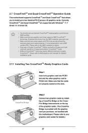
2.7 CrossFireXTM and Quad CrossFireXTM Operation Guide This motherboard supports CrossFireXTM and Quad CrossFireXTM that your graphics card driver supports AMD CrossFireXTM technology. Please refer to your system requires. Please refer to AMD... CrossFire Bridge is recommended to PCIE3 slot. Make sure that allows you to install up to enable CrossFireXTM. Make sure that are supported with this motherboard. Currently CrossFireXTM and Quad CrossFireXTM are AMD certified. 2. You should only use a AMD certified PSU. If you purchase, not bundled with Windows® 7 / 7 64...
2.7 CrossFireXTM and Quad CrossFireXTM Operation Guide This motherboard supports CrossFireXTM and Quad CrossFireXTM that your graphics card driver supports AMD CrossFireXTM technology. Please refer to your system requires. Please refer to AMD... CrossFire Bridge is recommended to PCIE3 slot. Make sure that allows you to install up to enable CrossFireXTM. Make sure that are supported with this motherboard. Currently CrossFireXTM and Quad CrossFireXTM are AMD certified. 2. You should only use a AMD certified PSU. If you purchase, not bundled with Windows® 7 / 7 64...
User Manual
Page 34
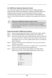
... from our support CD to our website for further information. An AMD Dual Graphics system includes an AMD Radeon HD 8000/7000 graphics processor and a motherboard based on [Auto]. Step 4. Please keep the default UEFI setting of AMD Dual Graphics Step 1. Boot into OS. Install the onboard VGA driver from onboard... a discrete graphics processor to the onboard VGA port. Connect the monitor cable to operate simultaneously with Windows® 8 / 7 OS. 2.8 AMD Dual Graphics Operation Guide This motherboard supports AMD Dual Graphics feature. Right-click the desktop.
... from our support CD to our website for further information. An AMD Dual Graphics system includes an AMD Radeon HD 8000/7000 graphics processor and a motherboard based on [Auto]. Step 4. Please keep the default UEFI setting of AMD Dual Graphics Step 1. Boot into OS. Install the onboard VGA driver from onboard... a discrete graphics processor to the onboard VGA port. Connect the monitor cable to operate simultaneously with Windows® 8 / 7 OS. 2.8 AMD Dual Graphics Operation Guide This motherboard supports AMD Dual Graphics feature. Right-click the desktop.
User Manual
Page 36
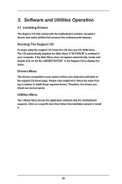
Software and Utilities Operation 3.1 Installing Drivers The Support CD that comes with the motherboard contains necessary drivers and useful utilities that the motherboard supports. Drivers Menu The drivers compatible to display the menu. Click on the file "ASRSETUP.EXE" in your computer. 3. Utilities... Menu The Utilities Menu shows the application software that enhance the motherboard's features. Running The Support CD To begin using the support CD, insert the CD into your system will be auto-detected and listed ...
Software and Utilities Operation 3.1 Installing Drivers The Support CD that comes with the motherboard contains necessary drivers and useful utilities that the motherboard supports. Drivers Menu The drivers compatible to display the menu. Click on the file "ASRSETUP.EXE" in your computer. 3. Utilities... Menu The Utilities Menu shows the application software that enhance the motherboard's features. Running The Support CD To begin using the support CD, insert the CD into your system will be auto-detected and listed ...

User Manual
Page 39
Enable this function and configure the period of time until the computer powers on, and the duration of the dehumidifying process. System Info View information about the system. 35 The fans will automatically shift to dampness. Dehumidifier Prevent motherboard damages due to the next speed level when the assigned temperature is met. FAN-Tastic Tuning Configure up to five different fan speeds using the graph. OC Tweaker Configurations for overclocking the system.
Enable this function and configure the period of time until the computer powers on, and the duration of the dehumidifying process. System Info View information about the system. 35 The fans will automatically shift to dampness. Dehumidifier Prevent motherboard damages due to the next speed level when the assigned temperature is met. FAN-Tastic Tuning Configure up to five different fan speeds using the graph. OC Tweaker Configurations for overclocking the system.

User Manual
Page 51
...only will continue with its test routines. You may also restart by pressing the reset button on . UEFI SETUP UTILITY 4.1 Introduction ASRock Interactive UEFI is constantly being updated, the following selections: Main For setting system time/date information OC Tweaker For overclocking configurations Advanced... Exit Exit the current screen or the UEFI SETUP UTILITY Use < > key or < > key to choose among the selections on the motherboard stores the UEFI SETUP UTILITY. You may not exactly match what you start up or down to select items, then press to configure your ...
...only will continue with its test routines. You may also restart by pressing the reset button on . UEFI SETUP UTILITY 4.1 Introduction ASRock Interactive UEFI is constantly being updated, the following selections: Main For setting system time/date information OC Tweaker For overclocking configurations Advanced... Exit Exit the current screen or the UEFI SETUP UTILITY Use < > key or < > key to choose among the selections on the motherboard stores the UEFI SETUP UTILITY. You may not exactly match what you start up or down to select items, then press to configure your ...

User Manual
Page 53
... and expense. AMD Application power Management Application Power Management (APM) ensures that average power consumption over a thermally significant time period remains at your components and motherboard. Please note that overclocking may cause damage to adjust EZ overclocking setting. If [Enabled] is selected, the power consumption is reduced when overclocking. 49 Spread...
... and expense. AMD Application power Management Application Power Management (APM) ensures that average power consumption over a thermally significant time period remains at your components and motherboard. Please note that overclocking may cause damage to adjust EZ overclocking setting. If [Enabled] is selected, the power consumption is reduced when overclocking. 49 Spread...

User Manual
Page 54
... stability. GFX Engine Clock Use this to adjust the value of this item. CPU Frequency Multiplier For safety and system stability, it is selected, the motherboard will display Processor Maximum Voltage for reference. Processor Maximum Voltage It will detect the memory module(s) inserted and assigns appropriate frequency automatically. 50 Multiplier/Voltage...
... stability. GFX Engine Clock Use this to adjust the value of this item. CPU Frequency Multiplier For safety and system stability, it is selected, the motherboard will display Processor Maximum Voltage for reference. Processor Maximum Voltage It will detect the memory module(s) inserted and assigns appropriate frequency automatically. 50 Multiplier/Voltage...

