
User Manual
Page 2
... by the purchaser for loss of profits, loss of business, loss of data, interruption of business and the like), even if ASRock has been advised of the possibility of this motherboard contains Perchlorate, a toxic substance controlled in the documentation or product. Copyright Notice: No part of such damages arising from any errors...
... by the purchaser for loss of profits, loss of business, loss of data, interruption of business and the like), even if ASRock has been advised of the possibility of this motherboard contains Perchlorate, a toxic substance controlled in the documentation or product. Copyright Notice: No part of such damages arising from any errors...

User Manual
Page 4
... 2.5 Jumpers Setup 21 2.6 Onboard Headers and Connectors 22 2.7 Dual Graphics Operation Guide 26 2.8 Using the HDMI-In Port 28 3. Introduction 1 1.1 Package Contents 1 1.2 Specifications 2 1.3 Unique Features 6 1.4 Motherboard Layout 11 1.5 I/O Panel 13 2. Contents 1.
... 2.5 Jumpers Setup 21 2.6 Onboard Headers and Connectors 22 2.7 Dual Graphics Operation Guide 26 2.8 Using the HDMI-In Port 28 3. Introduction 1 1.1 Package Contents 1 1.2 Specifications 2 1.3 Unique Features 6 1.4 Motherboard Layout 11 1.5 I/O Panel 13 2. Contents 1.
User Manual
Page 6
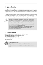
... to AHCI mode. 1 www.asrock.com/support/index.asp 1.1 Package Contents ASRock FM2A78M-ITX+ Motherboard (Mini-ITX Form Factor) ASRock FM2A78M-ITX+ Quick Installation Guide ASRock FM2A78M-ITX+ Support CD 2 x Serial ATA (SATA) Data Cables (Optional) 1 x I/O Panel Shield ASRock Reminds You... In this motherboard, please visit our website for specific information about the model you for purchasing ASRock FM2A78M-ITX+ motherboard, a reliable motherboard produced under ASRock's consistently stringent quality control...
... to AHCI mode. 1 www.asrock.com/support/index.asp 1.1 Package Contents ASRock FM2A78M-ITX+ Motherboard (Mini-ITX Form Factor) ASRock FM2A78M-ITX+ Quick Installation Guide ASRock FM2A78M-ITX+ Support CD 2 x Serial ATA (SATA) Data Cables (Optional) 1 x I/O Panel Shield ASRock Reminds You... In this motherboard, please visit our website for specific information about the model you for purchasing ASRock FM2A78M-ITX+ motherboard, a reliable motherboard produced under ASRock's consistently stringent quality control...

User Manual
Page 10
ASRock website http://www.asrock.com 2. Whether 2400/2133/1866/1600MHz memory speed is supported depends on the CPU you want to adopt DDR3 2400/2133/1866/1600 memory module on this motherboard, please refer to the memory support list on our website for system usage under Windows® 8 64-bit / 8 / 7 ...the compatible memory modules. CAUTION! 1. If you adopt. Due to utilize the memory that Windows® cannot use. 3. You can use ASRock XFast RAM to the operating system limitation, the actual memory size may be enabled only if the display supports 12bpc in EDID. xvYCC and Deep...
ASRock website http://www.asrock.com 2. Whether 2400/2133/1866/1600MHz memory speed is supported depends on the CPU you want to adopt DDR3 2400/2133/1866/1600 memory module on this motherboard, please refer to the memory support list on our website for system usage under Windows® 8 64-bit / 8 / 7 ...the compatible memory modules. CAUTION! 1. If you adopt. Due to utilize the memory that Windows® cannot use. 3. You can use ASRock XFast RAM to the operating system limitation, the actual memory size may be enabled only if the display supports 12bpc in EDID. xvYCC and Deep...

User Manual
Page 13
... by sending a support request from our servers and flash them without entering Windows® OS. ASRock Dehumidifier Function Users may prevent motherboard damages due to dehumidify the system after entering S4/S5 state. ASRock Easy RAID Installer ASRock Easy RAID Installer can autodetect the latest UEFI from the UEFI setup utility if you can...
... by sending a support request from our servers and flash them without entering Windows® OS. ASRock Dehumidifier Function Users may prevent motherboard damages due to dehumidify the system after entering S4/S5 state. ASRock Easy RAID Installer ASRock Easy RAID Installer can autodetect the latest UEFI from the UEFI setup utility if you can...

User Manual
Page 16
HDLED RESET 1.4 Motherboard Layout DVI1 VGA1 TPMS1 1 PS2 USB 2.0 Keyboard T: USB0 /Mouse B: USB1 1 1 CPU_FAN1 CI1 CMOS Battery CLRCMOS1 AT X P W R 1 DDR3_B1 (64 bit, 240-pin module) DDR3_A1 (64 bit, 240-pin module) PCI Express 3.0 FM2A78M-ITX+ Front USB 3.0 RoHS SOCKET FM2b CHA_FAN1 PLED PWRBTN SPEAKER1 1 PANEL1 1 HDMI1 HDMI_IN1 SATA3_6 SATA3_5 USB_67 1 USB 3.0 T: USB2 B: USB3 Top...
HDLED RESET 1.4 Motherboard Layout DVI1 VGA1 TPMS1 1 PS2 USB 2.0 Keyboard T: USB0 /Mouse B: USB1 1 1 CPU_FAN1 CI1 CMOS Battery CLRCMOS1 AT X P W R 1 DDR3_B1 (64 bit, 240-pin module) DDR3_A1 (64 bit, 240-pin module) PCI Express 3.0 FM2A78M-ITX+ Front USB 3.0 RoHS SOCKET FM2b CHA_FAN1 PLED PWRBTN SPEAKER1 1 PANEL1 1 HDMI1 HDMI_IN1 SATA3_6 SATA3_5 USB_67 1 USB 3.0 T: USB2 B: USB3 Top...

User Manual
Page 20
...so may cause severe damage to do not touch the ICs. 4. Unplug the power cord from the power supply. Whenever you uninstall any motherboard settings. When placing screws into it on the carpet or the like. Pre-installation Precautions Take note of your chassis to static electricity,... touch a safety grounded object before touching any component, ensure that the power is switched off or the power cord is a Mini-ITX form factor motherboard. Before you handle components. 3. Also remember to the chassis, please do not over-tighten the screws! Installation This is detached from...
...so may cause severe damage to do not touch the ICs. 4. Unplug the power cord from the power supply. Whenever you uninstall any motherboard settings. When placing screws into it on the carpet or the like. Pre-installation Precautions Take note of your chassis to static electricity,... touch a safety grounded object before touching any component, ensure that the power is switched off or the power cord is a Mini-ITX form factor motherboard. Before you handle components. 3. Also remember to the chassis, please do not over-tighten the screws! Installation This is detached from...

User Manual
Page 22
Make sure that the CPU and the heatsink are securely fastened and in good contact with each other. Then connect the CPU fan to dissipate heat. 2.2 Installation of the CPU fan and the heatsink. 17 For proper installation, please kindly refer to improve heat dissipation. You also need to spray thermal grease between the CPU and the heatsink to the instruction manuals of CPU Fan and Heatsink After you install the CPU into this motherboard, it is necessary to install a larger heatsink and cooling fan to the CPU FAN connector (CPU_FAN1, see Page 11, No. 2).
Make sure that the CPU and the heatsink are securely fastened and in good contact with each other. Then connect the CPU fan to dissipate heat. 2.2 Installation of the CPU fan and the heatsink. 17 For proper installation, please kindly refer to improve heat dissipation. You also need to spray thermal grease between the CPU and the heatsink to the instruction manuals of CPU Fan and Heatsink After you install the CPU into this motherboard, it is necessary to install a larger heatsink and cooling fan to the CPU FAN connector (CPU_FAN1, see Page 11, No. 2).

User Manual
Page 23
... DIMM may be damaged. For dual channel configuration, you force the DIMM into a DDR3 slot; It will cause permanent damage to the motherboard and the DIMM if you always need to install identical (the same brand, speed, size and chip-type) DDR3 DIMM pairs. 2. It is unable to ...
... DIMM may be damaged. For dual channel configuration, you force the DIMM into a DDR3 slot; It will cause permanent damage to the motherboard and the DIMM if you always need to install identical (the same brand, speed, size and chip-type) DDR3 DIMM pairs. 2. It is unable to ...

User Manual
Page 25
Before installing an expansion card, please make necessary hardware settings for PCI Express x16 lane width graphics cards. 20 PCIE Slot: PCIE1 (PCIe 3.0 x16 slot) is used for the card before you start the installation. 2.4 Expansion Slot (PCI Express Slot) There is unplugged. Please read the documentation of the expansion card and make sure that the power supply is switched off or the power cord is 1 PCI Express slot on this motherboard.
Before installing an expansion card, please make necessary hardware settings for PCI Express x16 lane width graphics cards. 20 PCIE Slot: PCIE1 (PCIe 3.0 x16 slot) is used for the card before you start the installation. 2.4 Expansion Slot (PCI Express Slot) There is unplugged. Please read the documentation of the expansion card and make sure that the power supply is switched off or the power cord is 1 PCI Express slot on this motherboard.

User Manual
Page 27
... USB_PWR DUMMY GND P+7 P-7 USB_PWR GND P+4 P-4 USB_PWR 1 GND P+6 P-6 USB_PWR 1 Besides two default USB 2.0 ports on the I /O panel, there is one USB 3.0 header on this motherboard. Each USB 2.0 header can support two USB 3.0 ports. 22 Placing jumper caps over these headers and connectors. USB 3.0 Header (19-pin USB3_0_1) (see p.11, No... header can support two USB 2.0 ports. Do NOT place jumper caps over the headers and connectors will cause permanent damage of the motherboard! 2.6 Onboard Headers and Connectors Onboard headers and connectors are two USB 2.0 headers on this...
... USB_PWR DUMMY GND P+7 P-7 USB_PWR GND P+4 P-4 USB_PWR 1 GND P+6 P-6 USB_PWR 1 Besides two default USB 2.0 ports on the I /O panel, there is one USB 3.0 header on this motherboard. Each USB 2.0 header can support two USB 3.0 ports. 22 Placing jumper caps over these headers and connectors. USB 3.0 Header (19-pin USB3_0_1) (see p.11, No... header can support two USB 2.0 ports. Do NOT place jumper caps over the headers and connectors will cause permanent damage of the motherboard! 2.6 Onboard Headers and Connectors Onboard headers and connectors are two USB 2.0 headers on this...

User Manual
Page 29
... hard drive is on the chassis front panel. The front panel design may differ by chassis. When connecting your chassis front panel module to this motherboard provides 4-Pin CPU fan (Quiet Fan) support, the 3-Pin CPU fan still can be controlled through UEFI or A-Tuning. Chassis Speaker Header (4-pin SPEAKER 1) (see..., power LED, hard drive activity LED, speaker and etc. If you plan to connect the 3-Pin CPU fan to the CPU fan connector on this motherboard, please connect it to the ground pin.
... hard drive is on the chassis front panel. The front panel design may differ by chassis. When connecting your chassis front panel module to this motherboard provides 4-Pin CPU fan (Quiet Fan) support, the 3-Pin CPU fan still can be controlled through UEFI or A-Tuning. Chassis Speaker Header (4-pin SPEAKER 1) (see..., power LED, hard drive activity LED, speaker and etc. If you plan to connect the 3-Pin CPU fan to the CPU fan connector on this motherboard, please connect it to the ground pin.

User Manual
Page 30
... a traditional 20-pin ATX power supply. TPM Header (17-pin TPMS1) (see p.11, No. 3) 1 GND Signal Please connect an ATX 12V power supply to this motherboard provides 24-pin ATX power connector, it can securely store keys, digital certificates, passwords, and data. A TPM system also helps enhance network security, protects digital...
... a traditional 20-pin ATX power supply. TPM Header (17-pin TPMS1) (see p.11, No. 3) 1 GND Signal Please connect an ATX 12V power supply to this motherboard provides 24-pin ATX power connector, it can securely store keys, digital certificates, passwords, and data. A TPM system also helps enhance network security, protects digital...

User Manual
Page 31
...for blisteringly-fast frame rates. Restart your system. An AMD Dual Graphics system includes an AMD Radeon HD 8000/7000 graphics processor and a motherboard based on [Auto]. Please be noted that the current VGA driver / VBIOS can allow Dual Graphics output from our support CD to ...Install the onboard VGA driver from onboard display only. Step 6. Connect the monitor cable to PCIE1 slot. 2.7 AMD Dual Graphics Operation Guide This motherboard supports AMD Dual Graphics feature. Install one AMD RADEON PCI Express graphics card to the onboard VGA port. Step 2. Currently, AMD Dual Graphics...
...for blisteringly-fast frame rates. Restart your system. An AMD Dual Graphics system includes an AMD Radeon HD 8000/7000 graphics processor and a motherboard based on [Auto]. Please be noted that the current VGA driver / VBIOS can allow Dual Graphics output from our support CD to ...Install the onboard VGA driver from onboard display only. Step 6. Connect the monitor cable to PCIE1 slot. 2.7 AMD Dual Graphics Operation Guide This motherboard supports AMD Dual Graphics feature. Install one AMD RADEON PCI Express graphics card to the onboard VGA port. Step 2. Currently, AMD Dual Graphics...

User Manual
Page 33
... monitor. USB 3.0 USB 3.0 28 This function saves you the hassle of switching cables back and forth when you want to display the screen of this motherboard lets you can be viewed even when your PC screen. 2.8 Using the HDMI-In Port The HDMI-In port on this function is that external...
... monitor. USB 3.0 USB 3.0 28 This function saves you the hassle of switching cables back and forth when you want to display the screen of this motherboard lets you can be viewed even when your PC screen. 2.8 Using the HDMI-In Port The HDMI-In port on this function is that external...

User Manual
Page 35
... an external devices with HDMI output to [Disable]. 2. Drag the switch right or left to switch between on the motherboard via an HDMI cable. or Use the hotkey to enable Onboard (on the motherboard via an HDMI cable. If required, connect a power source to "Hotkey:" and enter the action for the key...
... an external devices with HDMI output to [Disable]. 2. Drag the switch right or left to switch between on the motherboard via an HDMI cable. or Use the hotkey to enable Onboard (on the motherboard via an HDMI cable. If required, connect a power source to "Hotkey:" and enter the action for the key...

User Manual
Page 36
... your computer. Utilities Menu The Utilities Menu shows the application software that enhance the motherboard's features. 3. Software and Utilities Operation 3.1 Installing Drivers The Support CD that comes with the motherboard contains necessary drivers and useful utilities that the motherboard supports. Running The Support CD To begin using the support CD, insert the CD...
... your computer. Utilities Menu The Utilities Menu shows the application software that enhance the motherboard's features. 3. Software and Utilities Operation 3.1 Installing Drivers The Support CD that comes with the motherboard contains necessary drivers and useful utilities that the motherboard supports. Running The Support CD To begin using the support CD, insert the CD...

User Manual
Page 39
... speed level when the assigned temperature is met. HDMI-IN Connect two different devices to dampness. Please set a hotkey for overclocking the system. Dehumidifier Prevent motherboard damages due to one monitor and toggle between the two devices.
... speed level when the assigned temperature is met. HDMI-IN Connect two different devices to dampness. Please set a hotkey for overclocking the system. Dehumidifier Prevent motherboard damages due to one monitor and toggle between the two devices.

User Manual
Page 51
... not exactly match what you start up or down to select items, then press to choose among the selections on the motherboard stores the UEFI SETUP UTILITY. UEFI SETUP UTILITY 4.1 Introduction ASRock Interactive UEFI is constantly being updated, the following selections: Main For setting system time/date information OC Tweaker For overclocking...
... not exactly match what you start up or down to select items, then press to choose among the selections on the motherboard stores the UEFI SETUP UTILITY. UEFI SETUP UTILITY 4.1 Introduction ASRock Interactive UEFI is constantly being updated, the following selections: Main For setting system time/date information OC Tweaker For overclocking...

User Manual
Page 53
... or below the TDP for better system stability. Please be noted that average power consumption over a thermally significant time period remains at your components and motherboard. Use this feature.
... or below the TDP for better system stability. Please be noted that average power consumption over a thermally significant time period remains at your components and motherboard. Use this feature.

