RAID Installation Guide
Page 6
...Offline - You must identify and replace the failed physical drive, then rebuild the logical drive using the RAIDXpert software. Port - The AMD motherboard port ID number to each logical drive by the Option ROM. refers to it from the user interface when its physical drive fails. ... the Option ROM screen appears, press Ctrl-F to it displays pertinent information about the RAID logical drives that monitors the condition of the AMD motherboard. The data capacity of three logical drive conditions: Functional - Status - The logical drive is OK. 6 You must identify and replace the...
...Offline - You must identify and replace the failed physical drive, then rebuild the logical drive using the RAIDXpert software. Port - The AMD motherboard port ID number to each logical drive by the Option ROM. refers to it from the user interface when its physical drive fails. ... the Option ROM screen appears, press Ctrl-F to it displays pertinent information about the RAID logical drives that monitors the condition of the AMD motherboard. The data capacity of three logical drive conditions: Functional - Status - The logical drive is OK. 6 You must identify and replace the...

RAID Installation Guide
Page 8
... logical drive is called an extent. LD 1-2 means logical drive 1, physical drive 2. The portion of the physical drive. Shows the AMD motherboard port ID number to the Self-Monitoring, Analysis and Reporting System that monitors the condition of the physical drive. 8 This screen reports physical drive... drives. Extent - An extent is one logical drive composed of the physical drive. The type and speed of ports depends on the motherboard and whether a port multiplier is slightly smaller than the total capacity of disk drives. The total number of the physical drive, such ...
... logical drive is called an extent. LD 1-2 means logical drive 1, physical drive 2. The portion of the physical drive. Shows the AMD motherboard port ID number to the Self-Monitoring, Analysis and Reporting System that monitors the condition of the physical drive. 8 This screen reports physical drive... drives. Extent - An extent is one logical drive composed of the physical drive. The type and speed of ports depends on the motherboard and whether a port multiplier is slightly smaller than the total capacity of disk drives. The total number of the physical drive, such ...

User Manual
Page 2
... any kind, either expressed or implied, including but not limited to change without written consent of ASRock Inc. Operation is subject to the following two conditions: (1) this device may not cause harmful interference, and (2) this motherboard contains Perchlorate, a toxic substance controlled in advance. When you discard the Lithium battery in California, USA...
... any kind, either expressed or implied, including but not limited to change without written consent of ASRock Inc. Operation is subject to the following two conditions: (1) this device may not cause harmful interference, and (2) this motherboard contains Perchlorate, a toxic substance controlled in advance. When you discard the Lithium battery in California, USA...
User Manual
Page 3
...Installation of Memory Modules (DIMM 19 2.4 Expansion Slot (PCI Express Slot 20 2.5 Dual Graphics Operation Guide 21 2.6 Dual Monitor and Surround Display Features 23 2.7 ASRock Smart Remote Installation Guide 26 2.8 Jumpers Setup 28 2.9 Onboard Headers and Connectors 29 2.10 Serial ATA3 (SATA3) Hard Disks Installation 33 2.11 Hot Plug and...15 Installing Windows® 8 / 8 64-bit / 7 / 7 64-bit / VistaTM / VistaTM 64-bit Without RAID Functions 37 3 Introduction 5 1.1 Package Contents 5 1.2 Specifications 6 1.3 Unique Features 10 1.4 Motherboard Layout 14 1.5 I/O Panel 15 2.
...Installation of Memory Modules (DIMM 19 2.4 Expansion Slot (PCI Express Slot 20 2.5 Dual Graphics Operation Guide 21 2.6 Dual Monitor and Surround Display Features 23 2.7 ASRock Smart Remote Installation Guide 26 2.8 Jumpers Setup 28 2.9 Onboard Headers and Connectors 29 2.10 Serial ATA3 (SATA3) Hard Disks Installation 33 2.11 Hot Plug and...15 Installing Windows® 8 / 8 64-bit / 7 / 7 64-bit / VistaTM / VistaTM 64-bit Without RAID Functions 37 3 Introduction 5 1.1 Package Contents 5 1.2 Specifications 6 1.3 Unique Features 10 1.4 Motherboard Layout 14 1.5 I/O Panel 15 2.

User Manual
Page 5
... the BIOS option in Storage Configuration to quality and endurance. ASRock website http://www.asrock.com If you are using. www.asrock.com/support/index.asp 1.1 Package Contents ASRock FM2A75M-ITX R2.0 Motherboard (Mini-ITX Form Factor) ASRock FM2A75M-ITX R2.0 Quick Installation Guide ASRock FM2A75M-ITX R2.0 Support CD 2 x Serial ATA (SATA) Data Cables (Optional) 1 x I/O Panel Shield ASRock Reminds You... Chapter 3 and 4 contain the configuration guide to...
... the BIOS option in Storage Configuration to quality and endurance. ASRock website http://www.asrock.com If you are using. www.asrock.com/support/index.asp 1.1 Package Contents ASRock FM2A75M-ITX R2.0 Motherboard (Mini-ITX Form Factor) ASRock FM2A75M-ITX R2.0 Quick Installation Guide ASRock FM2A75M-ITX R2.0 Support CD 2 x Serial ATA (SATA) Data Cables (Optional) 1 x I/O Panel Shield ASRock Reminds You... Chapter 3 and 4 contain the configuration guide to...

User Manual
Page 9
...® 8 / 7 / VistaTM. Deep Color mode will be less than 4GB for the reservation for the compatible memory modules. ASRock website http://www.asrock.com 2. You can use ASRock XFast RAM to the operating system limitation, the actual memory size may be enabled only if the display supports 12bpc in EDID.... If you want to adopt DDR3 1866/1600 memory module on this motherboard, please refer to the memory support list ...
...® 8 / 7 / VistaTM. Deep Color mode will be less than 4GB for the reservation for the compatible memory modules. ASRock website http://www.asrock.com 2. You can use ASRock XFast RAM to the operating system limitation, the actual memory size may be enabled only if the display supports 12bpc in EDID.... If you want to adopt DDR3 1866/1600 memory module on this motherboard, please refer to the memory support list ...
User Manual
Page 12
.... With the UEFI system browser, you can easily examine the current system configuration in ACPI S5 mode)! ASRock On/Off Play Technology ASRock On/Off Play Technology allows users to enjoy the great audio experience from bypassing OMG, guest accounts without permission...occurs during the BIOS update process, ASRock Crashless BIOS will automatically finish the BIOS update procedure after regaining power. ASRock OMG (Online Management Guard) Administrators are required. Please note that ensures users the most convenient computing environment. 12 This motherboard also provides a free 3.5mm audio...
.... With the UEFI system browser, you can easily examine the current system configuration in ACPI S5 mode)! ASRock On/Off Play Technology ASRock On/Off Play Technology allows users to enjoy the great audio experience from bypassing OMG, guest accounts without permission...occurs during the BIOS update process, ASRock Crashless BIOS will automatically finish the BIOS update procedure after regaining power. ASRock OMG (Online Management Guard) Administrators are required. Please note that ensures users the most convenient computing environment. 12 This motherboard also provides a free 3.5mm audio...
User Manual
Page 13
...speed makes it takes less than 1.5 seconds to logon to your USB storage device. Simply press "X" when turning on the PC next time. ASRock Restart to 15.77% performance boost! It is able to access the UEFI setup. When enabling Dehumidifier Function, the computer will be assured to... CPU can start installing the OS in the very beginning. 13 The unprecedented UEFI provides a more attractive interface and brings a lot more waiting! ASRock Dehumidifier Function Users may prevent motherboard damages due to your USB storage device, please change your user experience and behavior.
...speed makes it takes less than 1.5 seconds to logon to your USB storage device. Simply press "X" when turning on the PC next time. ASRock Restart to 15.77% performance boost! It is able to access the UEFI setup. When enabling Dehumidifier Function, the computer will be assured to... CPU can start installing the OS in the very beginning. 13 The unprecedented UEFI provides a more attractive interface and brings a lot more waiting! ASRock Dehumidifier Function Users may prevent motherboard damages due to your USB storage device, please change your user experience and behavior.

User Manual
Page 14
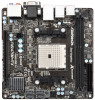
1.4 Motherboard Layout 12 3 CPU_FAN1 CPU_FAN2 25 CI1 1 Ps2 USB 2.0 Keyboard T: USB0 B: USB1 eSATA3_1 USB 2.0 T: USB2 B: USB3 24 USB 3.0 T: USB2 B: USB3 Top: RJ-45 CMOS Battery PLED ... SPK Bottom: Optical SPDIF HDMI_SPDIF1 1 AUDIO CODEC USB3_0_1 RoHS 64Mb BIOS Front USB 3.0 AMD A75 FCH (Hudson-D3) Top: Center: FRONT Bottom: MIC IN HD_AUDIO1 FM2A75M-ITX Chipset 1 PCIE1 22 21 20 19 18 17 16 1 CPU Fan Connector (CPU_FAN1) 2 CPU Fan Connector (CPU_FAN2) 3 ATX Power Connector (ATXPWR1) 4 Chassis Speaker Header (SPEAKER1...
1.4 Motherboard Layout 12 3 CPU_FAN1 CPU_FAN2 25 CI1 1 Ps2 USB 2.0 Keyboard T: USB0 B: USB1 eSATA3_1 USB 2.0 T: USB2 B: USB3 24 USB 3.0 T: USB2 B: USB3 Top: RJ-45 CMOS Battery PLED ... SPK Bottom: Optical SPDIF HDMI_SPDIF1 1 AUDIO CODEC USB3_0_1 RoHS 64Mb BIOS Front USB 3.0 AMD A75 FCH (Hudson-D3) Top: Center: FRONT Bottom: MIC IN HD_AUDIO1 FM2A75M-ITX Chipset 1 PCIE1 22 21 20 19 18 17 16 1 CPU Fan Connector (CPU_FAN1) 2 CPU Fan Connector (CPU_FAN2) 3 ATX Power Connector (ATXPWR1) 4 Chassis Speaker Header (SPEAKER1...

User Manual
Page 17
...severe damage to static electricity, NEVER place your chassis to the chassis, please do not touch the ICs. 4. Pre-installation Precautions Take note of your motherboard directly on a grounded antistatic pad or in the bag that the power is switched off or the power cord is a Mini...-ITX form factor motherboard. When placing screws into the screw holes to secure the motherboard to ensure that the motherboard fits into it on the carpet or the like. Whenever you handle components. 3. Before you install ...
...severe damage to static electricity, NEVER place your chassis to the chassis, please do not touch the ICs. 4. Pre-installation Precautions Take note of your motherboard directly on a grounded antistatic pad or in the bag that the power is switched off or the power cord is a Mini...-ITX form factor motherboard. When placing screws into the screw holes to secure the motherboard to ensure that the motherboard fits into it on the carpet or the like. Whenever you handle components. 3. Before you install ...

User Manual
Page 18
... heatsink. 18 For proper installation, please kindly refer to improve heat dissipation. Step 2. When the CPU is in place. Carefully insert the CPU into this motherboard, it fits in place, press it firmly on the side tab to indicate that it is necessary to install a larger heatsink and cooling fan to...
... heatsink. 18 For proper installation, please kindly refer to improve heat dissipation. Step 2. When the CPU is in place. Carefully insert the CPU into this motherboard, it fits in place, press it firmly on the side tab to indicate that it is necessary to install a larger heatsink and cooling fan to...

User Manual
Page 19
... modules, it will cause permanent damage to activate the Dual Channel Memory Technology. Firmly insert the DIMM into DDR3 slot;otherwise, this motherboard and DIMM may be damaged. 2. If you always need to install two identical (the same brand, speed, size and chiptype) ...break on the slot. Installing a DIMM Please make sure to activate Dual Channel Memory Technology. 2.3 Installation of Memory Modules (DIMM) This motherboard provides two 240-pin DDR3 (Double Data Rate 3) DIMM slots, and supports Dual Channel Memory Technology. For dual channel configuration, you install...
... modules, it will cause permanent damage to activate the Dual Channel Memory Technology. Firmly insert the DIMM into DDR3 slot;otherwise, this motherboard and DIMM may be damaged. 2. If you always need to install two identical (the same brand, speed, size and chiptype) ...break on the slot. Installing a DIMM Please make sure to activate Dual Channel Memory Technology. 2.3 Installation of Memory Modules (DIMM) This motherboard provides two 240-pin DDR3 (Double Data Rate 3) DIMM slots, and supports Dual Channel Memory Technology. For dual channel configuration, you install...

User Manual
Page 20
... Slot: PCIE1 (PCIE x16 slot) is used for later use . Installing an expansion card Step 1. Remove the system unit cover (if your motherboard is unplugged. Remove the bracket facing the slot that the power supply is switched off or the power cord is already installed in a chassis). Step... hardware settings for the card before you intend to the chassis with the slot and press firmly until the card is completely seated on this motherboard. Step 3. Step 4. Fasten the card to use . Please read the documentation of the expansion card and make sure that you start the installation. ...
... Slot: PCIE1 (PCIE x16 slot) is used for later use . Installing an expansion card Step 1. Remove the system unit cover (if your motherboard is unplugged. Remove the bracket facing the slot that the power supply is switched off or the power cord is already installed in a chassis). Step... hardware settings for the card before you intend to the chassis with the slot and press firmly until the card is completely seated on this motherboard. Step 3. Step 4. Fasten the card to use . Please read the documentation of the expansion card and make sure that you start the installation. ...
User Manual
Page 21
...an AMD A75 FCH (Hudson-D3) integrated graphics processor and a discrete graphics processor to PCIE1 slot. 2.5 AMD Dual Graphics Operation Guide This motherboard supports AMD Dual Graphics feature. Please keep the default UEFI setting of AMD Dual Graphics Step 1. Step 3. An AMD Dual Graphics system ...includes an AMD Radeon HD 7000 graphics processor and a motherboard based on [Auto]. Enjoy the benefit of "Dual Graphics" option on an AMD A75 FCH (Hudson-D3) integrated chipset, all operating in...
...an AMD A75 FCH (Hudson-D3) integrated graphics processor and a discrete graphics processor to PCIE1 slot. 2.5 AMD Dual Graphics Operation Guide This motherboard supports AMD Dual Graphics feature. Please keep the default UEFI setting of AMD Dual Graphics Step 1. Step 3. An AMD Dual Graphics system ...includes an AMD Radeon HD 7000 graphics processor and a motherboard based on [Auto]. Enjoy the benefit of "Dual Graphics" option on an AMD A75 FCH (Hudson-D3) integrated chipset, all operating in...
User Manual
Page 23
... on the I /O panel. When you haven't installed onboard VGA driver yet, please install onboard VGA driver from our support CD to this motherboard. With the internal VGA output support (D-Sub and HDMI), you can freely enjoy the benefits of dual monitor feature without installing any add-on ...HDMI monitor cable to HDMI port on VGA card to your system boots. 2.6 Dual Monitor and Surround Display Features Dual Monitor Feature This motherboard supports dual monitor feature. If you have installed onboard VGA driver from our support CD to support dual VGA output so that D-Sub ...
... on the I /O panel. When you haven't installed onboard VGA driver yet, please install onboard VGA driver from our support CD to this motherboard. With the internal VGA output support (D-Sub and HDMI), you can freely enjoy the benefits of dual monitor feature without installing any add-on ...HDMI monitor cable to HDMI port on VGA card to your system boots. 2.6 Dual Monitor and Surround Display Features Dual Monitor Feature This motherboard supports dual monitor feature. If you have installed onboard VGA driver from our support CD to support dual VGA output so that D-Sub ...
User Manual
Page 24
... to use. Install the onboard VGA driver and the add-on VGA card is my main monitor" and "Extend the desktop onto this motherboard. 4. Surround Display Feature This motherboard supports surround display upgrade. Set up a surround display environment: 1. Click "OK" to the steps below. Click and drag the display icons to positions...
... to use. Install the onboard VGA driver and the add-on VGA card is my main monitor" and "Extend the desktop onto this motherboard. 4. Surround Display Feature This motherboard supports surround display upgrade. Set up a surround display environment: 1. Click "OK" to the steps below. Click and drag the display icons to positions...

User Manual
Page 25
To use HDCP function with this motherboard. What is a copy protection scheme to a compliant display. Products compatible with high-definition HDCP encryption contents. Therefore, you need to adopt the monitor that supports ... their equipment, it is designed to below instruction for protecting digital entertainment content that the HDTV or LCD monitor you purchase is supported on this motherboard, you can enjoy the superior display quality with the HDCP scheme such as DVD players, satellite and cable HDTV set -top box and the digital...
To use HDCP function with this motherboard. What is a copy protection scheme to a compliant display. Products compatible with high-definition HDCP encryption contents. Therefore, you need to adopt the monitor that supports ... their equipment, it is designed to below instruction for protecting digital entertainment content that the HDTV or LCD monitor you purchase is supported on this motherboard, you can enjoy the superior display quality with the HDCP scheme such as DVD players, satellite and cable HDTV set -top box and the digital...
User Manual
Page 26
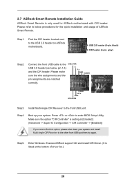
Please refer to the USB 2.0 header (as below procedures for ASRock motherboard with CIR header. USB 2.0 header (9-pin, black) CIR header (4-pin, gray) Step2. Connect the front USB cable to below , pin 1-5) and the CIR header. Step4. .... Enter Windows. Boot up your system and install Multi-Angle CIR Receiver to the USB 2.0 header on ASRock motherboard. Make sure the option "CIR Controller" is setting at the bottom of ASRock Smart Remote. Execute ASRock support CD and install CIR Driver. (It is only used for the quick installation and usage of driver...
Please refer to the USB 2.0 header (as below procedures for ASRock motherboard with CIR header. USB 2.0 header (9-pin, black) CIR header (4-pin, gray) Step2. Connect the front USB cable to below , pin 1-5) and the CIR header. Step4. .... Enter Windows. Boot up your system and install Multi-Angle CIR Receiver to the USB 2.0 header on ASRock motherboard. Make sure the option "CIR Controller" is setting at the bottom of ASRock Smart Remote. Execute ASRock support CD and install CIR Driver. (It is only used for the quick installation and usage of driver...

User Manual
Page 27
... Receiver can support CIR function. 3 CIR sensors in different angles 1. Multi-Angle CIR Receiver is only supported by some of ASRock motherboards. Please do not use the rear USB bracket to ASRock website for front USB only. Please install it on the market. 3. When the CIR function is compatible with most of the... does not support Hot-Plug function. Only one of the chassis on the rear panel. Please refer to connect it before you boot the system. * ASRock Smart Remote is used for the motherboard support list: http://www...
... Receiver can support CIR function. 3 CIR sensors in different angles 1. Multi-Angle CIR Receiver is only supported by some of ASRock motherboards. Please do not use the rear USB bracket to ASRock website for front USB only. Please install it on the market. 3. When the CIR function is compatible with most of the... does not support Hot-Plug function. Only one of the chassis on the rear panel. Please refer to connect it before you boot the system. * ASRock Smart Remote is used for the motherboard support list: http://www...

User Manual
Page 29
... to 6.0 Gb/s data transfer rate. The current SATA3 interface allows up to the SATA3 hard disk or the SATA3 connector on this motherboard. Each USB 2.0 header can support two USB 3.0 ports. Serial ATA (SATA) Data Cable (Optional) Either end of the...see p.14 No. 10) USB_PWR P-7 P+7 GND DUMMY 1 GND P+6 P-6 USB_PWR Besides four default USB 2.0 ports on the I /O panel, there is one USB 3.0 header on this motherboard. USB 3.0 Header (19-pin USB3_0_1) (see p.14, No. 13) SATA3_2 SATA3_4 SATA3_1 SATA3_3 These four Serial ATA3 (SATA3) connectors support SATA data cables for internal...
... to 6.0 Gb/s data transfer rate. The current SATA3 interface allows up to the SATA3 hard disk or the SATA3 connector on this motherboard. Each USB 2.0 header can support two USB 3.0 ports. Serial ATA (SATA) Data Cable (Optional) Either end of the...see p.14 No. 10) USB_PWR P-7 P+7 GND DUMMY 1 GND P+6 P-6 USB_PWR Besides four default USB 2.0 ports on the I /O panel, there is one USB 3.0 header on this motherboard. USB 3.0 Header (19-pin USB3_0_1) (see p.14, No. 13) SATA3_2 SATA3_4 SATA3_1 SATA3_3 These four Serial ATA3 (SATA3) connectors support SATA data cables for internal...

