
User Manual
Page 5
www.asrock.com/support/index.asp 1.1 Package Contents ASRock FM2A68M-HD+ Motherboard (Micro ATX Form Factor) ASRock FM2A68M-HD+ Quick Installation Guide ASRock FM2A68M-HD+ Support CD 2 x Serial ATA (SATA) Data Cables (Optional) 1 x I/O Panel Shield 1 English Because the motherboard speciications and the BIOS software might be updated, the content of the BIOS setup. Chapter 4 contains the coniguration guide of this manual will...
www.asrock.com/support/index.asp 1.1 Package Contents ASRock FM2A68M-HD+ Motherboard (Micro ATX Form Factor) ASRock FM2A68M-HD+ Quick Installation Guide ASRock FM2A68M-HD+ Support CD 2 x Serial ATA (SATA) Data Cables (Optional) 1 x I/O Panel Shield 1 English Because the motherboard speciications and the BIOS software might be updated, the content of the BIOS setup. Chapter 4 contains the coniguration guide of this manual will...

User Manual
Page 15
For proper installation, please kindly refer to the instruction manuals of CPU Fan and Heatsink After you install the CPU into this motherboard, it is necessary to install a larger heatsink and cooling fan to dissipate heat. Make sure that the CPU and the heatsink are securely fastened and in good contact with each other. Then connect the CPU fan to improve heat dissipation. FM2A68M-HD+ 2.2 Installation of the CPU fan and the heatsink. 11 English You also need to spray thermal grease between the CPU and the heatsink to the CPU FAN connector (CPU_FAN1, see Page 6, No. 2).
For proper installation, please kindly refer to the instruction manuals of CPU Fan and Heatsink After you install the CPU into this motherboard, it is necessary to install a larger heatsink and cooling fan to dissipate heat. Make sure that the CPU and the heatsink are securely fastened and in good contact with each other. Then connect the CPU fan to improve heat dissipation. FM2A68M-HD+ 2.2 Installation of the CPU fan and the heatsink. 11 English You also need to spray thermal grease between the CPU and the heatsink to the CPU FAN connector (CPU_FAN1, see Page 6, No. 2).

User Manual
Page 20
... 1 GND P+ PUSB_PWR Besides four default USB 2.0 ports on the I /O panel, there is an interface for internal storage devices. Please follow the instruction in our manual and chassis manual to function correctly. Placing jumper caps over these headers and connectors. Each USB 2.0 header can support two USB 3.0 ports. 2.6 Onboard Headers and Connectors Onboard...
... 1 GND P+ PUSB_PWR Besides four default USB 2.0 ports on the I /O panel, there is an interface for internal storage devices. Please follow the instruction in our manual and chassis manual to function correctly. Placing jumper caps over these headers and connectors. Each USB 2.0 header can support two USB 3.0 ports. 2.6 Onboard Headers and Connectors Onboard...

User Manual
Page 44
Configuration options: [Auto] and [Manual]. The default value is reduced when overclocking. 40 English AMD Turbo Core Technology This item appears only when the processor you can set up overclocking ...
Configuration options: [Auto] and [Manual]. The default value is reduced when overclocking. 40 English AMD Turbo Core Technology This item appears only when the processor you can set up overclocking ...

User Manual
Page 45
If it is recommended to [Manual], you may adjust the value of Processor Frequency and Processor Voltage. GFX Engine Clock Use this to [Auto] by default. Multiplier/Voltage Change This item ... adjust GFX Engine Clock. DRAM Timing Coniguration DRAM Frequency If [Auto] is [Auto]. However, it is set to keep the default value for system stability. FM2A68M-HD+ Processor Maximum Frequency It will display Processor Maximum Frequency for reference. The default value is selected, the motherboard will display Processor Maximum Voltage for reference...
If it is recommended to [Manual], you may adjust the value of Processor Frequency and Processor Voltage. GFX Engine Clock Use this to [Auto] by default. Multiplier/Voltage Change This item ... adjust GFX Engine Clock. DRAM Timing Coniguration DRAM Frequency If [Auto] is [Auto]. However, it is set to keep the default value for system stability. FM2A68M-HD+ Processor Maximum Frequency It will display Processor Maximum Frequency for reference. The default value is selected, the motherboard will display Processor Maximum Voltage for reference...

User Manual
Page 60
... enable or disable case open has been detected. CPU Fan 1 Setting This allows you to set the CPU fan 1 speed. Coni guration options: [Full On], [Manual Mode] and [Automatic Mode]. Case Open Feature This allows you to set the chassis fan 1 speed. Chassis Fan 1 Setting This allows you to monitor the...
... enable or disable case open has been detected. CPU Fan 1 Setting This allows you to set the CPU fan 1 speed. Coni guration options: [Full On], [Manual Mode] and [Automatic Mode]. Case Open Feature This allows you to set the chassis fan 1 speed. Chassis Fan 1 Setting This allows you to monitor the...
Quick Installation Guide
Page 7
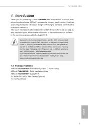
... modiications of this manual will be updated, the content of this motherboard, please visit our website for speciic information about the model you for purchasing ASRock FM2A68M-HD+ motherboard, a reliable motherboard produced under ASRock's consistently stringent quality control. www.asrock.com/support/index.asp 1.1 Package Contents ASRock FM2A68M-HD+ Motherboard (Micro ATX Form Factor) ASRock FM2A68M-HD+ Quick Installation Guide ASRock FM2A68M-HD+ Support CD...
... modiications of this manual will be updated, the content of this motherboard, please visit our website for speciic information about the model you for purchasing ASRock FM2A68M-HD+ motherboard, a reliable motherboard produced under ASRock's consistently stringent quality control. www.asrock.com/support/index.asp 1.1 Package Contents ASRock FM2A68M-HD+ Motherboard (Micro ATX Form Factor) ASRock FM2A68M-HD+ Quick Installation Guide ASRock FM2A68M-HD+ Support CD...

Quick Installation Guide
Page 13
...Besides four default USB 2.0 ports on the I /O panel, there is an interface for internal storage devices. Please follow the instruction in our manual and chassis manual to 6.0 Gb/s data transfer rate. USB 3.0 Header (19-pin USB_11_12) (see p.1, No. 8) SATA_1 SATA_2 SATA_3 SATA_4 These four Serial...3.0 ports. This USB 3.0 header can support two USB 2.0 ports. Placing jumper caps over these headers and connectors. FM2A68M-HD+ 1.4 Onboard Headers and Connectors Onboard headers and connectors are two USB 2.0 headers on the chassis must support HDA to function correctly.
...Besides four default USB 2.0 ports on the I /O panel, there is an interface for internal storage devices. Please follow the instruction in our manual and chassis manual to 6.0 Gb/s data transfer rate. USB 3.0 Header (19-pin USB_11_12) (see p.1, No. 8) SATA_1 SATA_2 SATA_3 SATA_4 These four Serial...3.0 ports. This USB 3.0 header can support two USB 2.0 ports. Placing jumper caps over these headers and connectors. FM2A68M-HD+ 1.4 Onboard Headers and Connectors Onboard headers and connectors are two USB 2.0 headers on the chassis must support HDA to function correctly.
RAID Installation Guide
Page 2
... drives of the same model and capacity when creating a RAID set the option to RAID The term "RAID" stands for "Redundant Array of the "User Manual" in parallel, interleaved stacks. Hot-Plug any fault tolerance. Although RAID 0 function can start to use the onboard RAID Option ROM Utility to configure RAID...
... drives of the same model and capacity when creating a RAID set the option to RAID The term "RAID" stands for "Redundant Array of the "User Manual" in parallel, interleaved stacks. Hot-Plug any fault tolerance. Although RAID 0 function can start to use the onboard RAID Option ROM Utility to configure RAID...

RAID Installation Guide
Page 14
... . 2. Press to the first logical drive. Use the full capacity of the disk drives for one of the following the detailed instruction of the "User Manual" in Disk Assignments as the above -mentioned procedures, press to restart your computer by following actions: 1. Split the disk drives among two logical drives: Please...
... . 2. Press to the first logical drive. Use the full capacity of the disk drives for one of the following the detailed instruction of the "User Manual" in Disk Assignments as the above -mentioned procedures, press to restart your computer by following actions: 1. Split the disk drives among two logical drives: Please...

RAID Installation Guide
Page 15
... desired capacity for the first logical drive and press . Please install the operating system to your computer by following the detailed instruction of the "User Manual" in our support CD. 1.4.2 Configuring Legacy RAID ROM For AMD A88X/A78/A68H/A58 Chipset When the appropriate prompt appears during POST, press to delete...
... desired capacity for the first logical drive and press . Please install the operating system to your computer by following the detailed instruction of the "User Manual" in our support CD. 1.4.2 Configuring Legacy RAID ROM For AMD A88X/A78/A68H/A58 Chipset When the appropriate prompt appears during POST, press to delete...

RAID Installation Guide
Page 21
Or, log on manually with your browser: 1. In the Browser address field, type the entry explained below. If you chose the External Security option during RAIDXpert installation, use the Secure connection. 21 When the Install Complete screen appears, click the Finish button. 2.4 Logging into RAIDXpert Choose RAIDXpert in the Windows Programs menu. Launch the Browser. 2. When the Ready to Install screen appears, click the Install button to continue. 12. If you did not choose the External Security option during RAIDXpert installation, use the Regular connection. 11.
Or, log on manually with your browser: 1. In the Browser address field, type the entry explained below. If you chose the External Security option during RAIDXpert installation, use the Secure connection. 21 When the Install Complete screen appears, click the Finish button. 2.4 Logging into RAIDXpert Choose RAIDXpert in the Windows Programs menu. Launch the Browser. 2. When the Ready to Install screen appears, click the Install button to continue. 12. If you did not choose the External Security option during RAIDXpert installation, use the Regular connection. 11.
