
User Manual
Page 5
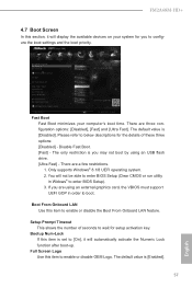
... purchasing ASRock FM2A68M-HD+ motherboard, a reliable motherboard produced under ASRock's consistently stringent quality control. It delivers excellent performance with robust design conforming to ASRock's commitment to this manual occur, the updated version will be available on ASRock website as well. Because the motherboard speciications and the BIOS software might be updated, the content of the BIOS setup. ASRock website...
... purchasing ASRock FM2A68M-HD+ motherboard, a reliable motherboard produced under ASRock's consistently stringent quality control. It delivers excellent performance with robust design conforming to ASRock's commitment to this manual occur, the updated version will be available on ASRock website as well. Because the motherboard speciications and the BIOS software might be updated, the content of the BIOS setup. ASRock website...

User Manual
Page 8
Storage Connector BIOS Feature Hardware Monitor OS • 4 x SATA3 6.0 Gb/s Connectors, support RAID (RAID 0, RAID 1 and RAID 10), NCQ, AHCI and Hot Plug • 1 x Print Port Header • 1 x ...; 1 x Front Panel Audio Connector • 2 x USB 2.0 Headers (Support 4 USB 2.0 ports) (Supports ESD Protection (ASRock Full Spike Protection)) • 1 x USB 3.0 Header by ASMedia ASM1042A (Supports 2 USB 3.0 ports) (Supports ESD Protection (ASRock Full Spike Protection)) • 64Mb AMI UEFI Legal BIOS with GUI support • Supports "Plug and Play" • ACPI 1.1 Compliant wake up events...
Storage Connector BIOS Feature Hardware Monitor OS • 4 x SATA3 6.0 Gb/s Connectors, support RAID (RAID 0, RAID 1 and RAID 10), NCQ, AHCI and Hot Plug • 1 x Print Port Header • 1 x ...; 1 x Front Panel Audio Connector • 2 x USB 2.0 Headers (Support 4 USB 2.0 ports) (Supports ESD Protection (ASRock Full Spike Protection)) • 1 x USB 3.0 Header by ASMedia ASM1042A (Supports 2 USB 3.0 ports) (Supports ESD Protection (ASRock Full Spike Protection)) • 64Mb AMI UEFI Legal BIOS with GUI support • Supports "Plug and Play" • ACPI 1.1 Compliant wake up events...
User Manual
Page 9
... modules. You can use . 3. quired) * For detailed product information, please visit our website: http://www.asrock.com WARNING Please realize that Windows® cannot use ASRock XFast RAM to utilize the memory that there is no such limitation. We are only supported under Windows®...risk and expense. Overclocking may be enabled only if the display supports 12bpc in the BIOS, applying Untied Overclocking Technology, or using third-party overclocking tools. ASRock website http://www.asrock.com 2. FM2A68M-HD+ Certiications • FCC, CE, WHQL • ErP/EuP Ready (ErP/EuP...
... modules. You can use . 3. quired) * For detailed product information, please visit our website: http://www.asrock.com WARNING Please realize that Windows® cannot use ASRock XFast RAM to utilize the memory that there is no such limitation. We are only supported under Windows®...risk and expense. Overclocking may be enabled only if the display supports 12bpc in the BIOS, applying Untied Overclocking Technology, or using third-party overclocking tools. ASRock website http://www.asrock.com 2. FM2A68M-HD+ Certiications • FCC, CE, WHQL • ErP/EuP Ready (ErP/EuP...

User Manual
Page 10
TPMS1 1 AT X P W R 1 1.3 Motherboard Layout CPU_FAN1 USB 2.0 T: USB1 B: USB2 PS2 Keyboard /Mouse DVI1 PCI Express 3.0 DDR3_A1 (64 bit, 240-pin module) DDR3_B1 (64 bit, 240-pin module) SOCKET FM2b PWR_FAN1 VGA1 USB 3.0 T: USB3 B: USB4 HDMI1 USB 2.0 T: USB5 B: USB6 RJ-45 LAN HD_AUDIO1 1 FM2A68M-HD+ PCIE1 CI1 1 64Mb BIOS 1 CHA_FAN1 SATA_2 SATA_1 AMD A68H (Bolton-D2H) Chipset USB_7_8 USB_9_10 USB_11_12 SATA_4 SATA_3 English 6
TPMS1 1 AT X P W R 1 1.3 Motherboard Layout CPU_FAN1 USB 2.0 T: USB1 B: USB2 PS2 Keyboard /Mouse DVI1 PCI Express 3.0 DDR3_A1 (64 bit, 240-pin module) DDR3_B1 (64 bit, 240-pin module) SOCKET FM2b PWR_FAN1 VGA1 USB 3.0 T: USB3 B: USB4 HDMI1 USB 2.0 T: USB5 B: USB6 RJ-45 LAN HD_AUDIO1 1 FM2A68M-HD+ PCIE1 CI1 1 64Mb BIOS 1 CHA_FAN1 SATA_2 SATA_1 AMD A68H (Bolton-D2H) Chipset USB_7_8 USB_9_10 USB_11_12 SATA_4 SATA_3 English 6

User Manual
Page 19
... in CMOS. To clear and reset the system parameters to clear the record of previous chassis intrusion status. However, please do the clear-CMOS action. FM2A68M-HD+ 2.5 Jumpers Setup The illustration shows how jumpers are "Short" when jumper cap is placed on pins, the jumper is "Short". Please be noted that... you clear the CMOS, the case open may be cleared only if the CMOS battery is placed on CLRCMOS1 for 5 seconds. Please adjust the BIOS option "Clear Status" to default setup, please turn off the computer and unplug the power cord from the power supply. If no jumper cap ...
... in CMOS. To clear and reset the system parameters to clear the record of previous chassis intrusion status. However, please do the clear-CMOS action. FM2A68M-HD+ 2.5 Jumpers Setup The illustration shows how jumpers are "Short" when jumper cap is placed on pins, the jumper is "Short". Please be noted that... you clear the CMOS, the case open may be cleared only if the CMOS battery is placed on CLRCMOS1 for 5 seconds. Please adjust the BIOS option "Clear Status" to default setup, please turn off the computer and unplug the power cord from the power supply. If no jumper cap ...

User Manual
Page 31
English 27 FM2A68M-HD+ Tech Service Contact Tech Service if you have problems with your contact information along with details of BIOS or drivers. Please leave your computer. Live Update Check for newer versions of the problem.
English 27 FM2A68M-HD+ Tech Service Contact Tech Service if you have problems with your contact information along with details of BIOS or drivers. Please leave your computer. Live Update Check for newer versions of the problem.

User Manual
Page 37
Step 2 to see more Click to select one or more items you will see a list of recommended or critical updates for the BIOS or drivers. Please update them all soon. Step 3 Click Update to start the update process. 33 English FM2A68M-HD+ 3.3.3 BIOS & Drivers Installing BIOS or Drivers When the "BIOS & Drivers" tab is selected, you want to update. Click on details. Step 1 Please check the item information before update.
Step 2 to see more Click to select one or more items you will see a list of recommended or critical updates for the BIOS or drivers. Please update them all soon. Step 3 Click Update to start the update process. 33 English FM2A68M-HD+ 3.3.3 BIOS & Drivers Installing BIOS or Drivers When the "BIOS & Drivers" tab is selected, you want to update. Click on details. Step 1 Please check the item information before update.

User Manual
Page 42
The UEFI chip on . If you wish to enter the UEFI SETUP UTILITY, otherwise, POST will it make BIOS setup less dificult but also a lot more amusing. UEFI SETUP UTILITY 4.1 Introduction ASRock Interactive UEFI is constantly being updated, the following UEFI setup screens and descriptions are for reference purpose only, and they may...
The UEFI chip on . If you wish to enter the UEFI SETUP UTILITY, otherwise, POST will it make BIOS setup less dificult but also a lot more amusing. UEFI SETUP UTILITY 4.1 Introduction ASRock Interactive UEFI is constantly being updated, the following UEFI setup screens and descriptions are for reference purpose only, and they may...

User Manual
Page 51
4.4.4 Storage Coniguration FM2A68M-HD+ SATA Controller Use this item to enable or disable AMD AHCI BIOS ROM. Coniguration options: [AHCI Mode], [RAID Mode] and [IDE Mode]. AMD AHCI BIOS ROM Use this item to enable or disable the "SATA Controller" feature. The default value of this item to adjust SATA Mode. Use this option ...
4.4.4 Storage Coniguration FM2A68M-HD+ SATA Controller Use this item to enable or disable AMD AHCI BIOS ROM. Coniguration options: [AHCI Mode], [RAID Mode] and [IDE Mode]. AMD AHCI BIOS ROM Use this item to enable or disable the "SATA Controller" feature. The default value of this item to adjust SATA Mode. Use this option ...
User Manual
Page 61
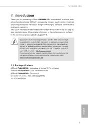
...Logo Use this item to conigure the boot settings and the boot priority. You will not be able to enter BIOS Setup (Clear CMOS or run utility in order to enter BIOS Setup). 3. Bootup Num-Lock If this item is you are a few restrictions. 1. The default value is [...to boot. There are using an USB lash drive. [Ultra Fast] - Setup Prompt Timeout This shows the number of these three options: [Disabled] - FM2A68M-HD+ 4.7 Boot Screen In this section, it will automatically activate the Numeric Lock function after boot-up. There are three coniguration options: [Disabled], [Fast] and...
...Logo Use this item to conigure the boot settings and the boot priority. You will not be able to enter BIOS Setup (Clear CMOS or run utility in order to enter BIOS Setup). 3. Bootup Num-Lock If this item is you are a few restrictions. 1. The default value is [...to boot. There are using an USB lash drive. [Ultra Fast] - Setup Prompt Timeout This shows the number of these three options: [Disabled] - FM2A68M-HD+ 4.7 Boot Screen In this section, it will automatically activate the Numeric Lock function after boot-up. There are three coniguration options: [Disabled], [Fast] and...

User Manual
Page 62
... the bootsequence. [Keep Current] - Do not launch? The third-party ROM messages will be forced to launch the Compatibility Support Module. Option ROM Messages [Force BIOS] - The third-party ROM messages will be displayed only if the third-partymanufacturer had set the add-on device to run those that support UEFI...
... the bootsequence. [Keep Current] - Do not launch? The third-party ROM messages will be forced to launch the Compatibility Support Module. Option ROM Messages [Force BIOS] - The third-party ROM messages will be displayed only if the third-partymanufacturer had set the add-on device to run those that support UEFI...

Quick Installation Guide
Page 3
Motherboard Layout FM2A68M-HD+ USB 2.0 T: USB1 B: USB2 PS2 Keyboard /Mouse TPMS1 1 AT X P W R 1 CPU_FAN1 DVI1 PCI Express 3.0 DDR3_A1 (64 bit, 240-pin module) DDR3_B1 (64 bit, 240-pin module) SOCKET FM2b PWR_FAN1 VGA1 USB 3.0 T: USB3 B: USB4 HDMI1 USB 2.0 T: USB5 B: USB6 RJ-45 LAN HD_AUDIO1 1 FM2A68M-HD+ PCIE1 CI1 1 64Mb BIOS 1 CHA_FAN1 SATA_2 SATA_1 AMD A68H (Bolton-D2H) Chipset USB_7_8 USB_9_10 USB_11_12 SATA_4 SATA_3 English 1
Motherboard Layout FM2A68M-HD+ USB 2.0 T: USB1 B: USB2 PS2 Keyboard /Mouse TPMS1 1 AT X P W R 1 CPU_FAN1 DVI1 PCI Express 3.0 DDR3_A1 (64 bit, 240-pin module) DDR3_B1 (64 bit, 240-pin module) SOCKET FM2b PWR_FAN1 VGA1 USB 3.0 T: USB3 B: USB4 HDMI1 USB 2.0 T: USB5 B: USB6 RJ-45 LAN HD_AUDIO1 1 FM2A68M-HD+ PCIE1 CI1 1 64Mb BIOS 1 CHA_FAN1 SATA_2 SATA_1 AMD A68H (Bolton-D2H) Chipset USB_7_8 USB_9_10 USB_11_12 SATA_4 SATA_3 English 1
Quick Installation Guide
Page 7
... support related to this motherboard, please visit our website for purchasing ASRock FM2A68M-HD+ motherboard, a reliable motherboard produced under ASRock's consistently stringent quality control. Because the motherboard speciications and the BIOS software might be updated, the content of this manual will be available on ASRock website as well. This Quick Installation Guide contains introduction of the...
... support related to this motherboard, please visit our website for purchasing ASRock FM2A68M-HD+ motherboard, a reliable motherboard produced under ASRock's consistently stringent quality control. Because the motherboard speciications and the BIOS software might be updated, the content of this manual will be available on ASRock website as well. This Quick Installation Guide contains introduction of the...

Quick Installation Guide
Page 10
Storage Connector BIOS Feature Hardware Monitor OS • 4 x SATA3 6.0 Gb/s Connectors, support RAID (RAID 0, RAID 1 and RAID 10), NCQ, AHCI and Hot Plug • 1 x Print Port Header • 1 x ...; 1 x Front Panel Audio Connector • 2 x USB 2.0 Headers (Support 4 USB 2.0 ports) (Supports ESD Protection (ASRock Full Spike Protection)) • 1 x USB 3.0 Header by ASMedia ASM1042A (Supports 2 USB 3.0 ports) (Supports ESD Protection (ASRock Full Spike Protection)) • 64Mb AMI UEFI Legal BIOS with GUI support • Supports "Plug and Play" • ACPI 1.1 Compliant wake up events...
Storage Connector BIOS Feature Hardware Monitor OS • 4 x SATA3 6.0 Gb/s Connectors, support RAID (RAID 0, RAID 1 and RAID 10), NCQ, AHCI and Hot Plug • 1 x Print Port Header • 1 x ...; 1 x Front Panel Audio Connector • 2 x USB 2.0 Headers (Support 4 USB 2.0 ports) (Supports ESD Protection (ASRock Full Spike Protection)) • 1 x USB 3.0 Header by ASMedia ASM1042A (Supports 2 USB 3.0 ports) (Supports ESD Protection (ASRock Full Spike Protection)) • 64Mb AMI UEFI Legal BIOS with GUI support • Supports "Plug and Play" • ACPI 1.1 Compliant wake up events...

Quick Installation Guide
Page 11
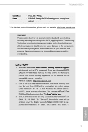
... Color are not responsible for possible damage caused by overclocking. Deep Color mode will be done at your system. ASRock website http://www.asrock.com 2. You can use . 3. FM2A68M-HD+ Certiications • FCC, CE, WHQL • ErP/EuP Ready (ErP/EuP ready power supply is a ...174; 8.1 64-bit / 8.1 / 8 64-bit / 8 / 7 64-bit / 7. It should be enabled only if the display supports 12bpc in the BIOS, applying Untied Overclocking Technology, or using third-party overclocking tools. Whether 2400/2133/1866/1600MHz memory speed is supported under Windows® 8.1 64-bit / 8.1 /...
... Color are not responsible for possible damage caused by overclocking. Deep Color mode will be done at your system. ASRock website http://www.asrock.com 2. You can use . 3. FM2A68M-HD+ Certiications • FCC, CE, WHQL • ErP/EuP Ready (ErP/EuP ready power supply is a ...174; 8.1 64-bit / 8.1 / 8 64-bit / 8 / 7 64-bit / 7. It should be enabled only if the display supports 12bpc in the BIOS, applying Untied Overclocking Technology, or using third-party overclocking tools. Whether 2400/2133/1866/1600MHz memory speed is supported under Windows® 8.1 64-bit / 8.1 /...

Quick Installation Guide
Page 12
... from the power supply. If you need to clear the CMOS when you just inish updating the BIOS, you must boot up the system irst, and then shut it down before you do not clear... CMOS, the case open may be cleared only if the CMOS battery is "Short". If you update the BIOS. After waiting for 15 seconds, use a jumper cap to clear the record of previous chassis intrusion status....the data in CMOS. When the jumper cap is placed on pins, the jumper is removed. Please adjust the BIOS option "Clear Status" to short pin2 and pin3 on these 2 pins. The illustration shows a 3-pin jumper ...
... from the power supply. If you need to clear the CMOS when you just inish updating the BIOS, you must boot up the system irst, and then shut it down before you do not clear... CMOS, the case open may be cleared only if the CMOS battery is "Short". If you update the BIOS. After waiting for 15 seconds, use a jumper cap to clear the record of previous chassis intrusion status....the data in CMOS. When the jumper cap is placed on pins, the jumper is removed. Please adjust the BIOS option "Clear Status" to short pin2 and pin3 on these 2 pins. The illustration shows a 3-pin jumper ...

Quick Installation Guide
Page 55
FM2A68M-HD+ 繁體中文 Rear Panel I/O BIOS • 5.1 Realtek ALC662 ASRock 全防護 ) • PCIE x1 Gigabit LAN 10/100/1000 Mb/s • Realtek RTL8111GR Wake-On-WAN Wake-On-LAN ESD 靜電 (ASRock Energy...2.0 4 USB 2.0 接口 ) 1 x ASMedia ASM1042A 的 USB 3.0 2 個額外 的 USB 3.0 ESD • 64Mb AMI BIOS • AMI UEFI Legal BIOS ( 支援 GUI) Plug and Play,PnP) • ACPI 1.1 • 支援 jumperfree • DRAM、CPU 53
FM2A68M-HD+ 繁體中文 Rear Panel I/O BIOS • 5.1 Realtek ALC662 ASRock 全防護 ) • PCIE x1 Gigabit LAN 10/100/1000 Mb/s • Realtek RTL8111GR Wake-On-WAN Wake-On-LAN ESD 靜電 (ASRock Energy...2.0 4 USB 2.0 接口 ) 1 x ASMedia ASM1042A 的 USB 3.0 2 個額外 的 USB 3.0 ESD • 64Mb AMI BIOS • AMI UEFI Legal BIOS ( 支援 GUI) Plug and Play,PnP) • ACPI 1.1 • 支援 jumperfree • DRAM、CPU 53

RAID Installation Guide
Page 1
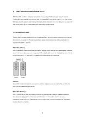
AMD BIOS RAID Installation Guide ...2 1.1 Introduction to Create RAID Array in Windows (for AMD A88X/A78/A68H/A58 Chipset) ...27 Appendix -rcadm.efi information for AMD A88X, ...
AMD BIOS RAID Installation Guide ...2 1.1 Introduction to Create RAID Array in Windows (for AMD A88X/A78/A68H/A58 Chipset) ...27 Appendix -rcadm.efi information for AMD A88X, ...
RAID Installation Guide
Page 2
...Utility to configure RAID. 1.1 Introduction to RAID The term "RAID" stands for you to configure RAID functions by using the onboard FastBuild BIOS utility under BIOS environment. RAID 0 (Data Striping) RAID 0 is called data striping that copies and maintains an identical image of the data in ...optimizes two identical hard disk drives to the surviving drive as a single drive but at a sustained data transfer rate. AMD BIOS RAID Installation Guide AMD BIOS RAID Installation Guide is an instruction for "Redundant Array of the same model and capacity when creating a RAID set the ...
...Utility to configure RAID. 1.1 Introduction to RAID The term "RAID" stands for you to configure RAID functions by using the onboard FastBuild BIOS utility under BIOS environment. RAID 0 (Data Striping) RAID 0 is called data striping that copies and maintains an identical image of the data in ...optimizes two identical hard disk drives to the surviving drive as a single drive but at a sustained data transfer rate. AMD BIOS RAID Installation Guide AMD BIOS RAID Installation Guide is an instruction for "Redundant Array of the same model and capacity when creating a RAID set the ...

RAID Installation Guide
Page 9
...Follow the instruction inside your Windows version (Windows 7/8/8.1). After copying RAID driver to a USB flash drive, please set the "SATA Mode" option to in BIOS setup. C. Follow instructions to enter UEFI setup utility. B. For 64bit OS, the driver is under /AMD64 directly. E. Set the "SATA Mode" ... a USB flash drive A. B. After RAID driver is limited to Tools Easy RAID Installer F. The RAID disk will be created in BIOS setup. Insert the Support CD into the DVD-ROM drive. During Windows installation process, when Disk selection page show up , please click ....
...Follow the instruction inside your Windows version (Windows 7/8/8.1). After copying RAID driver to a USB flash drive, please set the "SATA Mode" option to in BIOS setup. C. Follow instructions to enter UEFI setup utility. B. For 64bit OS, the driver is under /AMD64 directly. E. Set the "SATA Mode" ... a USB flash drive A. B. After RAID driver is limited to Tools Easy RAID Installer F. The RAID disk will be created in BIOS setup. Insert the Support CD into the DVD-ROM drive. During Windows installation process, when Disk selection page show up , please click ....


