
RAID Installation Guide
Page 6
... components of this physical drive. For RAID levels 1, 5, and 10, the logical drive contains a failed physical drive. The AMD motherboard port ID number to it displays pertinent information about the RAID logical drives that monitors the condition of three logical drive conditions: Functional ...- Port - The manufacturer's name and model number of the AMD motherboard. 1.4 Opening Option ROM The Option ROM and the Option ROM Utility are present. When the Option ROM loads during boot-up,...
... components of this physical drive. For RAID levels 1, 5, and 10, the logical drive contains a failed physical drive. The AMD motherboard port ID number to it displays pertinent information about the RAID logical drives that monitors the condition of three logical drive conditions: Functional ...- Port - The manufacturer's name and model number of the AMD motherboard. 1.4 Opening Option ROM The Option ROM and the Option ROM Utility are present. When the Option ROM loads during boot-up,...

RAID Installation Guide
Page 8
...Disk. An extent is connected. This screen reports physical drive assignments and provides the following information: Port: ID - S.M.A.R.T. Shows the AMD motherboard port ID number to which a particular physical drive is OK. The portion of the physical drive. Reflects the capacity in a logical drive... the disk drive is attached. The sum of the two extents is slightly smaller than the total capacity of ports depends on the motherboard and whether a port multiplier is a portion of a physical drive between two logical drives. The type and speed of each physical drive...
...Disk. An extent is connected. This screen reports physical drive assignments and provides the following information: Port: ID - S.M.A.R.T. Shows the AMD motherboard port ID number to which a particular physical drive is OK. The portion of the physical drive. Reflects the capacity in a logical drive... the disk drive is attached. The sum of the two extents is slightly smaller than the total capacity of ports depends on the motherboard and whether a port multiplier is a portion of a physical drive between two logical drives. The type and speed of each physical drive...

User Manual
Page 2
... this manual may or may apply, see www.dtsc.ca.gov/hazardouswaste/perchlorate" ASRock Website: http://www.asrock.com 2 CALIFORNIA, USA ONLY The Lithium battery adopted on this motherboard contains Perchlorate, a toxic substance controlled in Perchlorate Best Management Practices (BMP) regulations... passed by ASRock. With respect to the contents of this manual, ASRock does not provide warranty of any kind, either ...
... this manual may or may apply, see www.dtsc.ca.gov/hazardouswaste/perchlorate" ASRock Website: http://www.asrock.com 2 CALIFORNIA, USA ONLY The Lithium battery adopted on this motherboard contains Perchlorate, a toxic substance controlled in Perchlorate Best Management Practices (BMP) regulations... passed by ASRock. With respect to the contents of this manual, ASRock does not provide warranty of any kind, either ...

User Manual
Page 3
Introduction 5 1.1 Package Contents 5 1.2 Specifications 6 1.3 Unique Features 9 1.4 Motherboard Layout 13 1.5 I/O Panel 14 2. Installation 15 Pre-installation Precautions 15 2.1 CPU Installation 16 2.2 Installation of CPU Fan and Heatsink 16 2.3 Installation of Memory Modules (DIMM ...
Introduction 5 1.1 Package Contents 5 1.2 Specifications 6 1.3 Unique Features 9 1.4 Motherboard Layout 13 1.5 I/O Panel 14 2. Installation 15 Pre-installation Precautions 15 2.1 CPU Installation 16 2.2 Installation of CPU Fan and Heatsink 16 2.3 Installation of Memory Modules (DIMM ...
User Manual
Page 5
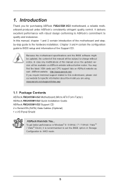
... website for specific information about the model you for purchasing ASRock FM2A55M-VG3 motherboard, a reliable motherboard produced under ASRock's consistently stringent quality control. www.asrock.com/support/index.asp 1.1 Package Contents ASRock FM2A55M-VG3 Motherboard (Micro ATX Form Factor) ASRock FM2A55M-VG3 Quick Installation Guide ASRock FM2A55M-VG3 Support CD 2 x Serial ATA (SATA) Data Cables (Optional) 1 x I/O Panel Shield ASRock Reminds You... You may find the latest VGA cards...
... website for specific information about the model you for purchasing ASRock FM2A55M-VG3 motherboard, a reliable motherboard produced under ASRock's consistently stringent quality control. www.asrock.com/support/index.asp 1.1 Package Contents ASRock FM2A55M-VG3 Motherboard (Micro ATX Form Factor) ASRock FM2A55M-VG3 Quick Installation Guide ASRock FM2A55M-VG3 Support CD 2 x Serial ATA (SATA) Data Cables (Optional) 1 x I/O Panel Shield ASRock Reminds You... You may find the latest VGA cards...
User Manual
Page 8
If you want to adopt DDR3 1866/1600 memory module on this motherboard, please refer to the operating system limitation, the actual memory size may be less than 4GB for the reservation for details. 8 ASRock website http://www.asrock.com 2. You can use ASRock XFast RAM to http://www.amd.com/us/products/technologies/ dual...
If you want to adopt DDR3 1866/1600 memory module on this motherboard, please refer to the operating system limitation, the actual memory size may be less than 4GB for the reservation for details. 8 ASRock website http://www.asrock.com 2. You can use ASRock XFast RAM to http://www.amd.com/us/products/technologies/ dual...
User Manual
Page 11
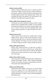
...support this function. ASRock UEFI System Browser ASRock UEFI system browser is a useful tool included in UEFI setup. ASRock Dehumidifier Function Users may schedule the starting and ending hours of internet access granted to dampness by enabling "Dehumidifier Function". You may prevent motherboard damages due to ... Dehumidifier Function, the computer will automatically finish the BIOS update procedure after entering S4/S5 state. ASRock Crashless BIOS ASRock Crashless BIOS allows users to dehumidify the system after regaining power. If power loss occurs during the BIOS update process...
...support this function. ASRock UEFI System Browser ASRock UEFI system browser is a useful tool included in UEFI setup. ASRock Dehumidifier Function Users may schedule the starting and ending hours of internet access granted to dampness by enabling "Dehumidifier Function". You may prevent motherboard damages due to ... Dehumidifier Function, the computer will automatically finish the BIOS update procedure after entering S4/S5 state. ASRock Crashless BIOS ASRock Crashless BIOS allows users to dehumidify the system after regaining power. If power loss occurs during the BIOS update process...
User Manual
Page 13
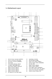
1.4 Motherboard Layout 1 2 3 45 6 22 CI1 1 CPU_FAN1 AT X P W R 1 PS2 Mouse PS2 Keyboard ATX12V1 DDR3_B1 (64 bit, 240-pin module) DDR3_A1 (64 bit, 240-FpinSBmo8d0ul0e) DDR3 VGA1 SOCKET ... USB 2.0 T: USB2 B: USB3 8 RJ-45 LAN SATA_3 X Fast RAM SATA_2 LAN 9 X Fast LAN CHA_FAN1 10 SATA_1 Top: LINE IN Center: FRONT Bottom: MIC IN 21 FM2A55M-VG3 20 1 RoHS HD_AUDIO1 CMOS BATTERY PCIE1 11 19 18 AUDIO CODEC 1 CLRCMOS1 1 USB6_7 1 USB4_5 X Fast USB Super I/O PCI1 AMD A55 FCH (Hudson-D2) Chipset 64Mb...
1.4 Motherboard Layout 1 2 3 45 6 22 CI1 1 CPU_FAN1 AT X P W R 1 PS2 Mouse PS2 Keyboard ATX12V1 DDR3_B1 (64 bit, 240-pin module) DDR3_A1 (64 bit, 240-FpinSBmo8d0ul0e) DDR3 VGA1 SOCKET ... USB 2.0 T: USB2 B: USB3 8 RJ-45 LAN SATA_3 X Fast RAM SATA_2 LAN 9 X Fast LAN CHA_FAN1 10 SATA_1 Top: LINE IN Center: FRONT Bottom: MIC IN 21 FM2A55M-VG3 20 1 RoHS HD_AUDIO1 CMOS BATTERY PCIE1 11 19 18 AUDIO CODEC 1 CLRCMOS1 1 USB6_7 1 USB4_5 X Fast USB Super I/O PCI1 AMD A55 FCH (Hudson-D2) Chipset 64Mb...

User Manual
Page 15
... before you install or remove any component. 2. Pre-installation Precautions Take note of the following precautions before you install the motherboard, study the configuration of your motherboard directly on a grounded antistatic pad or in the bag that comes with the component. 5. Failure to use a grounded ...wrist strap or touch a safety grounded object before touching any component, ensure that the motherboard fits into the screw holes to secure the motherboard to ensure that the power is switched off or the power cord is a Micro ATX form factor...
... before you install or remove any component. 2. Pre-installation Precautions Take note of the following precautions before you install the motherboard, study the configuration of your motherboard directly on a grounded antistatic pad or in the bag that comes with the component. 5. Failure to use a grounded ...wrist strap or touch a safety grounded object before touching any component, ensure that the motherboard fits into the screw holes to secure the motherboard to ensure that the power is switched off or the power cord is a Micro ATX form factor...

User Manual
Page 16
... the pins. Carefully insert the CPU into the socket to dissipate heat. The lever clicks on the socket while you install the CPU into this motherboard, it is locked. Unlock the socket by lifting the lever up to improve heat dissipation. You also need to spray thermal grease between the CPU...
... the pins. Carefully insert the CPU into the socket to dissipate heat. The lever clicks on the socket while you install the CPU into this motherboard, it is locked. Unlock the socket by lifting the lever up to improve heat dissipation. You also need to spray thermal grease between the CPU...

User Manual
Page 17
...Align a DIMM on the slot such that the notch on the DIMM matches the break on the slot. It will cause permanent damage to the motherboard and the DIMM if you always need to install two identical (the same brand, speed, size and chiptype) memory modules in the DDR3 DIMM...back in one memory module or two non-identical memory modules, it will operate at single channel mode. 1. 2.3 Installation of Memory Modules (DIMM) This motherboard provides two 240-pin DDR3 (Double Data Rate 3) DIMM slots, and supports Dual Channel Memory Technology. Unlock a DIMM slot by pressing the retaining clips...
...Align a DIMM on the slot such that the notch on the DIMM matches the break on the slot. It will cause permanent damage to the motherboard and the DIMM if you always need to install two identical (the same brand, speed, size and chiptype) memory modules in the DDR3 DIMM...back in one memory module or two non-identical memory modules, it will operate at single channel mode. 1. 2.3 Installation of Memory Modules (DIMM) This motherboard provides two 240-pin DDR3 (Double Data Rate 3) DIMM slots, and supports Dual Channel Memory Technology. Unlock a DIMM slot by pressing the retaining clips...

User Manual
Page 18
... Slots) There is 1 PCI slot and 1 PCI Express slot on the slot. Keep the screws for later use . Remove the system unit cover (if your motherboard is unplugged. Before installing the expansion card, please make necessary hardware settings for PCI Express x16 lane width graphics cards. Replace the system cover. 18... are used for the card before you intend to the chassis with the slot and press firmly until the card is completely seated on this motherboard.
... Slots) There is 1 PCI slot and 1 PCI Express slot on the slot. Keep the screws for later use . Remove the system unit cover (if your motherboard is unplugged. Before installing the expansion card, please make necessary hardware settings for PCI Express x16 lane width graphics cards. Replace the system cover. 18... are used for the card before you intend to the chassis with the slot and press firmly until the card is completely seated on this motherboard.
User Manual
Page 19
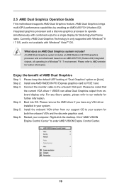
..." to the onboard VGA port. Right-click the desktop. An AMD Dual Graphics system includes an AMD Radeon HD 7000 graphics processor and a motherboard based on [Auto]. Boot into OS. Install the onboard VGA driver from onboard display only. 2.5 AMD Dual Graphics Operation Guide This... motherboard supports AMD Dual Graphics feature. Please keep the default UEFI setting of AMD Dual Graphics Step 1. Install one AMD RADEON PCI Express graphics card ...
..." to the onboard VGA port. Right-click the desktop. An AMD Dual Graphics system includes an AMD Radeon HD 7000 graphics processor and a motherboard based on [Auto]. Boot into OS. Install the onboard VGA driver from onboard display only. 2.5 AMD Dual Graphics Operation Guide This... motherboard supports AMD Dual Graphics feature. Please keep the default UEFI setting of AMD Dual Graphics Step 1. Install one AMD RADEON PCI Express graphics card ...
User Manual
Page 21
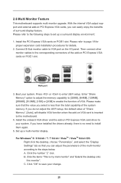
... VGA card driver to the corresponding connectors of the multi-monitor according to install them again. 5. A. 2.6 Multi Monitor Feature This motherboard supports multi monitor upgrade. Then connect other monitor cables to your system. If you can adjust the parameters of the add-on PCI... Express VGA cards on PCI Express VGA cards, you have installed the drivers already, there is my main monitor" and "Extend the desktop onto this motherboard. 4. For Windows® 8 / 8 64-bit / 7 / 7 64-bit / VistaTM / VistaTM 64-bit OS: Right click the desktop, choose "Personalize", and...
... VGA card driver to the corresponding connectors of the multi-monitor according to install them again. 5. A. 2.6 Multi Monitor Feature This motherboard supports multi monitor upgrade. Then connect other monitor cables to your system. If you can adjust the parameters of the add-on PCI... Express VGA cards on PCI Express VGA cards, you have installed the drivers already, there is my main monitor" and "Extend the desktop onto this motherboard. 4. For Windows® 8 / 8 64-bit / 7 / 7 64-bit / VistaTM / VistaTM 64-bit OS: Right click the desktop, choose "Personalize", and...

User Manual
Page 24
... p.13, No. 9) (SATA_3: see p.13, No. 8) (SATA_4: see p.13 No. 18) USB_PWR P-7 P+7 GND DUMMY 1 GND P+6 P-6 USB_PWR Either end of the motherboard! SATA_1 Serial ATA (SATA) Data Cable (Optional) USB 2.0 Headers (9-pin USB4_5) (see p.13 No. 17) (9-pin USB6_7) (see p.13, No. 7) SATA_4 SATA_3 SATA_2 ...connected to 3.0 Gb/s data transfer rate. 2.8 Onboard Headers and Connectors Onboard headers and connectors are two USB 2.0 headers on this motherboard. Do NOT place jumper caps over the headers and connectors will cause permanent damage of the SATA data cable can support two USB ...
... p.13, No. 9) (SATA_3: see p.13, No. 8) (SATA_4: see p.13 No. 18) USB_PWR P-7 P+7 GND DUMMY 1 GND P+6 P-6 USB_PWR Either end of the motherboard! SATA_1 Serial ATA (SATA) Data Cable (Optional) USB 2.0 Headers (9-pin USB4_5) (see p.13 No. 17) (9-pin USB6_7) (see p.13, No. 7) SATA_4 SATA_3 SATA_2 ...connected to 3.0 Gb/s data transfer rate. 2.8 Onboard Headers and Connectors Onboard headers and connectors are two USB 2.0 headers on this motherboard. Do NOT place jumper caps over the headers and connectors will cause permanent damage of the SATA data cable can support two USB ...
User Manual
Page 26
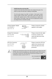
... of power switch, reset switch, power LED, hard drive activity LED, speaker and etc. When connecting your chassis front panel module to this motherboard, please connect it to this motherboard provides 4-Pin CPU fan (Quiet Fan) support, the 3-Pin CPU fan still can work successfully even without the fan speed control function...
... of power switch, reset switch, power LED, hard drive activity LED, speaker and etc. When connecting your chassis front panel module to this motherboard, please connect it to this motherboard provides 4-Pin CPU fan (Quiet Fan) support, the 3-Pin CPU fan still can work successfully even without the fan speed control function...

User Manual
Page 27
... this connector. ATX Power Connector 24 (24-pin ATXPWR1) (see p.13 No. 3) 12 Please connect an ATX power 13 supply to this motherboard provides 24-pin ATX power connector, it can still work if you adopt a traditional 20-pin ATX power supply. This feature requires a chassis ...13 20-Pin ATX Power Supply Installation 12 1 ATX 12V Power Connector (4-pin ATX12V1) (see p.13, No. 22) 1 GND Signal This motherboard supports CASE OPEN detection feature that detects if the chassis cover has been removed. To use the 20-pin ATX power supply, please plug your...
... this connector. ATX Power Connector 24 (24-pin ATXPWR1) (see p.13 No. 3) 12 Please connect an ATX power 13 supply to this motherboard provides 24-pin ATX power connector, it can still work if you adopt a traditional 20-pin ATX power supply. This feature requires a chassis ...13 20-Pin ATX Power Supply Installation 12 1 ATX 12V Power Connector (4-pin ATX12V1) (see p.13, No. 22) 1 GND Signal This motherboard supports CASE OPEN detection feature that detects if the chassis cover has been removed. To use the 20-pin ATX power supply, please plug your...
User Manual
Page 28
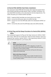
STEP 2: Connect the SATA power cable to the SATA2 hard disk. 2.10 Hot Plug and Hot Swap Functions for Serial ATA2 (SATA2) HDDs This motherboard supports Hot Plug and Hot Swap functions for SATA2 in RAID / AHCI mode. STEP 4: Connect the other end of the SATA data cable to the ... disk. However, please note that supports Serial ATA2 (SATA2) hard disks and RAID (RAID 0, RAID 1 and RAID 10) functions. What is still power-on this motherboard for the action to insert and remove the SATA2 HDDs while the system is Hot Plug Function? STEP 1: Install the SATA2 hard disks into the...
STEP 2: Connect the SATA power cable to the SATA2 hard disk. 2.10 Hot Plug and Hot Swap Functions for Serial ATA2 (SATA2) HDDs This motherboard supports Hot Plug and Hot Swap functions for SATA2 in RAID / AHCI mode. STEP 4: Connect the other end of the SATA data cable to the ... disk. However, please note that supports Serial ATA2 (SATA2) hard disks and RAID (RAID 0, RAID 1 and RAID 10) functions. What is still power-on this motherboard for the action to insert and remove the SATA2 HDDs while the system is Hot Plug Function? STEP 1: Install the SATA2 hard disks into the...
User Manual
Page 29
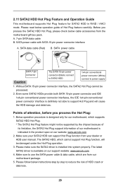
.... The SATA2 HDD, which are from our motherboard package. 5. Please make sure the SATA2 driver is available on our website: www.asrock.com 2. 2.11 SATA2 HDD Hot Plug Feature and Operation Guide This motherboard supports Hot Plug feature for our motherboard, which supports SATA2 HDD Hot Plug. * ... SATA 15-pin power connector interface A. Please follow below cable accessories from your SATA2 HDD can support Hot Plug function from the motherboard gift box pack. Points of Hot Plug feature carefully. The latest SATA2 driver is installed into system properly. Make sure to power...
.... The SATA2 HDD, which are from our motherboard package. 5. Please make sure the SATA2 driver is available on our website: www.asrock.com 2. 2.11 SATA2 HDD Hot Plug Feature and Operation Guide This motherboard supports Hot Plug feature for our motherboard, which supports SATA2 HDD Hot Plug. * ... SATA 15-pin power connector interface A. Please follow below cable accessories from your SATA2 HDD can support Hot Plug function from the motherboard gift box pack. Points of Hot Plug feature carefully. The latest SATA2 driver is installed into system properly. Make sure to power...

User Manual
Page 30
...-pin Step 2 Connect SATA data cable to end (White) to the SATA2 HDD. Step 4 Connect SATA data cable to the power supply 1x4-pin the motherboard's SATA2 cable. Step 1 Unplug SATA data cable from SATA2 HDD side. 30 connector. SATA power cable 1x4-pin power connector (White) Step 3 Connect SATA 15...
...-pin Step 2 Connect SATA data cable to end (White) to the SATA2 HDD. Step 4 Connect SATA data cable to the power supply 1x4-pin the motherboard's SATA2 cable. Step 1 Unplug SATA data cable from SATA2 HDD side. 30 connector. SATA power cable 1x4-pin power connector (White) Step 3 Connect SATA 15...

