

User Manual
Page 2
...169;2015 ASRock INC.... subject to the implied warranties or conditions of ASRock Inc. ASRock assumes no event shall ASRock, its directors, officers, employees, or agents ...of data, interruption of business and the like), even if ASRock has been advised of the possibility of the FCC Rules...., see www.dtsc.ca.gov/hazardouswaste/ perchlorate" ASRock Website: http://www.asrock.com "Perchlorate Material-special handling may be constructed as...reserved. Copyright Notice: No part of this documentation, ASRock does not provide warranty of any interference received, including interference that...
...169;2015 ASRock INC.... subject to the implied warranties or conditions of ASRock Inc. ASRock assumes no event shall ASRock, its directors, officers, employees, or agents ...of data, interruption of business and the like), even if ASRock has been advised of the possibility of the FCC Rules...., see www.dtsc.ca.gov/hazardouswaste/ perchlorate" ASRock Website: http://www.asrock.com "Perchlorate Material-special handling may be constructed as...reserved. Copyright Notice: No part of this documentation, ASRock does not provide warranty of any interference received, including interference that...

User Manual
Page 3
Contents Chapter 1 Introduction 1 1.1 Package Contents 1 1.2 Specifications 2 1.3 Motherboard Layout 5 1.4 I/O Panel 7 Chapter 2 Installation 9 2.1 Installing the CPU 10 2.2 Installing the CPU Fan and Heatsink 13 2.3 Installing Memory Modules (DIMM) 14 2.4 Expansion Slots (PCI Express Slots) ... Guide 22 2.7.1 Installing Two CrossFireXTM-Ready Graphics Cards 22 2.7.2 Driver Installation and Setup 24 Chapter 3 Software and Utilities Operation 25 3.1 Installing Drivers 25 3.2 A-Tuning 26 3.3 ASRock Live Update & APP Shop 30 3.3.1 UI Overview 30 3.3.2 Apps 31
Contents Chapter 1 Introduction 1 1.1 Package Contents 1 1.2 Specifications 2 1.3 Motherboard Layout 5 1.4 I/O Panel 7 Chapter 2 Installation 9 2.1 Installing the CPU 10 2.2 Installing the CPU Fan and Heatsink 13 2.3 Installing Memory Modules (DIMM) 14 2.4 Expansion Slots (PCI Express Slots) ... Guide 22 2.7.1 Installing Two CrossFireXTM-Ready Graphics Cards 22 2.7.2 Driver Installation and Setup 24 Chapter 3 Software and Utilities Operation 25 3.1 Installing Drivers 25 3.2 A-Tuning 26 3.3 ASRock Live Update & APP Shop 30 3.3.1 UI Overview 30 3.3.2 Apps 31
User Manual
Page 5
Chapter 3 contains the operation guide of the BIOS setup. ASRock website http://www.asrock.com. 1.1 Package Contents • ASRock E3V5 WS Motherboard (ATX Form Factor) • ASRock E3V5 WS Quick Installation Guide • ASRock E3V5 WS Support CD • 2 x Serial ATA (SATA) Data Cables (Optional) • 1 x I/O Panel Shield 1 English Chapter 4 contains the configuration guide of the software and utilities. You may ...
Chapter 3 contains the operation guide of the BIOS setup. ASRock website http://www.asrock.com. 1.1 Package Contents • ASRock E3V5 WS Motherboard (ATX Form Factor) • ASRock E3V5 WS Quick Installation Guide • ASRock E3V5 WS Support CD • 2 x Serial ATA (SATA) Data Cables (Optional) • 1 x I/O Panel Shield 1 English Chapter 4 contains the configuration guide of the software and utilities. You may ...
User Manual
Page 9
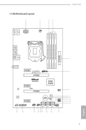
1.3 Motherboard Layout E3V5 WS PS2 Mouse PS2 Keyboard ATX12V1 CPU_FAN1 DDR4_A1 (64 bit, 288-pin module) DDR4_A2 (64 bit, 288-pin module) DDR4_B1 (64 bit, 288-pin module) DDR4_B2 (... B: USB1 USB 3.0 T: USB2 B: USB3 USB 2.0 T: USB0 B: USB1 Top: RJ-45 Top: LINE IN Center: FRONT Bottom: MIC IN PCIE1 Front USB 3.0 1 PCI Express 3.0 PCIE2 USB3_4_5 E3V5 WS PCIE3 RoHS LAN PCIE4 Intel C232 CHA_FAN1 AUDIO CODEC HD_AUDIO1 1 PCIE5 TPMS1 1 USB4_5 1 USB2_3 1 CMOS Battery BIOS 1 CLRMOS1 SATA3_4 SATA3_2 SATA3_0 CHA_FAN2 SPK_PLED1 1 SATA3_5 SATA3_3...
1.3 Motherboard Layout E3V5 WS PS2 Mouse PS2 Keyboard ATX12V1 CPU_FAN1 DDR4_A1 (64 bit, 288-pin module) DDR4_A2 (64 bit, 288-pin module) DDR4_B1 (64 bit, 288-pin module) DDR4_B2 (... B: USB1 USB 3.0 T: USB2 B: USB3 USB 2.0 T: USB0 B: USB1 Top: RJ-45 Top: LINE IN Center: FRONT Bottom: MIC IN PCIE1 Front USB 3.0 1 PCI Express 3.0 PCIE2 USB3_4_5 E3V5 WS PCIE3 RoHS LAN PCIE4 Intel C232 CHA_FAN1 AUDIO CODEC HD_AUDIO1 1 PCIE5 TPMS1 1 USB4_5 1 USB2_3 1 CMOS Battery BIOS 1 CLRMOS1 SATA3_4 SATA3_2 SATA3_0 CHA_FAN2 SPK_PLED1 1 SATA3_5 SATA3_3...
User Manual
Page 13
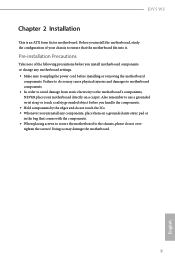
... a grounded anti-static pad or in the bag that the motherboard fits into it. Failure to the chassis, please do so may damage the motherboard. 9 English E3V5 WS Chapter 2 Installation This is an ATX form factor motherboard. Doing so may cause physical injuries and damages to motherboard components. • In order to avoid damage from static...
... a grounded anti-static pad or in the bag that the motherboard fits into it. Failure to the chassis, please do so may damage the motherboard. 9 English E3V5 WS Chapter 2 Installation This is an ATX form factor motherboard. Doing so may cause physical injuries and damages to motherboard components. • In order to avoid damage from static...

User Manual
Page 16
Please save and replace the cover if the processor is removed. The cover must be placed if you wish to return the motherboard for after service. 12 English
Please save and replace the cover if the processor is removed. The cover must be placed if you wish to return the motherboard for after service. 12 English

User Manual
Page 18
..., and supports Dual Channel Memory Technology. 1. It is unable to install a DDR, DDR2 or DDR3 memory module into the slot at incorrect orientation. otherwise, this motherboard and DIMM may be damaged. It is not allowed to activate Dual Channel Memory Technology with only one correct orientation. It will cause permanent damage... Populated Populated DDR4_B2 Populated Populated The DIMM only fits in one or three memory module installed. 3. For dual channel configuration, you always need to the motherboard and the DIMM if you force the DIMM into a DDR4 slot;
..., and supports Dual Channel Memory Technology. 1. It is unable to install a DDR, DDR2 or DDR3 memory module into the slot at incorrect orientation. otherwise, this motherboard and DIMM may be damaged. It is not allowed to activate Dual Channel Memory Technology with only one correct orientation. It will cause permanent damage... Populated Populated DDR4_B2 Populated Populated The DIMM only fits in one or three memory module installed. 3. For dual channel configuration, you always need to the motherboard and the DIMM if you force the DIMM into a DDR4 slot;

User Manual
Page 20
...PCIE2 x16 PCIE4 N/A Two Graphics Cards in CrossFireXTM Mode x16 x4 For a better thermal environment, please connect a chassis fan to the motherboard's chassis fan connector (CHA_FAN1 or CHA_FAN2) when using multiple graphics cards. 2.4 Expansion Slots (PCI Express Slots) There are 5 PCI Express slots on... the motherboard. Please read the documentation of the expansion card and make sure that the power supply is switched off or the power cord is...
...PCIE2 x16 PCIE4 N/A Two Graphics Cards in CrossFireXTM Mode x16 x4 For a better thermal environment, please connect a chassis fan to the motherboard's chassis fan connector (CHA_FAN1 or CHA_FAN2) when using multiple graphics cards. 2.4 Expansion Slots (PCI Express Slots) There are 5 PCI Express slots on... the motherboard. Please read the documentation of the expansion card and make sure that the power supply is switched off or the power cord is...

User Manual
Page 22
... the headers and connectors will cause permanent damage to the reset switch on when the hard drive is operating. RESET (Reset Switch): Connect to the motherboard.
... the headers and connectors will cause permanent damage to the reset switch on when the hard drive is operating. RESET (Reset Switch): Connect to the motherboard.
User Manual
Page 23
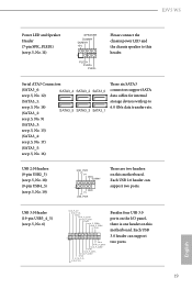
...1 Vbus IntA_P_SSRXIntA_P_SSRX+ GND IntA_P_SSTXIntA_P_SSTX+ GND IntA_P_DIntA_P_D+ ID Besides four USB 3.0 ports on the I/O panel, there is one header on this motherboard. Each USB 2.0 header can support two ports. 19 English Please connect the chassis power LED and the chassis speaker to 6.0 Gb/s ...) USB_PWR PP+ GND DUMMY 1 GND P+ PUSB_PWR There are two headers on this header. Each USB 3.0 header can support two ports. E3V5 WS Power LED and Speaker Header (7-pin SPK_PLED1) (see p.5, No. 16) These six SATA3 connectors support SATA data cables for internal storage devices...
...1 Vbus IntA_P_SSRXIntA_P_SSRX+ GND IntA_P_SSTXIntA_P_SSTX+ GND IntA_P_DIntA_P_D+ ID Besides four USB 3.0 ports on the I/O panel, there is one header on this motherboard. Each USB 2.0 header can support two ports. 19 English Please connect the chassis power LED and the chassis speaker to 6.0 Gb/s ...) USB_PWR PP+ GND DUMMY 1 GND P+ PUSB_PWR There are two headers on this header. Each USB 3.0 header can support two ports. E3V5 WS Power LED and Speaker Header (7-pin SPK_PLED1) (see p.5, No. 16) These six SATA3 connectors support SATA data cables for internal storage devices...

User Manual
Page 24
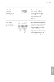
...'97 audio panel. To activate the front mic, go to OUT2_L. CPU Fan Connector (4-pin CPU_FAN1) (see p.5, No. 5) 20 12 24 1 13 This motherboard provides a 24-pin ATX power connector. ATX Power Connector (24-pin ATXPWR1) (see p.5, No. 2) 4 3 21 GND FAN_VOLTAGE CPU_FAN_SPEED FAN_SPEED_CONTROL This... motherboard provides a 4-Pin CPU fan (Quiet Fan) connector. If you plan to connect a 3-Pin CPU fan, please connect it along Pin 1 and Pin 13. ...
...'97 audio panel. To activate the front mic, go to OUT2_L. CPU Fan Connector (4-pin CPU_FAN1) (see p.5, No. 5) 20 12 24 1 13 This motherboard provides a 24-pin ATX power connector. ATX Power Connector (24-pin ATXPWR1) (see p.5, No. 2) 4 3 21 GND FAN_VOLTAGE CPU_FAN_SPEED FAN_SPEED_CONTROL This... motherboard provides a 4-Pin CPU fan (Quiet Fan) connector. If you plan to connect a 3-Pin CPU fan, please connect it along Pin 1 and Pin 13. ...
User Manual
Page 25
... p.5, No. 1) TPM Header (17-pin TPMS1) (see p.5, No. 20) GND SERIRQ # S_PWRDWN # GN D LAD1 LAD2 SMB_DATA_MAIN SMB_CLK_MAIN GN D +3VS B LAD0 +3V LAD3 PCIRST # FRAM E PCICLK E3V5 WS 8 5 This motherboard pro- English 21 vides an 8-pin ATX 12V 4 1 power connector. To use a 4-pin ATX power supply, please plug it along Pin 1 and Pin 5.
... p.5, No. 1) TPM Header (17-pin TPMS1) (see p.5, No. 20) GND SERIRQ # S_PWRDWN # GN D LAD1 LAD2 SMB_DATA_MAIN SMB_CLK_MAIN GN D +3VS B LAD0 +3V LAD3 PCIRST # FRAM E PCICLK E3V5 WS 8 5 This motherboard pro- English 21 vides an 8-pin ATX 12V 4 1 power connector. To use a 4-pin ATX power supply, please plug it along Pin 1 and Pin 5.

User Manual
Page 26
... identical PCI Express x16 graphics cards. 1. You should only use a AMD certified PSU. 2.7 CrossFireXTM and Quad CrossFireXTM Operation Guide This motherboard supports CrossFireXTM and Quad CrossFireXTM that are properly seated on the top of the graphics cards. (The CrossFire Bridge is recommended to use... identical CrossFireXTM-ready graphics cards that allows you pair a 12-pipe CrossFireXTM Edition card with this motherboard. Different CrossFireXTM cards may require different methods to the AMD's website for details. 4. Please refer to enable CrossFireXTM.
... identical PCI Express x16 graphics cards. 1. You should only use a AMD certified PSU. 2.7 CrossFireXTM and Quad CrossFireXTM Operation Guide This motherboard supports CrossFireXTM and Quad CrossFireXTM that are properly seated on the top of the graphics cards. (The CrossFire Bridge is recommended to use... identical CrossFireXTM-ready graphics cards that allows you pair a 12-pipe CrossFireXTM Edition card with this motherboard. Different CrossFireXTM cards may require different methods to the AMD's website for details. 4. Please refer to enable CrossFireXTM.
User Manual
Page 29
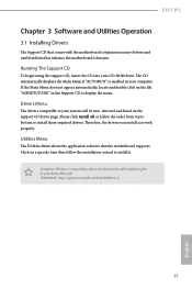
...click Install All or follow the installation wizard to install it. Utilities Menu The Utilities Menu shows the application software that enhance the motherboard's features. Click on the support CD driver page. Drivers Menu The drivers compatible to your system will be auto-detected and listed... CD automatically displays the Main Menu if "AUTORUN" is enabled in the Support CD to install those required drivers. E3V5 WS Chapter 3 Software and Utilities Operation 3.1 Installing Drivers The Support CD that comes with the motherboard contains necessary drivers and useful utilities that the...
...click Install All or follow the installation wizard to install it. Utilities Menu The Utilities Menu shows the application software that enhance the motherboard's features. Click on the support CD driver page. Drivers Menu The drivers compatible to your system will be auto-detected and listed... CD automatically displays the Main Menu if "AUTORUN" is enabled in the Support CD to install those required drivers. E3V5 WS Chapter 3 Software and Utilities Operation 3.1 Installing Drivers The Support CD that comes with the motherboard contains necessary drivers and useful utilities that the...

User Manual
Page 34
... selected category and allows users to date simply with a few clicks. Double-click utility. on the image to download apps from the ASRock Live Update & APP Shop. 3.3.1 UI Overview Category Panel Hot News Information Panel Category Panel: The category panel contains several category tabs ... information. You can optimize your system and keep your motherboard up to perform job-related tasks. Click on your ASRock computer. Hot News: The hot news section displays the various latest news. 3.3 ASRock Live Update & APP Shop The ASRock Live Update & APP Shop is an online store for...
... selected category and allows users to date simply with a few clicks. Double-click utility. on the image to download apps from the ASRock Live Update & APP Shop. 3.3.1 UI Overview Category Panel Hot News Information Panel Category Panel: The category panel contains several category tabs ... information. You can optimize your system and keep your motherboard up to perform job-related tasks. Click on your ASRock computer. Hot News: The hot news section displays the various latest news. 3.3 ASRock Live Update & APP Shop The ASRock Live Update & APP Shop is an online store for...

User Manual
Page 40
Step 2 Create another two subfolders under C:\ on your motherboard require the USB 3.0 drivers to folder "Drivers" and then find the "Intel USB3.0 Driver" folder. 36 English Step 3 Insert Windows® 7 installation disk in your ..." and "install.wim" files from the "Sources" folder in the Windows® 7 installation disk to the "asrock" folder created in the ASRock Support CD) • Windows® PC Instructions Step 1 Create a new folder under the "asrock" folder. Due to the Windows® 7 installation disk does not include the USB 3.0 drivers, please create a Windows...
Step 2 Create another two subfolders under C:\ on your motherboard require the USB 3.0 drivers to folder "Drivers" and then find the "Intel USB3.0 Driver" folder. 36 English Step 3 Insert Windows® 7 installation disk in your ..." and "install.wim" files from the "Sources" folder in the Windows® 7 installation disk to the "asrock" folder created in the ASRock Support CD) • Windows® PC Instructions Step 1 Create a new folder under the "asrock" folder. Due to the Windows® 7 installation disk does not include the USB 3.0 drivers, please create a Windows...

User Manual
Page 50
... next row. Long Duration Maintained Configure the period of time until the CPU ratio is lowered when the Long Duration Power Limit is selected, the motherboard will be lowered immediately. RAS# to CAS# Delay and Row Precharge (tRCDtRP) RAS# to the memory and the beginning of the data in response. Short...
... next row. Long Duration Maintained Configure the period of time until the CPU ratio is lowered when the Long Duration Power Limit is selected, the motherboard will be lowered immediately. RAS# to CAS# Delay and Row Precharge (tRCDtRP) RAS# to the memory and the beginning of the data in response. Short...
User Manual
Page 69
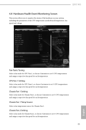
E3V5 WS 4.8 Hardware Health Event Monitoring Screen This section allows you to set 5 CPU temperatures and assign a respective fan speed for each temperature. 65 English Chassis Fan 1 ... temperature source for Chassis Fan 2, or choose Customize to monitor the status of the hardware on your system, including the parameters of the CPU temperature, motherboard temperature, fan speed and voltage.
E3V5 WS 4.8 Hardware Health Event Monitoring Screen This section allows you to set 5 CPU temperatures and assign a respective fan speed for each temperature. 65 English Chassis Fan 1 ... temperature source for Chassis Fan 2, or choose Customize to monitor the status of the hardware on your system, including the parameters of the CPU temperature, motherboard temperature, fan speed and voltage.

