

User Manual
Page 3
... 1 1.2 Specifications 2 1.3 Motherboard Layout 5 1.4 I/O Panel 7 Chapter 2 Installation 9 2.1 Installing the CPU 10 2.2 Installing the CPU Fan and Heatsink 13 2.3 Installing Memory Modules (DIMM) 14 2.4 Expansion Slots (PCI Express Slots) 16 2.5 Jumpers Setup 17 2.6 Onboard Headers and Connectors 18 2.7 CrossFireXTM and Quad CrossFireXTM Operation Guide 22 2.7.1 Installing Two CrossFireXTM-Ready Graphics Cards 22 2.7.2 Driver Installation and Setup 24 Chapter 3 Software and Utilities Operation 25 3.1 Installing Drivers 25 3.2 A-Tuning 26 3.3 ASRock Live Update...
... 1 1.2 Specifications 2 1.3 Motherboard Layout 5 1.4 I/O Panel 7 Chapter 2 Installation 9 2.1 Installing the CPU 10 2.2 Installing the CPU Fan and Heatsink 13 2.3 Installing Memory Modules (DIMM) 14 2.4 Expansion Slots (PCI Express Slots) 16 2.5 Jumpers Setup 17 2.6 Onboard Headers and Connectors 18 2.7 CrossFireXTM and Quad CrossFireXTM Operation Guide 22 2.7.1 Installing Two CrossFireXTM-Ready Graphics Cards 22 2.7.2 Driver Installation and Setup 24 Chapter 3 Software and Utilities Operation 25 3.1 Installing Drivers 25 3.2 A-Tuning 26 3.3 ASRock Live Update...

User Manual
Page 4
... 3.4 Creating Windows® 7 Installation Disk with USB 3.0 Drivers Packed 36 Chapter 4 UEFI SETUP UTILITY 40 4.1 Introduction 40 4.2 EZ Mode 41 4.3 Advanced Mode 42 4.3.1 UEFI Menu Bar 42 4.3.2 Navigation Keys 43 4.4 Main Screen 44 4.5 OC Tweaker Screen 45 4.6 Advanced Screen 53 4.6.1 CPU Configuration 54 4.6.2 Chipset Configuration 56 4.6.3 Storage Configuration 58 4.6.4 ACPI Configuration 59 4.6.5 USB Configuration 60 4.6.6 Trusted Computing 61 4.7 Tools 62 4.8 Hardware Health Event Monitoring Screen 65 4.9 Security Screen 67 4.10 Boot Screen 68...
... 3.4 Creating Windows® 7 Installation Disk with USB 3.0 Drivers Packed 36 Chapter 4 UEFI SETUP UTILITY 40 4.1 Introduction 40 4.2 EZ Mode 41 4.3 Advanced Mode 42 4.3.1 UEFI Menu Bar 42 4.3.2 Navigation Keys 43 4.4 Main Screen 44 4.5 OC Tweaker Screen 45 4.6 Advanced Screen 53 4.6.1 CPU Configuration 54 4.6.2 Chipset Configuration 56 4.6.3 Storage Configuration 58 4.6.4 ACPI Configuration 59 4.6.5 USB Configuration 60 4.6.6 Trusted Computing 61 4.7 Tools 62 4.8 Hardware Health Event Monitoring Screen 65 4.9 Security Screen 67 4.10 Boot Screen 68...
User Manual
Page 5
... quality control. Chapter 3 contains the operation guide of the BIOS setup. Chapter 4 contains the configuration guide of the software and utilities. If you for specific information about the model you are using. You may find the latest VGA cards and CPU support list on ASRock's website without notice. ASRock website http://www.asrock.com. 1.1 Package Contents • ASRock E3V5 WS Motherboard (ATX Form Factor) • ASRock E3V5 WS Quick Installation Guide • ASRock E3V5 WS Support CD • 2 x Serial ATA (SATA) Data Cables (Optional) • 1 x I/O Panel Shield...
... quality control. Chapter 3 contains the operation guide of the BIOS setup. Chapter 4 contains the configuration guide of the software and utilities. If you for specific information about the model you are using. You may find the latest VGA cards and CPU support list on ASRock's website without notice. ASRock website http://www.asrock.com. 1.1 Package Contents • ASRock E3V5 WS Motherboard (ATX Form Factor) • ASRock E3V5 WS Quick Installation Guide • ASRock E3V5 WS Support CD • 2 x Serial ATA (SATA) Data Cables (Optional) • 1 x I/O Panel Shield...

User Manual
Page 6
...μ Gold Contact in DIMM Slots Expansion Slot • 2 x PCI Express 3.0 x16 Slots (PCIE2: x16 mode; With Intel® CoreTM i7/i5 CPU, ECC function is required to use an HD front panel audio module and enable the multi-channel audio feature through the audio driver. • Premium Blu-ray Audio support • Supports Surge Protection (ASRock Full Spike Protection) • ELNA Audio Caps 2 1.2 Specifications Platform CPU • ATX Form Factor • Solid...
...μ Gold Contact in DIMM Slots Expansion Slot • 2 x PCI Express 3.0 x16 Slots (PCIE2: x16 mode; With Intel® CoreTM i7/i5 CPU, ECC function is required to use an HD front panel audio module and enable the multi-channel audio feature through the audio driver. • Premium Blu-ray Audio support • Supports Surge Protection (ASRock Full Spike Protection) • ELNA Audio Caps 2 1.2 Specifications Platform CPU • ATX Form Factor • Solid...
User Manual
Page 7
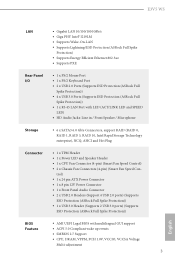
... 2 USB 3.0 ports) (Supports ESD Protection (ASRock Full Spike Protection)) BIOS Feature • AMI UEFI Legal BIOS with LED (ACT/LINK LED and SPEED LED) • HD Audio Jacks: Line in / Front Speaker / Microphone Storage • 6 x SATA3 6.0 Gb/s Connectors, support RAID (RAID 0, RAID 1, RAID 5, RAID 10, Intel Rapid Storage Technology enterprise), NCQ, AHCI and Hot Plug Connector • 1 x TPM Header • 1 x Power LED and Speaker Header • 1 x CPU Fan Connector (4-pin) (Smart Fan Speed Control) • 2 x Chassis Fan Connectors (4-pin) (Smart Fan Speed Con- E3V5 WS LAN...
... 2 USB 3.0 ports) (Supports ESD Protection (ASRock Full Spike Protection)) BIOS Feature • AMI UEFI Legal BIOS with LED (ACT/LINK LED and SPEED LED) • HD Audio Jacks: Line in / Front Speaker / Microphone Storage • 6 x SATA3 6.0 Gb/s Connectors, support RAID (RAID 0, RAID 1, RAID 5, RAID 10, Intel Rapid Storage Technology enterprise), NCQ, AHCI and Hot Plug Connector • 1 x TPM Header • 1 x Power LED and Speaker Header • 1 x CPU Fan Connector (4-pin) (Smart Fan Speed Control) • 2 x Chassis Fan Connectors (4-pin) (Smart Fan Speed Con- E3V5 WS LAN...

User Manual
Page 8
... setting in the BIOS, applying Untied Overclocking Technology, or using third-party overclocking tools. Overclocking may affect your system's stability, or even cause damage to page 36 for more detailed instructions. * For the updated Windows® 10 driver, please visit ASRock's website for possible damage caused by CPU temperature) • CPU/Chassis Fan multi-speed control • Voltage monitoring: +12V, +5V, +3.3V, CPU Vcore OS • Microsoft® Windows® 10 64-bit / 8.1 64-bit...
... setting in the BIOS, applying Untied Overclocking Technology, or using third-party overclocking tools. Overclocking may affect your system's stability, or even cause damage to page 36 for more detailed instructions. * For the updated Windows® 10 driver, please visit ASRock's website for possible damage caused by CPU temperature) • CPU/Chassis Fan multi-speed control • Voltage monitoring: +12V, +5V, +3.3V, CPU Vcore OS • Microsoft® Windows® 10 64-bit / 8.1 64-bit...

User Manual
Page 10
...1 ATX 12V Power Connector (ATX12V1) 2 CPU Fan Connector (CPU_FAN1) 3 2 x 288-pin DDR4 DIMM Slots (DDR4_A1, DDR4_B1) 4 2 x 288-pin DDR4 DIMM Slots (DDR4_A2, DDR4_B2) 5 ATX Power Connector (ATXPWR1) 6 USB 3.0 Header (USB3_4_5) 7 Chassis Fan Connector (CHA_FAN1) 8 Clear CMOS Jumper (CLRMOS1) 9 SATA3 Connector (SATA3_2) 10 Chassis Fan Connector (CHA_FAN2) 11 Power LED and Speaker Header (SPK_PLED1) 12 SATA3 Connector (SATA3_0) 13 System Panel Header (PANEL1) 14 SATA3 Connector (SATA3_1) 15 SATA3 Connector (SATA3_3) 16 SATA3 Connector (SATA3_5) 17 SATA3 Connector (SATA3_4) 18 USB 2.0 Header (USB2_3...
...1 ATX 12V Power Connector (ATX12V1) 2 CPU Fan Connector (CPU_FAN1) 3 2 x 288-pin DDR4 DIMM Slots (DDR4_A1, DDR4_B1) 4 2 x 288-pin DDR4 DIMM Slots (DDR4_A2, DDR4_B2) 5 ATX Power Connector (ATXPWR1) 6 USB 3.0 Header (USB3_4_5) 7 Chassis Fan Connector (CHA_FAN1) 8 Clear CMOS Jumper (CLRMOS1) 9 SATA3 Connector (SATA3_2) 10 Chassis Fan Connector (CHA_FAN2) 11 Power LED and Speaker Header (SPK_PLED1) 12 SATA3 Connector (SATA3_0) 13 System Panel Header (PANEL1) 14 SATA3 Connector (SATA3_1) 15 SATA3 Connector (SATA3_3) 16 SATA3 Connector (SATA3_5) 17 SATA3 Connector (SATA3_4) 18 USB 2.0 Header (USB2_3...

User Manual
Page 20
... Mode x16 x4 For a better thermal environment, please connect a chassis fan to the motherboard's chassis fan connector (CHA_FAN1 or CHA_FAN2) when using multiple graphics cards. English 16 PCIE4 (PCIe 3.0 x16 slot) is used for PCI Express x1 lane width cards. PCIe slots: PCIE1 (PCIe 3.0 x1 slot) is used for PCI Express x4 lane width graphics cards. PCIE5 (PCIe 3.0 x1 slot) is unplugged. 2.4 Expansion Slots (PCI Express Slots) There are 5 PCI Express slots on the motherboard. Before installing an expansion card, please make necessary hardware settings for PCI Express...
... Mode x16 x4 For a better thermal environment, please connect a chassis fan to the motherboard's chassis fan connector (CHA_FAN1 or CHA_FAN2) when using multiple graphics cards. English 16 PCIE4 (PCIe 3.0 x16 slot) is used for PCI Express x1 lane width cards. PCIe slots: PCIE1 (PCIe 3.0 x1 slot) is used for PCI Express x4 lane width graphics cards. PCIE5 (PCIe 3.0 x1 slot) is unplugged. 2.4 Expansion Slots (PCI Express Slots) There are 5 PCI Express slots on the motherboard. Before installing an expansion card, please make necessary hardware settings for PCI Express...

User Manual
Page 21
E3V5 WS 2.5 Jumpers Setup The illustration shows how jumpers are "Short" when a jumper cap is placed on these 2 pins. Clear CMOS Jumper (CLRMOS1) (see p.5, No. 8) Default Clear CMOS CLRMOS1 allows you update the BIOS. However, please do the clear-CMOS action. Please be noted that the password, date, time, and user default profile will be cleared only if the CMOS battery is "Open". If no jumper cap is placed on the pins, the jumper is "Short". When the jumper cap...
E3V5 WS 2.5 Jumpers Setup The illustration shows how jumpers are "Short" when a jumper cap is placed on these 2 pins. Clear CMOS Jumper (CLRMOS1) (see p.5, No. 8) Default Clear CMOS CLRMOS1 allows you update the BIOS. However, please do the clear-CMOS action. Please be noted that the password, date, time, and user default profile will be cleared only if the CMOS battery is "Open". If no jumper cap is placed on the pins, the jumper is "Short". When the jumper cap...

User Manual
Page 22
... the chassis front panel. The front panel design may configure the way to turn off (S5). A front panel module mainly consists of power switch, reset switch, power LED, hard drive activity LED, speaker and etc. Note the positive and negative pins before connecting the cables. PWRBTN (Power Switch): Connect to perform a normal restart. The LED is on when the system is reading or writing data. English 18 2.6 Onboard Headers and Connectors Onboard headers and connectors are matched correctly. Press the reset switch...
... the chassis front panel. The front panel design may configure the way to turn off (S5). A front panel module mainly consists of power switch, reset switch, power LED, hard drive activity LED, speaker and etc. Note the positive and negative pins before connecting the cables. PWRBTN (Power Switch): Connect to perform a normal restart. The LED is on when the system is reading or writing data. English 18 2.6 Onboard Headers and Connectors Onboard headers and connectors are matched correctly. Press the reset switch...
User Manual
Page 23
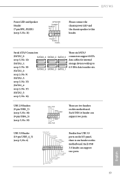
...+ IntA_P_SSTXGND IntA_P_SSRX+ IntA_P_SSRXVbus 1 Vbus IntA_P_SSRXIntA_P_SSRX+ GND IntA_P_SSTXIntA_P_SSTX+ GND IntA_P_DIntA_P_D+ ID Besides four USB 3.0 ports on the I/O panel, there is one header on this motherboard. Each USB 2.0 header can support two ports. 19 English E3V5 WS Power LED and Speaker Header (7-pin SPK_PLED1) (see p.5, No. 16) These six SATA3 connectors support SATA data cables for internal storage devices with up to this header. Serial ATA3 Connectors (SATA3_0: see p.5, No. 12) SATA3_4 SATA3_2 SATA3_0 (SATA3_1: see p.5, No. 14...
...+ IntA_P_SSTXGND IntA_P_SSRX+ IntA_P_SSRXVbus 1 Vbus IntA_P_SSRXIntA_P_SSRX+ GND IntA_P_SSTXIntA_P_SSTX+ GND IntA_P_DIntA_P_D+ ID Besides four USB 3.0 ports on the I/O panel, there is one header on this motherboard. Each USB 2.0 header can support two ports. 19 English E3V5 WS Power LED and Speaker Header (7-pin SPK_PLED1) (see p.5, No. 16) These six SATA3 connectors support SATA data cables for internal storage devices with up to this header. Serial ATA3 Connectors (SATA3_0: see p.5, No. 12) SATA3_4 SATA3_2 SATA3_0 (SATA3_1: see p.5, No. 14...

User Manual
Page 24
... connecting audio devices to MIC2_L. You don't need to OUT2_L. Chassis Fan Connectors (4-pin CHA_FAN1) (see p.5, No. 7) (4-pin CHA_FAN2) (see p.5, No. 5) 20 12 24 1 13 This motherboard provides a 24-pin ATX power connector. ATX Power Connector (24-pin ATXPWR1) (see p.5, No. 10) GND FAN_VOLTAGE CHA_FAN_SPEED FAN_SPEED_CONTROL Please connect fan cables to the fan connectors and match the black wire to the ground pin. Connect Ground (GND) to function correctly. If you use a 20-pin ATX power supply, please plug it to install...
... connecting audio devices to MIC2_L. You don't need to OUT2_L. Chassis Fan Connectors (4-pin CHA_FAN1) (see p.5, No. 7) (4-pin CHA_FAN2) (see p.5, No. 5) 20 12 24 1 13 This motherboard provides a 24-pin ATX power connector. ATX Power Connector (24-pin ATXPWR1) (see p.5, No. 10) GND FAN_VOLTAGE CHA_FAN_SPEED FAN_SPEED_CONTROL Please connect fan cables to the fan connectors and match the black wire to the ground pin. Connect Ground (GND) to function correctly. If you use a 20-pin ATX power supply, please plug it to install...

User Manual
Page 26
... refer to your graphics card driver supports AMD CrossFireXTM technology. If you pair a 12-pipe CrossFireXTM Edition card with this motherboard. Make sure that your graphics card vendor for detailed installation guide. 2.7.1 Installing Two CrossFireXTM-Ready Graphics Cards Step 1 Insert one graphics card into PCIE2 slot and the other graphics card to three identical PCI Express x16 graphics cards. 1. Please refer to enable CrossFireXTM. Make sure that the cards are AMD certified. 2. Please refer to AMD graphics card manuals for details...
... refer to your graphics card driver supports AMD CrossFireXTM technology. If you pair a 12-pipe CrossFireXTM Edition card with this motherboard. Make sure that your graphics card vendor for detailed installation guide. 2.7.1 Installing Two CrossFireXTM-Ready Graphics Cards Step 1 Insert one graphics card into PCIE2 slot and the other graphics card to three identical PCI Express x16 graphics cards. 1. Please refer to enable CrossFireXTM. Make sure that the cards are AMD certified. 2. Please refer to AMD graphics card manuals for details...
User Manual
Page 29
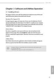
... provided by Microsoft. Drivers Menu The drivers compatible to your system will be auto-detected and listed on the file "ASRSETUP.EXE" in your CD-ROM drive. E3V5 WS Chapter 3 Software and Utilities Operation 3.1 Installing Drivers The Support CD that comes with the motherboard contains necessary drivers and useful utilities that the motherboard supports. Running The Support CD To begin using the support CD, insert the CD into your computer. Click on a specific item then follow...
... provided by Microsoft. Drivers Menu The drivers compatible to your system will be auto-detected and listed on the file "ASRSETUP.EXE" in your CD-ROM drive. E3V5 WS Chapter 3 Software and Utilities Operation 3.1 Installing Drivers The Support CD that comes with the motherboard contains necessary drivers and useful utilities that the motherboard supports. Running The Support CD To begin using the support CD, insert the CD into your computer. Click on a specific item then follow...

User Manual
Page 40
... Windows® 7 Installation Disk with the Intel® USB 3.0 eXtensible Host Controller (xHCI) drivers packed into the ISO file of your motherboard require the USB 3.0 drivers to function properly. Requirements • A program that can create and modify ISO files, such as UltraISO • Windows® 7 installation disk • USB 3.0 drivers (included in Step 1. Step 6 Go to the "asrock" folder created in the ASRock Support CD) • Windows® PC Instructions Step...
... Windows® 7 Installation Disk with the Intel® USB 3.0 eXtensible Host Controller (xHCI) drivers packed into the ISO file of your motherboard require the USB 3.0 drivers to function properly. Requirements • A program that can create and modify ISO files, such as UltraISO • Windows® 7 installation disk • USB 3.0 drivers (included in Step 1. Step 6 Go to the "asrock" folder created in the ASRock Support CD) • Windows® PC Instructions Step...

User Manual
Page 61
... the power state after a power failure. If [Power On] is selected, the system will be switched off when the power recovers. Good Night LED By enabling Good Night LED, the Power/HDD LEDs will start to enable onboard HD audio and automatically disable it when a sound card is installed. Set to Auto to boot up when the power recovers. Onboard HD Audio Enable/disable onboard HD audio. Deep Sleep Configure deep sleep mode for all PCH DMI devices. E3V5 WS PCH DMI ASPM Support This option enables/disables the ASPM support for power...
... the power state after a power failure. If [Power On] is selected, the system will be switched off when the power recovers. Good Night LED By enabling Good Night LED, the Power/HDD LEDs will start to enable onboard HD audio and automatically disable it when a sound card is installed. Set to Auto to boot up when the power recovers. Onboard HD Audio Enable/disable onboard HD audio. Deep Sleep Configure deep sleep mode for all PCH DMI devices. E3V5 WS PCH DMI ASPM Support This option enables/disables the ASPM support for power...

User Manual
Page 66
... internet access at specified times via OMG. Easy Driver Installer For users that don't have an optical disk drive to other users. OMG (Online Management Guard) Administrators are having trouble with your current PC and the devices connected. Please setup network configuration before using UEFI Tech Service. Easy RAID Installer Easy RAID Installer helps you are able to your USB storage device. UEFI Tech Service Contact ASRock Tech Service if you to copy the RAID driver from our support 62...
... internet access at specified times via OMG. Easy Driver Installer For users that don't have an optical disk drive to other users. OMG (Online Management Guard) Administrators are having trouble with your current PC and the devices connected. Please setup network configuration before using UEFI Tech Service. Easy RAID Installer Easy RAID Installer helps you are able to your USB storage device. UEFI Tech Service Contact ASRock Tech Service if you to copy the RAID driver from our support 62...
User Manual
Page 67
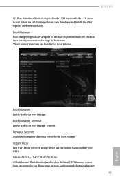
... Flash Save UEFI files in the UEFI that installs the LAN driver to your UEFI. E3V5 WS CD, Easy Driver Installer is specifically designed for the dual OS platform/multi-OS platform users to easily customize and manage the boot menu. *Please connect more than one boot devices to use this tool. DHCP (Auto IP), Auto ASRock Internet Flash downloads and updates the latest UEFI firmware version from our servers for the Boot Manager. Boot Manager Boot Manager is a handy tool in your USB storage device...
... Flash Save UEFI files in the UEFI that installs the LAN driver to your UEFI. E3V5 WS CD, Easy Driver Installer is specifically designed for the dual OS platform/multi-OS platform users to easily customize and manage the boot menu. *Please connect more than one boot devices to use this tool. DHCP (Auto IP), Auto ASRock Internet Flash downloads and updates the latest UEFI firmware version from our servers for the Boot Manager. Boot Manager Boot Manager is a handy tool in your USB storage device...

User Manual
Page 68
Internet Setting Enable or disable sound effects in your USB pen drive before using this to plug in the setup utility. Network Configuration Use this function. Flash. *For BIOS backup and recovery purpose, it is recommended to configure internet connection settings for Internet Flash. UEFI Download Server Select a server to download the UEFI firmware. 64 English
Internet Setting Enable or disable sound effects in your USB pen drive before using this to plug in the setup utility. Network Configuration Use this function. Flash. *For BIOS backup and recovery purpose, it is recommended to configure internet connection settings for Internet Flash. UEFI Download Server Select a server to download the UEFI firmware. 64 English

User Manual
Page 71
... enter to change the settings in the UEFI Setup Utility. Only the administrator has authority to use discrete TPM Module. 67 English Supervisor Password Set or change the supervisor/user password for the administrator account. E3V5 WS 4.9 Security Screen In this section you may also clear the user password. You may set or change the password for the system. User Password Set or change the password for Windows 8.1 Secure Boot. Intel(R) Platform Trust Technology Enable/disable Intel PTT in the UEFI Setup Utility. Disable this option...
... enter to change the settings in the UEFI Setup Utility. Only the administrator has authority to use discrete TPM Module. 67 English Supervisor Password Set or change the supervisor/user password for the administrator account. E3V5 WS 4.9 Security Screen In this section you may also clear the user password. You may set or change the password for the system. User Password Set or change the password for Windows 8.1 Secure Boot. Intel(R) Platform Trust Technology Enable/disable Intel PTT in the UEFI Setup Utility. Disable this option...


