
User Manual
Page 3
... Liquid has been spilled into the system. • The system does not function properly even if you follow all power, modem, and network cables from the power outlets before you leave plenty of attempting to ensure your system. If you read the following technical problems with the product... service technician or your system. Setting up the system on your retailer. • The power cord or plug is turned OFF, a small amount of safety for ventilation. Openings on the power cord or allow anything to meet the latest standards of electrical current still flows. However, ...
... Liquid has been spilled into the system. • The system does not function properly even if you follow all power, modem, and network cables from the power outlets before you leave plenty of attempting to ensure your system. If you read the following technical problems with the product... service technician or your system. Setting up the system on your retailer. • The power cord or plug is turned OFF, a small amount of safety for ventilation. Openings on the power cord or allow anything to meet the latest standards of electrical current still flows. However, ...

User Manual
Page 7
... One AC Power Cord One AC/DC Adapter One HDMI to quality and endurance. You may find the latest VGA cards and CPU support lists on ASRock website without notice. It delivers excellent performance with robust design conforming to ASRock's commitment to DVI Adapter One Anti-Slip Pad Remote Controller (Core 100HT / Core 100HT-BD) SATA and Power Cables 7
... One AC Power Cord One AC/DC Adapter One HDMI to quality and endurance. You may find the latest VGA cards and CPU support lists on ASRock website without notice. It delivers excellent performance with robust design conforming to ASRock's commitment to DVI Adapter One Anti-Slip Pad Remote Controller (Core 100HT / Core 100HT-BD) SATA and Power Cables 7

User Manual
Page 8
... is a certain risk involved with THX TruStudio ProTM Gigabit LAN 802.11b/g/n wireless LAN (Core 100HT / Core 100HT-BD) Support MCE function (Core 100HT / Core 100HT-BD) 90W/19V Adapter 195mm(W)x70mm(H)x186m(L) 2.5L For barebone system, it may affect your ... Core 100HT) BD Combo*2 (Core 100HT-BD) 2 x USB3.0, 1 x Microphone, 1 x Earphone 1 x HDMI, 1 x D-Sub VGA, 6 x USB2.0, 1 x S/PDIF, 1 x eSATAII*3 7.0 Ch HD Audio with overclocking, including adjusting the setting in AHCI mode only. Processor Chipset Memory VGA HDD DVD Front I/O Rear I/O Sound LAN WiFi Remote Controller Power Dimension...
... is a certain risk involved with THX TruStudio ProTM Gigabit LAN 802.11b/g/n wireless LAN (Core 100HT / Core 100HT-BD) Support MCE function (Core 100HT / Core 100HT-BD) 90W/19V Adapter 195mm(W)x70mm(H)x186m(L) 2.5L For barebone system, it may affect your ... Core 100HT) BD Combo*2 (Core 100HT-BD) 2 x USB3.0, 1 x Microphone, 1 x Earphone 1 x HDMI, 1 x D-Sub VGA, 6 x USB2.0, 1 x S/PDIF, 1 x eSATAII*3 7.0 Ch HD Audio with overclocking, including adjusting the setting in AHCI mode only. Processor Chipset Memory VGA HDD DVD Front I/O Rear I/O Sound LAN WiFi Remote Controller Power Dimension...
User Manual
Page 9
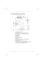
Infrared module header 8. CPU socket 9. Fan connector 5. Memory socket 6. SATA connector: For ODD SATA data cable 12. ATX5V output power connector for slim ODD & 2.5" HDD 13. SATA connector: For second HDD SATA data cable 4. Clear CMOS jumper 11. Fan connector 7. Northbridge heatsink 2. 1.3 System Motherboard Components HM55-HT Design in Taipei PCIE1 1. J1 jumper: For second HDD SATA power cable 3. Mini-PCI Express expansion slot: For WiFi module 10. SATA connector: For HDD SATA data cable EuP Ready RoHS DDR3_A1FSB800 DDR3_B1 9
Infrared module header 8. CPU socket 9. Fan connector 5. Memory socket 6. SATA connector: For ODD SATA data cable 12. ATX5V output power connector for slim ODD & 2.5" HDD 13. SATA connector: For second HDD SATA data cable 4. Clear CMOS jumper 11. Fan connector 7. Northbridge heatsink 2. 1.3 System Motherboard Components HM55-HT Design in Taipei PCIE1 1. J1 jumper: For second HDD SATA power cable 3. Mini-PCI Express expansion slot: For WiFi module 10. SATA connector: For HDD SATA data cable EuP Ready RoHS DDR3_A1FSB800 DDR3_B1 9
User Manual
Page 10
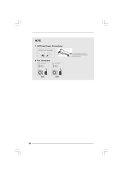
SATA and Power Connections Connect to ODD SATA & Power Connections HDD ODD Connect to HDD Connect to SATA Connector (11) Connect to ATX5V Power Connector (12) Connect to SATA Connector (13) 2. NOTE. 1. Fan Connection Fan connector Ground +12V Rotation Fan connector Ground +5V Rotation item 4 item 6 10
SATA and Power Connections Connect to ODD SATA & Power Connections HDD ODD Connect to HDD Connect to SATA Connector (11) Connect to ATX5V Power Connector (12) Connect to SATA Connector (13) 2. NOTE. 1. Fan Connection Fan connector Ground +12V Rotation Fan connector Ground +5V Rotation item 4 item 6 10
User Manual
Page 12
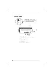
Microphone 31. Remove the screws on the backside. 2. Slide the top panel backwards. eSATAII HDMI 26 27 31 30 29 28 26. Power ON/OFF button with status indicator 28. USB3.0 ports: USB devices 12 Earphone 30. Drive activity indicator 29. Optical Disc Drive 27. 1.5 System Chassis Opening the system chassis 1.
Microphone 31. Remove the screws on the backside. 2. Slide the top panel backwards. eSATAII HDMI 26 27 31 30 29 28 26. Power ON/OFF button with status indicator 28. USB3.0 ports: USB devices 12 Earphone 30. Drive activity indicator 29. Optical Disc Drive 27. 1.5 System Chassis Opening the system chassis 1.
User Manual
Page 16
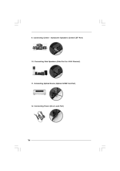
Connecting Side Speakers (Side Port for 4/6/8 Channel) 11. Connecting Power (DC-In Jack Port) 16 9. Connecting Optical Device (Optical S/PDIF Out Port) 12. Connecting Center / Subwoofer Speakers (Center/LEF Port) 10.
Connecting Side Speakers (Side Port for 4/6/8 Channel) 11. Connecting Power (DC-In Jack Port) 16 9. Connecting Optical Device (Optical S/PDIF Out Port) 12. Connecting Center / Subwoofer Speakers (Center/LEF Port) 10.
User Manual
Page 17
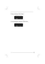
Connecting Earphone / Microphone / USB3.0 Devices 17 Power on the System (Power Switch) 14. 13.
Connecting Earphone / Microphone / USB3.0 Devices 17 Power on the System (Power Switch) 14. 13.
User Manual
Page 18
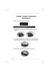
To change the storage drives, you need to remove SATA and power cables from ODD / HDD first, and unscrew the screws from the bay. 18 Chapter 3 System Components Reinstallation 1. Slide the side cover toward the rear panel and pull the side cover upwards. 3. Remove the cover screws on the rear panel. Note: For safety reasons, please ensure that the power cord is disconnected before opening the case. 2. Pull ODD / HDD rack backwards and take it out from both side. 4.
To change the storage drives, you need to remove SATA and power cables from ODD / HDD first, and unscrew the screws from the bay. 18 Chapter 3 System Components Reinstallation 1. Slide the side cover toward the rear panel and pull the side cover upwards. 3. Remove the cover screws on the rear panel. Note: For safety reasons, please ensure that the power cord is disconnected before opening the case. 2. Pull ODD / HDD rack backwards and take it out from both side. 4.

User Manual
Page 21
Connect the other end to the top HDD. 7. Connect the other SATA and power cables to the bottom HDD. 5. Connect one end of SATA and power cables to the ODD and the other end to SATAII_3 and J1 connectors on the motherboard. 6. Replace the side cover and fasten the screws. 21 4.
Connect the other end to the top HDD. 7. Connect the other SATA and power cables to the bottom HDD. 5. Connect one end of SATA and power cables to the ODD and the other end to SATAII_3 and J1 connectors on the motherboard. 6. Replace the side cover and fasten the screws. 21 4.
User Manual
Page 23
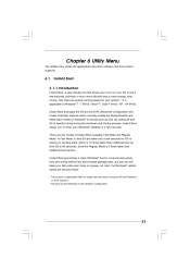
...) features which is applicable ONLY to single user that allows you can still keep your data safe even there is a power cut. Also, the Windows® update speed will become faster. * This function is 10 times faster than traditional boot up time. Chapter 6 Utility Menu The ... up time. There are two modes of Instant Boot available: Fast Mode and Regular Mode. Instant Boot guarantees a clean Windows® boot to consume less power, time and money without any accumulated garbage data, and you to enter your system *. By calling S3 and S4 at specific timing during the shutdown...
...) features which is applicable ONLY to single user that allows you can still keep your data safe even there is a power cut. Also, the Windows® update speed will become faster. * This function is 10 times faster than traditional boot up time. Chapter 6 Utility Menu The ... up time. There are two modes of Instant Boot available: Fast Mode and Regular Mode. Instant Boot guarantees a clean Windows® boot to consume less power, time and money without any accumulated garbage data, and you to enter your system *. By calling S3 and S4 at specific timing during the shutdown...

User Manual
Page 25
... Boot icon on the desktop, then Instant Boot main menu will find an ASRock Instant Boot icon on if you select "Fast Mode". On Instant Boot main menu, you want to shut down the computer, please simply select "Shut ...Down" from Windows® "Start menu". Please notice that , please click "Apply" to keep AC power on the Windows® desktop. e. After the installation is completed, you need to save the change. After that you will pop up. When you can...
... Boot icon on the desktop, then Instant Boot main menu will find an ASRock Instant Boot icon on if you select "Fast Mode". On Instant Boot main menu, you want to shut down the computer, please simply select "Shut ...Down" from Windows® "Start menu". Please notice that , please click "Apply" to keep AC power on the Windows® desktop. e. After the installation is completed, you need to save the change. After that you will pop up. When you can...
User Manual
Page 28
...system and enter Windows®, the system will start the OC Tuner. If you close OC Tuner window. There are three sections in ASRock OC Tuner main menu: System Health, Hardware Monitor, Overclocking and Voltage Control. 28 After the installation is recommended to run OC tuner,... risk and expense. C. D. Note: If system hangs after overclocking, please remove AC power cord and plug AC power cord again before you made. ASRock is running very stably. Double click ASRock OC Tuner icon on the desktop, then ASRock OC Tuner main menu will automatically start with the settings you...
...system and enter Windows®, the system will start the OC Tuner. If you close OC Tuner window. There are three sections in ASRock OC Tuner main menu: System Health, Hardware Monitor, Overclocking and Voltage Control. 28 After the installation is recommended to run OC tuner,... risk and expense. C. D. Note: If system hangs after overclocking, please remove AC power cord and plug AC power cord again before you made. ASRock is running very stably. Double click ASRock OC Tuner icon on the desktop, then ASRock OC Tuner main menu will automatically start with the settings you...

User Manual
Page 30
... a network. 30 PowerDVD World-renowned and award-winning PowerDVD delivers the ultimate DVD and high-definition movie experience on the PC. * The bundled PowerDVD is a powerful yet practical tool for details. 6.3 CyberLink D VD Suite free bundle (T rial version , DVD (Trial version, including PowerDVD, PowerDirector, etc) CyberLink DVD Suite includes five softwares...
... a network. 30 PowerDVD World-renowned and award-winning PowerDVD delivers the ultimate DVD and high-definition movie experience on the PC. * The bundled PowerDVD is a powerful yet practical tool for details. 6.3 CyberLink D VD Suite free bundle (T rial version , DVD (Trial version, including PowerDVD, PowerDirector, etc) CyberLink DVD Suite includes five softwares...

User Manual
Page 35
... Charge & Charge Anytime! With App Charger driver installed, you ¡V ASRock App Charger. ASRock App Charger allows you to quickly charge many Apple devices simultaneously and even supports continuous charging when your computer and up to RAM(S3), hibernation mode (S4) or power off (S5)**. Simply installing the App Charger driver, it makes...
... Charge & Charge Anytime! With App Charger driver installed, you ¡V ASRock App Charger. ASRock App Charger allows you to quickly charge many Apple devices simultaneously and even supports continuous charging when your computer and up to RAM(S3), hibernation mode (S4) or power off (S5)**. Simply installing the App Charger driver, it makes...
User Manual
Page 36
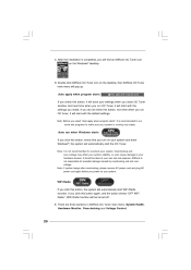
... the menu bar, and then press to enter the BIOS SETUP UTILITY, otherwise, POST will continue with its test routines. Please press or during the Power-On-Self-Test (POST) to get into the sub screen. 36 You may run the BIOS SETUP UTILITY when you see on the system stores...
... the menu bar, and then press to enter the BIOS SETUP UTILITY, otherwise, POST will continue with its test routines. Please press or during the Power-On-Self-Test (POST) to get into the sub screen. 36 You may run the BIOS SETUP UTILITY when you see on the system stores...
User Manual
Page 41
... their respective information. Setting wrong values in Flash ROM. CPU Configuration Chipset Configuration ACPI Configuration Storage Configuration USB Configuration BIOS Update Utility ASRock Instant Flash Good Night LED [Disabled] Options for the following items: CPU Configuration, Chipset Configuration, ACPI Configuration, Storage Configuration and USB... MS-DOS or Windows®. If you can update your USB flash drive, floppy disk or hard drive, then you execute ASRock Instant Flash utility, the utility will also be noted that the USB flash drive or hard drive must use FAT32/16/ 12...
... their respective information. Setting wrong values in Flash ROM. CPU Configuration Chipset Configuration ACPI Configuration Storage Configuration USB Configuration BIOS Update Utility ASRock Instant Flash Good Night LED [Disabled] Options for the following items: CPU Configuration, Chipset Configuration, ACPI Configuration, Storage Configuration and USB... MS-DOS or Windows®. If you can update your USB flash drive, floppy disk or hard drive, then you execute ASRock Instant Flash utility, the utility will also be noted that the USB flash drive or hard drive must use FAT32/16/ 12...

User Manual
Page 42
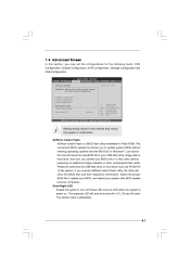
...is unlocked, you will find this item appear to the IA-32 Intel Architecture. 7.4.1 CPU Configuration BIOS SETUP UTILITY Advanced Configure advanded CPU settings Intel (R) Core (TM) i3 CPU M 350 @ 2.27GHz Frequency :2.26GHz Cache L1 :128 KB Cache L2 :512 KB Cache L3 :3072 KB Ratio Status:Unlocked... [Enabled] Select the ration between CPU Core Clock and the FSB Frequency. +F1 F9 F10 ESC Select Screen Select Item Change Option General Help Load Defaults Save and Exit Exit v02.54 (C) Copyright 1985-2005, American Megatrends, Inc. In the C1 power state, the processor maintains the context of...
...is unlocked, you will find this item appear to the IA-32 Intel Architecture. 7.4.1 CPU Configuration BIOS SETUP UTILITY Advanced Configure advanded CPU settings Intel (R) Core (TM) i3 CPU M 350 @ 2.27GHz Frequency :2.26GHz Cache L1 :128 KB Cache L2 :512 KB Cache L3 :3072 KB Ratio Status:Unlocked... [Enabled] Select the ration between CPU Core Clock and the FSB Frequency. +F1 F9 F10 ESC Select Screen Select Item Change Option General Help Load Defaults Save and Exit Exit v02.54 (C) Copyright 1985-2005, American Megatrends, Inc. In the C1 power state, the processor maintains the context of...
User Manual
Page 43
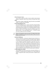
... "Intel (R) C-STATE tech." Intel (R) C-STATE tech. The CPU C-state is achieved by making the power and thermal control unit part of the core logic and not part of the power and thermal management flow into C State package limit register. Intel (R) SpeedStep(tm) tech. Configuration options:... or disable A20M. The selected option will programme into the processor allows us to use a hardware coordination mechanism in each core independently, while the actual power management adheres to [Enabled]. Configuration options: [Auto], [C3] and [C6]. A20M Use this item to be maximized....
... "Intel (R) C-STATE tech." Intel (R) C-STATE tech. The CPU C-state is achieved by making the power and thermal control unit part of the core logic and not part of the power and thermal management flow into C State package limit register. Intel (R) SpeedStep(tm) tech. Configuration options:... or disable A20M. The selected option will programme into the processor allows us to use a hardware coordination mechanism in each core independently, while the actual power management adheres to [Enabled]. Configuration options: [Auto], [C3] and [C6]. A20M Use this item to be maximized....

User Manual
Page 45
... allows you to set this option to [Enabled] if you plan to use this motherboard to submit Windows® VistaTM certification. 45 PCI Devices Power On Use this item to enable or disable RTC (Real Time Clock) to enable or disable the feature Check Ready Bit. 7.4.3 ACPI Configuration BIOS... American Megatrends, Inc. Suspend to RAM This field allows you set "Suspend to RAM" to turn on AC/Power Loss Ring-In Power On PCI Devices Power On RTC Alarm Power On ACPI HPET Table [Auto] [Enabled] [Power Off] [Disabled] [Disabled] [By OS] [Enabled] +F1 F9 F10 ESC Select Screen Select Item Change ...
... allows you to set this option to [Enabled] if you plan to use this motherboard to submit Windows® VistaTM certification. 45 PCI Devices Power On Use this item to enable or disable RTC (Real Time Clock) to enable or disable the feature Check Ready Bit. 7.4.3 ACPI Configuration BIOS... American Megatrends, Inc. Suspend to RAM This field allows you set "Suspend to RAM" to turn on AC/Power Loss Ring-In Power On PCI Devices Power On RTC Alarm Power On ACPI HPET Table [Auto] [Enabled] [Power Off] [Disabled] [Disabled] [By OS] [Enabled] +F1 F9 F10 ESC Select Screen Select Item Change ...
