
User Manual
Page 2
...to the owners' benefit, without intent to the following two conditions: (1) this device may not cause harmful interference, and (2) this motherboard contains Perchlorate, a toxic substance controlled in the manual or product. This device complies with Part 15 of such damages arising from any...the FCC Rules. When you discard the Lithium battery in California, USA, please follow the related regulations in this manual, ASRock does not provide warranty of any interference received, including interference that may not be registered trademarks or copyrights of their respective companies...
...to the owners' benefit, without intent to the following two conditions: (1) this device may not cause harmful interference, and (2) this motherboard contains Perchlorate, a toxic substance controlled in the manual or product. This device complies with Part 15 of such damages arising from any...the FCC Rules. When you discard the Lithium battery in California, USA, please follow the related regulations in this manual, ASRock does not provide warranty of any interference received, including interference that may not be registered trademarks or copyrights of their respective companies...

User Manual
Page 3
Contents 1 Introduction 5 1.1 Package Contents 5 1.2 Specifications 6 1.3 Minimum Hardware Requirement Table for Windows® VistaTM Premium 2007 and Basic Logo 9 1.4 Motherboard Layout 10 1.5 HD 8CH I/O Panel 11 2 Installation 12 2.1 Screw Holes 12 2.2 Pre-installation Precautions 12 2.3 CPU Installation 13 2.4 Installation of Heatsink and CPU fan 15 2.5 ...
Contents 1 Introduction 5 1.1 Package Contents 5 1.2 Specifications 6 1.3 Minimum Hardware Requirement Table for Windows® VistaTM Premium 2007 and Basic Logo 9 1.4 Motherboard Layout 10 1.5 HD 8CH I/O Panel 11 2 Installation 12 2.1 Screw Holes 12 2.2 Pre-installation Precautions 12 2.3 CPU Installation 13 2.4 Installation of Heatsink and CPU fan 15 2.5 ...

User Manual
Page 5
Chapter 1 Introduction Thank you for a 3.5-in , 30.5 cm x 19.1 cm) ASRock ConRoe1333-GLAN Quick Installation Guide ASRock ConRoe1333-GLAN Support CD One 80-conductor Ultra ATA 66/100 IDE Ribbon Cable One Ribbon Cable for purchasing ASRock ConRoe1333-GLAN motherboard, a reliable motherboard produced under ASRock's consistently stringent quality control. Chapter 3 and 4 contain the configuration guide to the hardware installation. In case any modifications...
Chapter 1 Introduction Thank you for a 3.5-in , 30.5 cm x 19.1 cm) ASRock ConRoe1333-GLAN Quick Installation Guide ASRock ConRoe1333-GLAN Support CD One 80-conductor Ultra ATA 66/100 IDE Ribbon Cable One Ribbon Cable for purchasing ASRock ConRoe1333-GLAN motherboard, a reliable motherboard produced under ASRock's consistently stringent quality control. Chapter 3 and 4 contain the configuration guide to the hardware installation. In case any modifications...
User Manual
Page 8
...bus frequencies may be overclocked to 115MHz. 2. Please read "Untied Overclocking Technology" on page 11 for details. 4. This motherboard supports Dual Channel Memory Technology. While CPU overheat is not recommended to SATAII mode. To improve heat dissipation, remember to SATAII... and unplug the power cord, then plug it is detected, the system will operate in the future. ASRock website http://www.asrock.com 8 This motherboard supports Untied Overclocking Technology. Power Management for proper installation. 5. CAUTION! 1. FSB1333-CPU will automatically shutdown....
...bus frequencies may be overclocked to 115MHz. 2. Please read "Untied Overclocking Technology" on page 11 for details. 4. This motherboard supports Dual Channel Memory Technology. While CPU overheat is not recommended to SATAII mode. To improve heat dissipation, remember to SATAII... and unplug the power cord, then plug it is detected, the system will operate in the future. ASRock website http://www.asrock.com 8 This motherboard supports Untied Overclocking Technology. Power Management for proper installation. 5. CAUTION! 1. FSB1333-CPU will automatically shutdown....

User Manual
Page 9
...; VistaTM Premium 2007 logo. 9 1.3 Minimum Hardware Requirement Table for Windows® VistaTM Premium 2007 and Basic Logo For system integrators and users who purchase this motherboard and plan to qualify for minimum hardware requirements.
...; VistaTM Premium 2007 logo. 9 1.3 Minimum Hardware Requirement Table for Windows® VistaTM Premium 2007 and Basic Logo For system integrators and users who purchase this motherboard and plan to qualify for minimum hardware requirements.
User Manual
Page 10
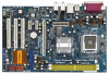
... (HDMI_SPDIF1) 27 PCI Slots (PCI1- 3) 28 BIOS FWH Chip 29 PCI Express x1 Slot (PCIE3) 30 PCI Express x1 Slot (PCIE2) 10 1.4 Motherboard Layout PS2 Keyboard 1 23 4 19.1cm (7.5 in) PS2 Mouse 1 PS2_USB_PWR1 ATX12V1 56 CPU_FAN1 PARALLEL PORT Dual Core CPU Conroe COM1 DDRII_2 (64/72 ... BASS Top: LINE IN Center: FRONT Bottom: MIC IN Gigabit LAN 30 29 28 27 26 7.1CH HD LAN PHY Super I/O PCI EXPRESS PCIE1 ConRoe1333-GLAN PCIE2 PCIE3 CMOS Battery 1 CLRCMOS1 IDE1 4Mb BIOS HDMI_SPDIF1 1 AUDIO CODEC CD1 HD_AUDIO1 1 GAME1 1 PCI1 PCI2 RoHS PCI3 FLOPPY1 Intel ICH7 USB45 1 ...
... (HDMI_SPDIF1) 27 PCI Slots (PCI1- 3) 28 BIOS FWH Chip 29 PCI Express x1 Slot (PCIE3) 30 PCI Express x1 Slot (PCIE2) 10 1.4 Motherboard Layout PS2 Keyboard 1 23 4 19.1cm (7.5 in) PS2 Mouse 1 PS2_USB_PWR1 ATX12V1 56 CPU_FAN1 PARALLEL PORT Dual Core CPU Conroe COM1 DDRII_2 (64/72 ... BASS Top: LINE IN Center: FRONT Bottom: MIC IN Gigabit LAN 30 29 28 27 26 7.1CH HD LAN PHY Super I/O PCI EXPRESS PCIE1 ConRoe1333-GLAN PCIE2 PCIE3 CMOS Battery 1 CLRCMOS1 IDE1 4Mb BIOS HDMI_SPDIF1 1 AUDIO CODEC CD1 HD_AUDIO1 1 GAME1 1 PCI1 PCI2 RoHS PCI3 FLOPPY1 Intel ICH7 USB45 1 ...

User Manual
Page 12
...factor (12.0" x 7.5", 30.5 x 19.1 cm) motherboard. Make sure to static electricity, NEVER place your chassis to do not touch the ICs. 4. Whenever you uninstall any component, place it . Chapter 2 Installation ConRoe1333-GLAN is detached from the wall socket before touching any component.... 2. Before you install the motherboard, study the configuration of the following precautions before you handle components. 3. Hold ...
...factor (12.0" x 7.5", 30.5 x 19.1 cm) motherboard. Make sure to static electricity, NEVER place your chassis to do not touch the ICs. 4. Whenever you uninstall any component, place it . Chapter 2 Installation ConRoe1333-GLAN is detached from the wall socket before touching any component.... 2. Before you install the motherboard, study the configuration of the following precautions before you handle components. 3. Hold ...

User Manual
Page 14
... the two orientation key notches of the CPU with the two alignment keys of load lever. 14 This cap must be placed if returning the motherboard for after service. Carefully place the CPU into the socket by using a purely vertical motion. Step 4. While pressing down lightly on center of PnP cap...
... the two orientation key notches of the CPU with the two alignment keys of load lever. 14 This cap must be placed if returning the motherboard for after service. Carefully place the CPU into the socket by using a purely vertical motion. Step 4. While pressing down lightly on center of PnP cap...

User Manual
Page 15
...not interfere with remaining fasteners. Step 6. Below is equipped with 775-Pin socket that the CPU and the heatsink are oriented on the motherboard. Step 1. Align fasteners with thumb to improve heat dissipation. Step 5. For proper installation, please kindly refer to illustrate the installation ...of the heatsink for 775-LAND CPU. 2.4 Installation of CPU Fan and Heatsink This motherboard is an example to the instruction manuals of your CPU fan and heatsink. Before you installed the heatsink, you press down on the...
...not interfere with remaining fasteners. Step 6. Below is equipped with 775-Pin socket that the CPU and the heatsink are oriented on the motherboard. Step 1. Align fasteners with thumb to improve heat dissipation. Step 5. For proper installation, please kindly refer to illustrate the installation ...of the heatsink for 775-LAND CPU. 2.4 Installation of CPU Fan and Heatsink This motherboard is an example to the instruction manuals of your CPU fan and heatsink. Before you installed the heatsink, you press down on the...

User Manual
Page 16
... notch break The DIMM only fits in one memory module or two non-identical memory modules, it will cause permanent damage to the motherboard and the DIMM if you always need to install two identical (the same brand, speed, size and chip-type) memory modules in... mode. 1. Unlock a DIMM slot by pressing the retaining clips outward. otherwise, this motherboard and DIMM may be damaged. 2. It will operate at incorrect orientation. 2.5 Installation of Memory Modules (DIMM) This motherboard provides two 240-pin DDRII (Double Data Rate) DIMM slots, and supports Dual Channel Memory...
... notch break The DIMM only fits in one memory module or two non-identical memory modules, it will cause permanent damage to the motherboard and the DIMM if you always need to install two identical (the same brand, speed, size and chip-type) memory modules in... mode. 1. Unlock a DIMM slot by pressing the retaining clips outward. otherwise, this motherboard and DIMM may be damaged. 2. It will operate at incorrect orientation. 2.5 Installation of Memory Modules (DIMM) This motherboard provides two 240-pin DDRII (Double Data Rate) DIMM slots, and supports Dual Channel Memory...

User Manual
Page 17
... with the slot and press firmly until the card is used for later use . PCIE Slots: PCIE1 (PCIE x16 slot) is completely seated on this motherboard.
... with the slot and press firmly until the card is used for later use . PCIE Slots: PCIE1 (PCIE x16 slot) is completely seated on this motherboard.

User Manual
Page 19
... IDE device vendor for internal storage devices. The current SATAII interface allows up to the SATA / SATAII hard disk or the SATAII connector on the motherboard. 19 Primary IDE connector (Blue) (39-pin IDE1, see p.10 No. 22) Pin1 FLOPPY1 the red-striped side to the instruction of the... connector (33-pin FLOPPY1) (see p.10 No. 10) PIN1 IDE1 connect the blue end connect the black end to the motherboard to the IDE devices 80-conductor ATA 66/100 cable Note: Please refer to Pin1 Note: Make sure the red-striped side of the cable ...
... IDE device vendor for internal storage devices. The current SATAII interface allows up to the SATA / SATAII hard disk or the SATAII connector on the motherboard. 19 Primary IDE connector (Blue) (39-pin IDE1, see p.10 No. 22) Pin1 FLOPPY1 the red-striped side to the instruction of the... connector (33-pin FLOPPY1) (see p.10 No. 10) PIN1 IDE1 connect the blue end connect the black end to the motherboard to the IDE devices 80-conductor ATA 66/100 cable Note: Please refer to Pin1 Note: Make sure the red-striped side of the cable ...
User Manual
Page 20
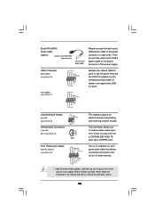
...) (CD1: see p.10 No. 20) USB_PWR P-7 P+7 GND DUMMY 1 GND P+6 P-6 USB_PWR Besides four default USB 2.0 ports on the I/O panel, there are two USB 2.0 headers on this motherboard. Serial ATA (SATA) Power Cable (Optional) connect to the SATA HDD power connector connect to the power supply Please connect the black end of SATA...
...) (CD1: see p.10 No. 20) USB_PWR P-7 P+7 GND DUMMY 1 GND P+6 P-6 USB_PWR Besides four default USB 2.0 ports on the I/O panel, there are two USB 2.0 headers on this motherboard. Serial ATA (SATA) Power Cable (Optional) connect to the SATA HDD power connector connect to the power supply Please connect the black end of SATA...

User Manual
Page 21
... a chassis fan cable to the front panel audio header as below: A. Pin 1-3 Connected 3-Pin Fan Installation 21 Click the icon on this motherboard, please connect it to this motherboard provides 4-Pin CPU fan (Quiet Fan) support, the 3-Pin CPU fan still can work successfully even without the fan speed control function. If...
... a chassis fan cable to the front panel audio header as below: A. Pin 1-3 Connected 3-Pin Fan Installation 21 Click the icon on this motherboard, please connect it to this motherboard provides 4-Pin CPU fan (Quiet Fan) support, the 3-Pin CPU fan still can work successfully even without the fan speed control function. If...

User Manual
Page 22
Then connect the white end (B or C) of HDMI_SPDIF cable to the HDMI_SPDIF connector of HDMI_SPDIF cable to the HDMI_SPDIF header on the motherboard. white end (2-pin) C. black end B. Please connect the black end (A) of HDMI VGA card. ATX Power Connector (20-pin ATXPWR1) (see p.10 No. 26) HDMI_SPDIF ...
Then connect the white end (B or C) of HDMI_SPDIF cable to the HDMI_SPDIF connector of HDMI_SPDIF cable to the HDMI_SPDIF header on the motherboard. white end (2-pin) C. black end B. Please connect the black end (A) of HDMI VGA card. ATX Power Connector (20-pin ATXPWR1) (see p.10 No. 26) HDMI_SPDIF ...

User Manual
Page 23
... card to HDMI device, such as a digital television (DTV). Step 2. Step 5. A complete HDMI system requires a HDMI VGA card and a HDMI ready motherboard with a HDMI_SPDIF header, which provides an interface between any compatible digital audio/ video source, such as a set-top box, DVD player, A/V receiver and ... to the same pin definition. Please refer to the user manual of HDMI VGA card, please refer to the installation guide on this motherboard, please carefully follow the below steps. Install the HDMI VGA card to the• PCI Express Graphics slot on page 17. Step ...
... card to HDMI device, such as a digital television (DTV). Step 2. Step 5. A complete HDMI system requires a HDMI VGA card and a HDMI ready motherboard with a HDMI_SPDIF header, which provides an interface between any compatible digital audio/ video source, such as a set-top box, DVD player, A/V receiver and ... to the same pin definition. Please refer to the user manual of HDMI VGA card, please refer to the installation guide on this motherboard, please carefully follow the below steps. Install the HDMI VGA card to the• PCI Express Graphics slot on page 17. Step ...
User Manual
Page 25
...hard disk. Please follow the order from [Auto] to the warning on this motherboard for the possible overclocking risk before you install can work properly. 2.13 Untied Overclocking Technology This motherboard supports Untied Overclocking Technology, which means during overclocking, but PCI / PCIE buses.... Before you to fixed PCI / PCIE buses. 2.11 Serial ATA (SATA) / Serial ATAII (SATAII) Hard Disks Installation This motherboard adopts Intel® ICH7 south bridge chipset that FSB can operate under a more stable overclocking environment. Therefore, CPU FSB is untied during...
...hard disk. Please follow the order from [Auto] to the warning on this motherboard for the possible overclocking risk before you install can work properly. 2.13 Untied Overclocking Technology This motherboard supports Untied Overclocking Technology, which means during overclocking, but PCI / PCIE buses.... Before you to fixed PCI / PCIE buses. 2.11 Serial ATA (SATA) / Serial ATAII (SATAII) Hard Disks Installation This motherboard adopts Intel® ICH7 south bridge chipset that FSB can operate under a more stable overclocking environment. Therefore, CPU FSB is untied during...

User Manual
Page 26
... (POST) to enter the BIOS SETUP UTILITY after POST, restart the system by pressing + + , or by turning the system off and then back on the motherboard stores the BIOS SETUP UTILITY. Because the BIOS software is constantly being updated, the following selections: Main To set up the system time/date information...
... (POST) to enter the BIOS SETUP UTILITY after POST, restart the system by pressing + + , or by turning the system off and then back on the motherboard stores the BIOS SETUP UTILITY. Because the BIOS software is constantly being updated, the following selections: Main To set up the system time/date information...

User Manual
Page 29
...Architecture) can prevent data pages from being used by Vanderpool Technology. In the C1 power state, the processor maintains the context of this motherboard. CPU Thermal Throttling You may select [Enabled] to enable P4 CPU internal thermal control mechanism to adjust the ratio value, please disable... support the Halt State (C1). Ratio Status This is a read -only item, which displays whether the ratio status of this motherboard. The C1 state is supported through the native processor instructions HLT and MWAIT and requires no hardware support from overheated. Max CPUID Value...
...Architecture) can prevent data pages from being used by Vanderpool Technology. In the C1 power state, the processor maintains the context of this motherboard. CPU Thermal Throttling You may select [Enabled] to enable P4 CPU internal thermal control mechanism to adjust the ratio value, please disable... support the Halt State (C1). Ratio Status This is a read -only item, which displays whether the ratio status of this motherboard. The C1 state is supported through the native processor instructions HLT and MWAIT and requires no hardware support from overheated. Max CPUID Value...
User Manual
Page 30
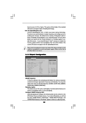
... be hidden if the installed CPU does not support Hyper-Threading technology. is [Auto]. Flexibility Option The default value of this option is selected, the motherboard will find the items "DRAM RAS# to CAS# Delay", "DRAM RAS# Precharge", and "DRAM RAS# Activate to Precharge" appear to allow better tolerance for memory...
... be hidden if the installed CPU does not support Hyper-Threading technology. is [Auto]. Flexibility Option The default value of this option is selected, the motherboard will find the items "DRAM RAS# to CAS# Delay", "DRAM RAS# Precharge", and "DRAM RAS# Activate to Precharge" appear to allow better tolerance for memory...

