
User Manual
Page 3
...Holes 12 2.2 Pre-installation Precautions 12 2.3 CPU Installation 13 2.4 Installation of Heatsink and CPU fan 15 2.5 Installation of Memory Modules (DIMM 16 2.6 Expansion Slots (PCI, HDMR, and PCI Express Slots) ....... 18 2.7 DVI Graphics-HDCP Card Installation Guide 19 2.8 Jumpers...UTILITY 28 3.1 Introduction 28 3.1.1 BIOS Menu Bar 28 3.1.2 Navigation Keys 29 3.2 Main Screen 29 3.3 Advanced Screen 29 3.3.1 CPU Configuration 30 3.3.2 Chipset Configuration 32 3.3.3 ACPI Configuration 35 3.3.4 IDE Configuration 36 3.3.5 PCIPnP Configuration 38 3.3.6 Floppy Configuration 39 3.3.7...
...Holes 12 2.2 Pre-installation Precautions 12 2.3 CPU Installation 13 2.4 Installation of Heatsink and CPU fan 15 2.5 Installation of Memory Modules (DIMM 16 2.6 Expansion Slots (PCI, HDMR, and PCI Express Slots) ....... 18 2.7 DVI Graphics-HDCP Card Installation Guide 19 2.8 Jumpers...UTILITY 28 3.1 Introduction 28 3.1.1 BIOS Menu Bar 28 3.1.2 Navigation Keys 29 3.2 Main Screen 29 3.3 Advanced Screen 29 3.3.1 CPU Configuration 30 3.3.2 Chipset Configuration 32 3.3.3 ACPI Configuration 35 3.3.4 IDE Configuration 36 3.3.5 PCIPnP Configuration 38 3.3.6 Floppy Configuration 39 3.3.7...

User Manual
Page 5
... IDE Ribbon Cable One Ribbon Cable for purchasing ASRock ConRoe1333-DVI/H motherboard, a reliable motherboard produced under ASRock's consistently stringent quality control. In case any modifications of this manual will be subject to quality and endurance. You may find the latest VGA cards and CPU support lists on ASRock website without notice. In this manual occur, the...
... IDE Ribbon Cable One Ribbon Cable for purchasing ASRock ConRoe1333-DVI/H motherboard, a reliable motherboard produced under ASRock's consistently stringent quality control. In case any modifications of this manual will be subject to quality and endurance. You may find the latest VGA cards and CPU support lists on ASRock website without notice. In this manual occur, the...

User Manual
Page 6
... CAUTION 1) - Intel® Graphics Media Accelerator 950 - Pixel Shader 2.0, DirectX 9.0 - Dual VGA Output: support D-Sub and DVI-D ports with DVI Graphics-HDCP card - 7.1 CH Windows® VistaTM Premium Level HD Audio (ALC888 Audio Codec) - Realtek RTL8111B - Compatible with all... 6) - ASRock U-COP (see CAUTION 7) - PCIE x1 Gigabit LAN 10/100/1000 Mb/s - LGA 775 for Intel® Dual Core CoreTM 2 Extreme / CoreTM 2 Duo / Pentium® D / Pentium® 4 / Celeron® D - Max. CPU Frequency Stepless Control (see CAUTION 8) - Supports EM64T CPU - Boot Failure...
... CAUTION 1) - Intel® Graphics Media Accelerator 950 - Pixel Shader 2.0, DirectX 9.0 - Dual VGA Output: support D-Sub and DVI-D ports with DVI Graphics-HDCP card - 7.1 CH Windows® VistaTM Premium Level HD Audio (ALC888 Audio Codec) - Realtek RTL8111B - Compatible with all... 6) - ASRock U-COP (see CAUTION 7) - PCIE x1 Gigabit LAN 10/100/1000 Mb/s - LGA 775 for Intel® Dual Core CoreTM 2 Extreme / CoreTM 2 Duo / Pentium® D / Pentium® 4 / Celeron® D - Max. CPU Frequency Stepless Control (see CAUTION 8) - Supports EM64T CPU - Boot Failure...
User Manual
Page 7
... that there is a certain risk involved with overclocking, including adjusting the setting in header - CPU/Chassis FAN connector - 20 pin ATX power connector - 4 pin 12V power connector - Supports jumperfree - CPU Quiet Fan - Overclocking may affect your system stability, or even cause damage to the components and... devices of your own risk and expense. CPU Fan Tachometer - Connector BIOS Feature Support CD Hardware Monitor OS Certifications - HD Audio Jack: Side Speaker/Rear Speaker/Central/Bass/ ...
... that there is a certain risk involved with overclocking, including adjusting the setting in header - CPU/Chassis FAN connector - 20 pin ATX power connector - 4 pin 12V power connector - Supports jumperfree - CPU Quiet Fan - Overclocking may affect your system stability, or even cause damage to the components and... devices of your own risk and expense. CPU Fan Tachometer - Connector BIOS Feature Support CD Hardware Monitor OS Certifications - HD Audio Jack: Side Speaker/Rear Speaker/Central/Bass/ ...
User Manual
Page 8
... the heatsink when you adopt a DDRII533 memory module. 6. You can also connect SATA hard disk to perform over-clocking. ASRock website http://www.asrock.com 8 Before you resume the system, please check if the CPU fan on page 11 for proper installation. 5. Although this motherboard supports 2-channel, 4-channel, 6-channel, and 8-channel modes. CAUTION...
... the heatsink when you adopt a DDRII533 memory module. 6. You can also connect SATA hard disk to perform over-clocking. ASRock website http://www.asrock.com 8 Before you resume the system, please check if the CPU fan on page 11 for proper installation. 5. Although this motherboard supports 2-channel, 4-channel, 6-channel, and 8-channel modes. CAUTION...
User Manual
Page 9
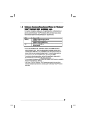
CPU Memory VGA Celeron D 326 512MB x 2 Dual Channel (Premium) 512MB Single Channel (Basic) 256MB x 2 Dual Channel (Basic) DX9.0 with VDDM Driver DVI with HDCP * If you use onboard VGA with total system memory size 512MB and plan to submit Windows® VistaTM Basic logo, ... 2007 and Basic Logo For system integrators and users who purchase this motherboard, please refer to Premium Discrete requirement at http://www.asrock.com * If the onboard VGA supports DVI, it must also support HDCP function to qualify for Windows® VistaTM Premium 2007 logo. * After June 1, 2007, all Windows...
CPU Memory VGA Celeron D 326 512MB x 2 Dual Channel (Premium) 512MB Single Channel (Basic) 256MB x 2 Dual Channel (Basic) DX9.0 with VDDM Driver DVI with HDCP * If you use onboard VGA with total system memory size 512MB and plan to submit Windows® VistaTM Basic logo, ... 2007 and Basic Logo For system integrators and users who purchase this motherboard, please refer to Premium Discrete requirement at http://www.asrock.com * If the onboard VGA supports DVI, it must also support HDCP function to qualify for Windows® VistaTM Premium 2007 logo. * After June 1, 2007, all Windows...

User Manual
Page 10
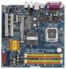
... Connector (CPU_FAN1) 17 Chassis Fan Connector (CHA_FAN1) 4 775-Pin CPU Socket 18 USB 2.0 Header (USB6_7, Blue) 5 North Bridge Controller 19 USB 2.0 Header (USB4_5, Blue) 6 Clear CMOS Jumper (CLRCMOS1) 20 Floppy Connector (FLOPPY1) 7 2 ...HD HDMR1 FLOPPY1 Intel ICH7 SATAII 1 USB4_5 IDE1 1 USB6_7 SATAII_3 SATAII_1 USB2.0 CHA_FAN1 SATAII_4 SATAII_2 SPEAKER1 1 PANEL 1 PLED PWRBTN 1 HDLED RESET Dual Core CPU Dual Channel ConRoe1333-DVI/H 22 21 20 19 18 17 161514 13 DDRII667 24.4cm (9.6 in) 9 10 11 12 1 PS2_USB_PWR1 Jumper 15 Third SATAII Connector (SATAII_3; Orange)...
... Connector (CPU_FAN1) 17 Chassis Fan Connector (CHA_FAN1) 4 775-Pin CPU Socket 18 USB 2.0 Header (USB6_7, Blue) 5 North Bridge Controller 19 USB 2.0 Header (USB4_5, Blue) 6 Clear CMOS Jumper (CLRCMOS1) 20 Floppy Connector (FLOPPY1) 7 2 ...HD HDMR1 FLOPPY1 Intel ICH7 SATAII 1 USB4_5 IDE1 1 USB6_7 SATAII_3 SATAII_1 USB2.0 CHA_FAN1 SATAII_4 SATAII_2 SPEAKER1 1 PANEL 1 PLED PWRBTN 1 HDLED RESET Dual Core CPU Dual Channel ConRoe1333-DVI/H 22 21 20 19 18 17 161514 13 DDRII667 24.4cm (9.6 in) 9 10 11 12 1 PS2_USB_PWR1 Jumper 15 Third SATAII Connector (SATAII_3; Orange)...

User Manual
Page 13
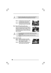
... 100 degrees. Step 1. Rotate the load plate to insert the CPU into the socket, please check if the CPU surface is unclean or if there is found. Orient the CPU with black lines. Insert the 775-LAND CPU: Step 2-1. Hold the CPU by depressing down and out on the socket. Otherwise, the... orientation key notch Pin1 alignment key alignment key 775-LAND CPU 775-Pin Socket 13 2.3 CPU Installation For the installation of Intel 775-LAND CPU, please follow the steps below. 775-Pin Socket Overview Before you insert the 775-LAND CPU into the socket if above situation is any bent pin...
... 100 degrees. Step 1. Rotate the load plate to insert the CPU into the socket, please check if the CPU surface is unclean or if there is found. Orient the CPU with black lines. Insert the 775-LAND CPU: Step 2-1. Hold the CPU by depressing down and out on the socket. Otherwise, the... orientation key notch Pin1 alignment key alignment key 775-LAND CPU 775-Pin Socket 13 2.3 CPU Installation For the installation of Intel 775-LAND CPU, please follow the steps below. 775-Pin Socket Overview Before you insert the 775-LAND CPU into the socket if above situation is any bent pin...
User Manual
Page 14
... the socket and properly mated to handle and avoid kicking off the PnP cap. 2. Rotate the load plate onto the IHS. Step 4-3. Verify that the CPU is recommended to use the cap tab to the orient keys. While pressing down lightly on center of PnP cap to assist in removal. 1. Step... 4. For proper inserting, please ensure to match the two orientation key notches of the CPU with load plate tab under retention tab of load lever. 14 Close the socket: Step 4-1. Secure load lever with the two alignment keys of the...
... the socket and properly mated to handle and avoid kicking off the PnP cap. 2. Rotate the load plate onto the IHS. Step 4-3. Verify that the CPU is recommended to use the cap tab to the orient keys. While pressing down lightly on center of PnP cap to assist in removal. 1. Step... 4. For proper inserting, please ensure to match the two orientation key notches of the CPU with load plate tab under retention tab of load lever. 14 Close the socket: Step 4-1. Secure load lever with the two alignment keys of the...
User Manual
Page 15
... to improve heat dissipation. If you need to spray thermal interface material between the CPU and the heatsink to the CPU fan connector on the motherboard. Below is equipped with Intel 775-LAND CPU to install and lock. Place the heatsink onto the socket. Ensure fan cables are... contact with thumb to dissipate heat. Please adopt the type of the heatsink for 775-LAND CPU. For proper installation, please kindly refer to ensure cable does not interfere with the CPU fan connector on fastener caps with each other components. 15 Step 3. Align fasteners with remaining ...
... to improve heat dissipation. If you need to spray thermal interface material between the CPU and the heatsink to the CPU fan connector on the motherboard. Below is equipped with Intel 775-LAND CPU to install and lock. Place the heatsink onto the socket. Ensure fan cables are... contact with thumb to dissipate heat. Please adopt the type of the heatsink for 775-LAND CPU. For proper installation, please kindly refer to ensure cable does not interfere with the CPU fan connector on fastener caps with each other components. 15 Step 3. Align fasteners with remaining ...
User Manual
Page 24
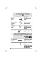
... (4-pin CPU_FAN1) (see p.10 No. 3) +12V CPU_FAN_SPEED GND FAN_SPEED_CONTROL 1 2 3 4 Please connect a CPU fan cable to this motherboard provides 4-Pin CPU fan (Quiet Fan) support, the 3-Pin CPU fan still can provides sufficient power. ATX 12V Connector (4-pin ATX12V1) (see p.10 No. 17) GND +12V CHA_FAN_SPEED ...wire to enter Realtek HD Audio Manager. Click the icon on this connector. F. If you plan to connect the 3-Pin CPU fan to the CPU fan connector on the lower right hand taskbar to the ground pin. Enter Windows system. Please connect the chassis speaker to...
... (4-pin CPU_FAN1) (see p.10 No. 3) +12V CPU_FAN_SPEED GND FAN_SPEED_CONTROL 1 2 3 4 Please connect a CPU fan cable to this motherboard provides 4-Pin CPU fan (Quiet Fan) support, the 3-Pin CPU fan still can provides sufficient power. ATX 12V Connector (4-pin ATX12V1) (see p.10 No. 17) GND +12V CHA_FAN_SPEED ...wire to enter Realtek HD Audio Manager. Click the icon on this connector. F. If you plan to connect the 3-Pin CPU fan to the CPU fan connector on the lower right hand taskbar to the ground pin. Enter Windows system. Please connect the chassis speaker to...

User Manual
Page 27
...Serial ATAII (SATAII) hard disks. Then, the drivers compatible to install the SATA / SATAII hard disks. Before you to your chassis. Therefore, CPU FSB is completely seated on this motherboard, and you finish installing all drivers to your system now, but PCI / PCIE buses are in the future..., FSB enjoys better margin due to the warning on the support CD driver page. Install HDMR card driver from up to bottom side to [CPU, PCIE, Async.]. 2.11 Serial ATA (SATA) / Serial ATAII (SATAII) Hard Disks Installation This motherboard adopts Intel® ICH7 south bridge ...
...Serial ATAII (SATAII) hard disks. Then, the drivers compatible to install the SATA / SATAII hard disks. Before you to your chassis. Therefore, CPU FSB is completely seated on this motherboard, and you finish installing all drivers to your system now, but PCI / PCIE buses are in the future..., FSB enjoys better margin due to the warning on the support CD driver page. Install HDMR card driver from up to bottom side to [CPU, PCIE, Async.]. 2.11 Serial ATA (SATA) / Serial ATAII (SATAII) Hard Disks Installation This motherboard adopts Intel® ICH7 south bridge ...

User Manual
Page 29
... Save and Exit Exit v02.54 (C) Copyright 1985-2005, American Megatrends, Inc. 3.1.2 Navigation Keys Please check the following items: CPU Configuration, Chipset Configuration, ACPI Configuration, IDE Configuration, PCIPnP Configuration, Floppy Configuration, SuperIO Configuration, and USB Configuration. 29 System Time ... Monitor Boot System Overview System Time System Date [14:00:09] [Thu 01/18/2007] BIOS Version : ConRoe1333-DVI/H BIOS P1.00 Processor Type : Intel (R) CPU 3.40 GHz (64bit supported) Processor Speed : 3400 MHz Microcode Update : F34/17 Cache Size : 1024KB Total ...
... Save and Exit Exit v02.54 (C) Copyright 1985-2005, American Megatrends, Inc. 3.1.2 Navigation Keys Please check the following items: CPU Configuration, Chipset Configuration, ACPI Configuration, IDE Configuration, PCIPnP Configuration, Floppy Configuration, SuperIO Configuration, and USB Configuration. 29 System Time ... Monitor Boot System Overview System Time System Date [14:00:09] [Thu 01/18/2007] BIOS Version : ConRoe1333-DVI/H BIOS P1.00 Processor Type : Intel (R) CPU 3.40 GHz (64bit supported) Processor Speed : 3400 MHz Microcode Update : F34/17 Cache Size : 1024KB Total ...

User Manual
Page 30
...item should always be [Auto] for better system stability. 30 The default value is [Auto]. Cnfiguration options: [Auto], [CPU, PCIE, Sync.] and [CPU, PCIE, Async.]. BIOS SETUP UTILITY Main Advanced H/W Monitor Boot Security Exit Advanced Settings WARNING : Setting wrong values in ... cause system to Sub Screen F1 General Help F9 Load Defaults F10 Save and Exit ESC Exit v02.54 (C) Copyright 1985-2005, American Megatrends, Inc. CPU Thermal Throttling No-Excute Memory Protection Hyper Threading Technology Intel (R) SpeedStep(tm) tech. [Auto] [133] [100] [Enabled] [Auto] 9 [Disabled]...
...item should always be [Auto] for better system stability. 30 The default value is [Auto]. Cnfiguration options: [Auto], [CPU, PCIE, Sync.] and [CPU, PCIE, Async.]. BIOS SETUP UTILITY Main Advanced H/W Monitor Boot Security Exit Advanced Settings WARNING : Setting wrong values in ... cause system to Sub Screen F1 General Help F9 Load Defaults F10 Save and Exit ESC Exit v02.54 (C) Copyright 1985-2005, American Megatrends, Inc. CPU Thermal Throttling No-Excute Memory Protection Hyper Threading Technology Intel (R) SpeedStep(tm) tech. [Auto] [133] [100] [Enabled] [Auto] 9 [Disabled]...
User Manual
Page 31
... Machine Architecture) can prevent data pages from overheated. The C1 state is an enhancement to execute code. Max CPUID Value Limit For Prescott CPU only, some OSes (ex. Ratio CMOS Setting If the ratio status is unlocked, you changing the ratio value of the system caches. ...When this motherboard. This option will find an item Ratio CMOS Setting appears to allow you will be hidden if the current CPU does not support No-Excute Memory Protection. No-Excute Memory Protection No-Execution (NX) Memory Protection Technology is supported through the native...
... Machine Architecture) can prevent data pages from overheated. The C1 state is an enhancement to execute code. Max CPUID Value Limit For Prescott CPU only, some OSes (ex. Ratio CMOS Setting If the ratio status is unlocked, you changing the ratio value of the system caches. ...When this motherboard. This option will find an item Ratio CMOS Setting appears to allow you will be hidden if the current CPU does not support No-Excute Memory Protection. No-Excute Memory Protection No-Execution (NX) Memory Protection Technology is supported through the native...

User Manual
Page 32
... better tolerance for memory compatibility when it is set this function. Configuration options: [Auto], [Enabled] and [Disabled]. You may reduce CPU voltage and lead to [Disable] if above issue occurs. 3.3.2 Chipset Configuration BIOS SETUP UTILITY Advanced Chipset Configuration DRAM Frequency [Auto] Flexibility...version 2.4.18 or higher. This option will be hidden if the installed CPU does not support Hyper-Threading technology. Intel (R) SpeedStep(tm) tech. This item will be hidden if the current CPU does not support Intel (R) SpeedStep(tm) tech.. Please note that ...
... better tolerance for memory compatibility when it is set this function. Configuration options: [Auto], [Enabled] and [Disabled]. You may reduce CPU voltage and lead to [Disable] if above issue occurs. 3.3.2 Chipset Configuration BIOS SETUP UTILITY Advanced Chipset Configuration DRAM Frequency [Auto] Flexibility...version 2.4.18 or higher. This option will be hidden if the installed CPU does not support Hyper-Threading technology. Intel (R) SpeedStep(tm) tech. This item will be hidden if the current CPU does not support Intel (R) SpeedStep(tm) tech.. Please note that ...

User Manual
Page 41
The default value is [Disabled]. If you set this option as [Enabled], you will be within 2 C. Target CPU Temperature ( C) The target temperature will find the items "Target CPU Temperature ( C)", "Tolerance ( C)", and "Minimun Fan Speed" appear to allow you adjusting them. Tolerance ( C) The default value of... [Fast], [Middle] and [Slow]. 41 If you set the target fan speed. CPU Quiet Fan This item allows you to identify the temperature of the CPU temperature, motherboard temperature, CPU fan speed, chassis fan speed, and the critical voltage. You are allowed to enable ...
The default value is [Disabled]. If you set this option as [Enabled], you will be within 2 C. Target CPU Temperature ( C) The target temperature will find the items "Target CPU Temperature ( C)", "Tolerance ( C)", and "Minimun Fan Speed" appear to allow you adjusting them. Tolerance ( C) The default value of... [Fast], [Middle] and [Slow]. 41 If you set the target fan speed. CPU Quiet Fan This item allows you to identify the temperature of the CPU temperature, motherboard temperature, CPU fan speed, chassis fan speed, and the critical voltage. You are allowed to enable ...

Quick Installation Guide
Page 2
...System Panel Header (PANEL1) 28 BIOS FWH Chip 13 Fourth SATAII Connector (SATAII_4; Red) 3 CPU Fan Connector (CPU_FAN1) 17 Chassis Fan Connector (CHA_FAN1) 4 775-Pin CPU Socket 18 USB 2.0 Header (USB6_7, Blue) 5 North Bridge Controller 19 USB 2.0 Header (...USB4_5, Blue) 6 Clear CMOS Jumper (CLRCMOS1) 20 Floppy Connector (FLOPPY1) 7 2 x 240-pin DDRII DIMM Slots 21 HDMR Slot (HDMR1) (Dual Channel A: DDRII_1, DDRII_3; Red) 30 Infrared Module Header (IR1) 2 ASRock ConRoe1333-DVI...
...System Panel Header (PANEL1) 28 BIOS FWH Chip 13 Fourth SATAII Connector (SATAII_4; Red) 3 CPU Fan Connector (CPU_FAN1) 17 Chassis Fan Connector (CHA_FAN1) 4 775-Pin CPU Socket 18 USB 2.0 Header (USB6_7, Blue) 5 North Bridge Controller 19 USB 2.0 Header (...USB4_5, Blue) 6 Clear CMOS Jumper (CLRCMOS1) 20 Floppy Connector (FLOPPY1) 7 2 x 240-pin DDRII DIMM Slots 21 HDMR Slot (HDMR1) (Dual Channel A: DDRII_1, DDRII_3; Red) 30 Infrared Module Header (IR1) 2 ASRock ConRoe1333-DVI...

Quick Installation Guide
Page 4
...Shield One COM Port Bracket One DVI Graphics-HDCP Card 4 ASRock ConRoe1333-DVI/H Motherboard English ASRock website http://www.asrock.com 1.1 Package Contents ASRock ConRoe1333-DVI/H Motherboard (Micro ATX Form Factor: 9.6-in x 9.6-in, 24.4 cm x 24.4 cm) ASRock ConRoe1333-DVI/H Quick Installation Guide ASRock ConRoe1333-DVI/H Support CD One 80-conductor Ultra...version will be subject to quality and endurance. You may find the latest VGA cards and CPU support lists on ASRock website without notice. Because the motherboard specifications and the BIOS software might be updated, the content...
...Shield One COM Port Bracket One DVI Graphics-HDCP Card 4 ASRock ConRoe1333-DVI/H Motherboard English ASRock website http://www.asrock.com 1.1 Package Contents ASRock ConRoe1333-DVI/H Motherboard (Micro ATX Form Factor: 9.6-in x 9.6-in, 24.4 cm x 24.4 cm) ASRock ConRoe1333-DVI/H Quick Installation Guide ASRock ConRoe1333-DVI/H Support CD One 80-conductor Ultra...version will be subject to quality and endurance. You may find the latest VGA cards and CPU support lists on ASRock website without notice. Because the motherboard specifications and the BIOS software might be updated, the content...

Quick Installation Guide
Page 5
... Support) - 4 x Ready-to-Use USB 2.0 Ports - 1 x RJ-45 LAN Port 5 ASRock ConRoe1333-DVI/H Motherboard English Supports Untied Overclocking Technology (see CAUTION 7) - CPU Frequency Stepless Control (see CAUTION 3) - Northbridge: Intel® 945G - Supports EM64T CPU - Intel® Graphics Media Accelerator 950 - Supports HDCP function with DVI Graphics-HDCP card by independent display controllers - LGA 775 for Intel...
... Support) - 4 x Ready-to-Use USB 2.0 Ports - 1 x RJ-45 LAN Port 5 ASRock ConRoe1333-DVI/H Motherboard English Supports Untied Overclocking Technology (see CAUTION 7) - CPU Frequency Stepless Control (see CAUTION 3) - Northbridge: Intel® 945G - Supports EM64T CPU - Intel® Graphics Media Accelerator 950 - Supports HDCP function with DVI Graphics-HDCP card by independent display controllers - LGA 775 for Intel...


