
User Manual
Page 3
... 1.2 Specifications 6 1.3 Minimum Hardware Requirement Table for Windows® VistaTM Premium 2007 and Basic Logo 9 1.4 Motherboard Layout 10 1.5 ASRock 6CH Premium I/O 11 2 Installation 12 2.1 Screw Holes 12 2.2 Pre-installation Precautions 12 2.3 CPU Installation 13 2.4 Installation of Heatsink...24 2.11 Driver Installation Guide 24 2.12 HDMR Card and Driver Installation 24 2.13 Untied Overclocking Technology 24 3 BIOS SETUP UTILITY 25 3.1 Introduction 25 3.1.1 BIOS Menu Bar 25 3.1.2 Navigation Keys 26 3.2 Main Screen 26 3.3 Advanced Screen 26 3.3.1 CPU Configuration 27 3.3.2...
... 1.2 Specifications 6 1.3 Minimum Hardware Requirement Table for Windows® VistaTM Premium 2007 and Basic Logo 9 1.4 Motherboard Layout 10 1.5 ASRock 6CH Premium I/O 11 2 Installation 12 2.1 Screw Holes 12 2.2 Pre-installation Precautions 12 2.3 CPU Installation 13 2.4 Installation of Heatsink...24 2.11 Driver Installation Guide 24 2.12 HDMR Card and Driver Installation 24 2.13 Untied Overclocking Technology 24 3 BIOS SETUP UTILITY 25 3.1 Introduction 25 3.1.1 BIOS Menu Bar 25 3.1.2 Navigation Keys 26 3.2 Main Screen 26 3.3 Advanced Screen 26 3.3.1 CPU Configuration 27 3.3.2...

User Manual
Page 5
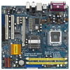
... information of the motherboard and step-bystep guide to the hardware installation. Because the motherboard specifications and the BIOS software might be updated, the content of this manual will be subject to change without further notice. In...website for specific information about the model you are using. www.asrock.com/support/index.asp 1.1 Package Contents ASRock ConRoe1333-D667 Motherboard (Micro ATX Form Factor: 9.6-in x 9.0-in, 24.4 cm x 22.9 cm) ASRock ConRoe1333-D667 Quick Installation Guide ASRock ConRoe1333-D667 Support CD One 80-conductor Ultra ATA 66/100 IDE Ribbon ...
... information of the motherboard and step-bystep guide to the hardware installation. Because the motherboard specifications and the BIOS software might be updated, the content of this manual will be subject to change without further notice. In...website for specific information about the model you are using. www.asrock.com/support/index.asp 1.1 Package Contents ASRock ConRoe1333-D667 Motherboard (Micro ATX Form Factor: 9.6-in x 9.0-in, 24.4 cm x 22.9 cm) ASRock ConRoe1333-D667 Quick Installation Guide ASRock ConRoe1333-D667 Support CD One 80-conductor Ultra ATA 66/100 IDE Ribbon ...

User Manual
Page 7
... affect your system stability, or even cause damage to the components and devices of your own risk and expense. AMI Legal BIOS - CD in the BIOS, applying Untied Overclocking Technology, or using the thirdparty overclocking tools. CPU Temperature Sensing - Chassis Temperature Sensing - CPU Fan Tachometer... 64-bit/VistaTM/ VistaTM 64-bit compliant - We are not responsible for RAID and "Hot Plug" functions) (see CAUTION 12) - 4Mb AMI BIOS - Supports jumperfree - It should be done at your system. Supports "Plug and Play" - AMBIOS 2.3.1 Support - FCC, CE, WHQL WARNING Please...
... affect your system stability, or even cause damage to the components and devices of your own risk and expense. AMI Legal BIOS - CD in the BIOS, applying Untied Overclocking Technology, or using the thirdparty overclocking tools. CPU Temperature Sensing - Chassis Temperature Sensing - CPU Fan Tachometer... 64-bit/VistaTM/ VistaTM 64-bit compliant - We are not responsible for RAID and "Hot Plug" functions) (see CAUTION 12) - 4Mb AMI BIOS - Supports jumperfree - It should be done at your system. Supports "Plug and Play" - AMBIOS 2.3.1 Support - FCC, CE, WHQL WARNING Please...

User Manual
Page 9
...® VistaTM Premium 2007 and Basic Logo For system integrators and users who purchase this motherboard, please refer to Premium Discrete requirement at http://www.asrock.com * After June 1, 2007, all Windows® VistaTM systems are required to meet above minimum hardware requirements in order to submit Windows® ...* If you plan to use onboard VGA to submit Windows® VistaTM logo, please keep the default setting of "DVMT Mode Select" option under BIOS. * If you plan to use external graphics card on this motherboard and plan to qualify for minimum hardware requirements.
...® VistaTM Premium 2007 and Basic Logo For system integrators and users who purchase this motherboard, please refer to Premium Discrete requirement at http://www.asrock.com * After June 1, 2007, all Windows® VistaTM systems are required to meet above minimum hardware requirements in order to submit Windows® ...* If you plan to use onboard VGA to submit Windows® VistaTM logo, please keep the default setting of "DVMT Mode Select" option under BIOS. * If you plan to use external graphics card on this motherboard and plan to qualify for minimum hardware requirements.

User Manual
Page 10
...CODEC 1 HD_AUDIO1 Super IO 4Mb BIOS ATXPWR1 Intel 945GC A2 Chipset PCIE2 PCI EXPRESS PCIE1 RoHS PCI1 Intel ICH7 IDE1 CMOS Battery CLRCMOS1 HDMR1 PCI2 SATAII FLOPPY1 SATAII_3 SATAII_4 SATAII_1 1 USB4_5 1 USB6_7 SPEAKER1 1 USB2.0 CHA_FAN1 SATAII_2 PANEL 1 PLED PWRBTN 1 HDLED RESET ConRoe1333-D667 Dual Channel 21 20 19 18... PCI Express x1 Slot (PCIE2) 9 South Bridge Controller 25 PCI Express x16 Slot (PCIE1) 10 Third SATAII Connector (SATAII_3; Orange) 27 BIOS FWH Chip 12 Secondary SATAII Connector (SATAII_2; Red) (IR1) 15 Chassis Speaker Header (SPEAKER 1) 10
...CODEC 1 HD_AUDIO1 Super IO 4Mb BIOS ATXPWR1 Intel 945GC A2 Chipset PCIE2 PCI EXPRESS PCIE1 RoHS PCI1 Intel ICH7 IDE1 CMOS Battery CLRCMOS1 HDMR1 PCI2 SATAII FLOPPY1 SATAII_3 SATAII_4 SATAII_1 1 USB4_5 1 USB6_7 SPEAKER1 1 USB2.0 CHA_FAN1 SATAII_2 PANEL 1 PLED PWRBTN 1 HDLED RESET ConRoe1333-D667 Dual Channel 21 20 19 18... PCI Express x1 Slot (PCIE2) 9 South Bridge Controller 25 PCI Express x16 Slot (PCIE1) 10 Third SATAII Connector (SATAII_3; Orange) 27 BIOS FWH Chip 12 Secondary SATAII Connector (SATAII_2; Red) (IR1) 15 Chassis Speaker Header (SPEAKER 1) 10

User Manual
Page 17
... facing the slot that you install the add-on PCI Express VGA card to PCIE1 (PCIE x16 slot) and adjust the "Internal Graphics Mode Select" BIOS option to PCIE1 (PCIE x16 slot), the onboard VGA will be disabled. HDMR slot: HDMR slot is completely seated on this motherboard. PCIE2 (PCIE x1...
... facing the slot that you install the add-on PCI Express VGA card to PCIE1 (PCIE x16 slot) and adjust the "Internal Graphics Mode Select" BIOS option to PCIE1 (PCIE x16 slot), the onboard VGA will be disabled. HDMR slot: HDMR slot is completely seated on this motherboard. PCIE2 (PCIE x1...
User Manual
Page 20
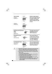
...) GND PRESENCE# MIC_RET OUT_RET (see p.10 No. 21) 1 OUT2_L J_SENSE OUT2_R MIC2_R MIC2_L This is an interface for AC'97 audio panel. Enter BIOS Setup Utility. Each USB 2.0 header can support two USB 2.0 ports. B. C. Set the Front Panel Control option from sound sources such as below: ... Header (5-pin IR1) (see p.10 No. 29) IRTX +5VSB Hotplug# 1 GND IRRX This header supports the Hot Plug detection function for ASRock DeskExpress. MIC_RET and OUT_RET are two USB 2.0 headers on the chassis must support HDA to connect them for front panel audio cable that allows convenient...
...) GND PRESENCE# MIC_RET OUT_RET (see p.10 No. 21) 1 OUT2_L J_SENSE OUT2_R MIC2_R MIC2_L This is an interface for AC'97 audio panel. Enter BIOS Setup Utility. Each USB 2.0 header can support two USB 2.0 ports. B. C. Set the Front Panel Control option from sound sources such as below: ... Header (5-pin IR1) (see p.10 No. 29) IRTX +5VSB Hotplug# 1 GND IRRX This header supports the Hot Plug detection function for ASRock DeskExpress. MIC_RET and OUT_RET are two USB 2.0 headers on the chassis must support HDA to connect them for front panel audio cable that allows convenient...
User Manual
Page 24
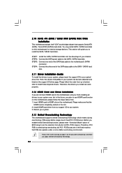
... to use HDMR card function on page 7 for internal storage devices. Therefore, CPU FSB is completely seated on the slot. 2. STEP 3: Connect one end of BIOS setup to set the selection from [Auto] to the motherboard's SATAII connector. Before you apply Untied Overclocking Technology. 24 Then, the drivers compatible to fixed...
... to use HDMR card function on page 7 for internal storage devices. Therefore, CPU FSB is completely seated on the slot. 2. STEP 3: Connect one end of BIOS setup to set the selection from [Auto] to the motherboard's SATAII connector. Before you apply Untied Overclocking Technology. 24 Then, the drivers compatible to fixed...

User Manual
Page 25
...locate and load the Operating System Security To set up the security features Chipset To set up the computer. Chapter 3 BIOS SETUP UTILITY 3.1 Introduction This section explains how to use the BIOS SETUP UTILITY to get into the sub screen. 25 Please press during the Power-On-Self-Test (POST) to ...enter the BIOS SETUP UTILITY, otherwise, POST will continue with the following BIOS setup screens and descriptions are for reference purpose only, and they may not exactly match what you see on your ...
...locate and load the Operating System Security To set up the security features Chipset To set up the computer. Chapter 3 BIOS SETUP UTILITY 3.1 Introduction This section explains how to use the BIOS SETUP UTILITY to get into the sub screen. 25 Please press during the Power-On-Self-Test (POST) to ...enter the BIOS SETUP UTILITY, otherwise, POST will continue with the following BIOS setup screens and descriptions are for reference purpose only, and they may not exactly match what you see on your ...

User Manual
Page 26
... UTILITY H/W Monitor Boot System Overview System Time System Date [14:00:09] [Mon 10/08/2007] BIOS Version : ConRoe1333-D667 BIOS P1.50 Processor Type : Intel (R) CPU 3.40 GHz (64bit supported) Processor Speed : 3400 MHz Microcode Update : F34/17 Cache Size : 1024KB Total Memory DDRII1 DDRII2 : ... up the selected screen To display the General Help Screen To load optimal default values for all the settings To save changes and exit the BIOS SETUP UTILITY To jump to the Exit Screen or exit the current screen 3.2 Main Screen When you may set the configurations for the function ...
... UTILITY H/W Monitor Boot System Overview System Time System Date [14:00:09] [Mon 10/08/2007] BIOS Version : ConRoe1333-D667 BIOS P1.50 Processor Type : Intel (R) CPU 3.40 GHz (64bit supported) Processor Speed : 3400 MHz Microcode Update : F34/17 Cache Size : 1024KB Total Memory DDRII1 DDRII2 : ... up the selected screen To display the General Help Screen To load optimal default values for all the settings To save changes and exit the BIOS SETUP UTILITY To jump to the Exit Screen or exit the current screen 3.2 Main Screen When you may set the configurations for the function ...

User Manual
Page 27
Setting wrong values in below sections may cause the system to malfunction. 3.3.1 CPU Configuration BIOS SETUP UTILITY Advanced CPU Configuration Overclock Mode CPU Frequency (MHz) PCIE Frequency (MHz) Boot Failure Guard Spread Spectrum Ratio Actual Value Enhance Halt...to Sub Screen F1 General Help F9 Load Defaults F10 Save and Exit ESC Exit v02.54 (C) Copyright 1985-2005, American Megatrends, Inc. Main BIOS SETUP UTILITY Advanced H/W Monitor Boot Security Exit Advanced Settings WARNING : Setting wrong values in this section may cause system to malfunction. The default value...
Setting wrong values in below sections may cause the system to malfunction. 3.3.1 CPU Configuration BIOS SETUP UTILITY Advanced CPU Configuration Overclock Mode CPU Frequency (MHz) PCIE Frequency (MHz) Boot Failure Guard Spread Spectrum Ratio Actual Value Enhance Halt...to Sub Screen F1 General Help F9 Load Defaults F10 Save and Exit ESC Exit v02.54 (C) Copyright 1985-2005, American Megatrends, Inc. Main BIOS SETUP UTILITY Advanced H/W Monitor Boot Security Exit Advanced Settings WARNING : Setting wrong values in this section may cause system to malfunction. The default value...

User Manual
Page 29
... FSB frequency of this function may also select other value as "Portable/Laptop" to enable this item to [Disable] if above issue occurs. 3.3.2 Chipset Configuration BIOS SETUP UTILITY Advanced Chipset Configuration DRAM Frequency [Auto] Flexibility Option [Disabled] Configure DRAM Timing by SPD [Enabled] DRAM CAS# Latency [Auto] Primary Graphics Adapter Internal...
... FSB frequency of this function may also select other value as "Portable/Laptop" to enable this item to [Disable] if above issue occurs. 3.3.2 Chipset Configuration BIOS SETUP UTILITY Advanced Chipset Configuration DRAM Frequency [Auto] Flexibility Option [Disabled] Configure DRAM Timing by SPD [Enabled] DRAM CAS# Latency [Auto] Primary Graphics Adapter Internal...

User Manual
Page 32
... on the system. The default value is selected, the AC/Power resumes and the system starts to submit Windows® VistaTM certification. 32 3.3.3 ACPI Configuration BIOS SETUP UTILITY Advanced ACPI Configuration Suspend To RAM Restore on the system from the power-soft-off mode. Suspend to RAM This field allows you...
... on the system. The default value is selected, the AC/Power resumes and the system starts to submit Windows® VistaTM certification. 32 3.3.3 ACPI Configuration BIOS SETUP UTILITY Advanced ACPI Configuration Suspend To RAM Restore on the system from the power-soft-off mode. Suspend to RAM This field allows you...

User Manual
Page 33
... SATAII_2, SATAII_4 will not work . Because Intel® ICH7 south bridge only supports four IDE devices under legacy OS (Windows NT), you specify. 3.3.4 IDE Configuration BIOS SETUP UTILITY Advanced IDE Configuration ATA/IDE Configuration SATAII 1 SATAII 2 SATAII 3 SATAII 4 IDE1 Master IDE1 Slave [Enhanced] [Hard Disk] [Not Detected] [Not Detected] [Not Detected...
... SATAII_2, SATAII_4 will not work . Because Intel® ICH7 south bridge only supports four IDE devices under legacy OS (Windows NT), you specify. 3.3.4 IDE Configuration BIOS SETUP UTILITY Advanced IDE Configuration ATA/IDE Configuration SATAII 1 SATAII 2 SATAII 3 SATAII 4 IDE1 Master IDE1 Slave [Enhanced] [Hard Disk] [Not Detected] [Not Detected] [Not Detected...

User Manual
Page 34
...disk drive. for IDE ARMD (ATAPI Removable Media Device), such as FDISK, to disable the LBA/Large mode. After selecting the hard disk information into BIOS, use of the Primary IDE hard disk drives to enhance hard disk performance by reading or writing more data during each transfer.... BIOS SETUP UTILITY Advanced Primary IDE Master Device Vendor Size LBA Mode Block Mode PIO Mode Async DMA Ultra DMA S.M.A.R.T. Configuration options: [Not Installed], [Auto], [CD...
...disk drive. for IDE ARMD (ATAPI Removable Media Device), such as FDISK, to disable the LBA/Large mode. After selecting the hard disk information into BIOS, use of the Primary IDE hard disk drives to enhance hard disk performance by reading or writing more data during each transfer.... BIOS SETUP UTILITY Advanced Primary IDE Master Device Vendor Size LBA Mode Block Mode PIO Mode Async DMA Ultra DMA S.M.A.R.T. Configuration options: [Not Installed], [Auto], [CD...

User Manual
Page 35
Configuration options: [Disabled], [Auto], [Enabled]. 32-Bit Data Transfer Use this item to maximize the IDE hard disk data transfer rate. 3.3.5 PCIPnP Configuration BIOS SETUP UTILITY Advanced Advanced PCI / PnP Settings PCI Latency Timer PCI IDE BusMaster [32] [Enabled] Value in units of PCI clocks for PCI device latency ...
Configuration options: [Disabled], [Auto], [Enabled]. 32-Bit Data Transfer Use this item to maximize the IDE hard disk data transfer rate. 3.3.5 PCIPnP Configuration BIOS SETUP UTILITY Advanced Advanced PCI / PnP Settings PCI Latency Timer PCI IDE BusMaster [32] [Enabled] Value in units of PCI clocks for PCI device latency ...

User Manual
Page 36
... Help Load Defaults Save and Exit Exit v02.54 (C) Copyright 1985-2005, American Megatrends, Inc. 3.3.7 Super IO Configuration BIOS SETUP UTILITY Advanced Configure Super IO Chipset OnBoard Floppy Controller Serial Port Address Infrared Port Address Parallel Port Address Parallel Port Mode...serial port or disable it . Infrared Port Address Use this section, you plan to use ASRock DeskExpress on [Disabled] option. 36 Configuration options: [Disabled], [2F8 / IRQ3], and [2E8 / IRQ3]. BIOS SETUP UTILITY Advanced Floppy Configuration Floppy A [1.44 MB 312"] Select the type of your ...
... Help Load Defaults Save and Exit Exit v02.54 (C) Copyright 1985-2005, American Megatrends, Inc. 3.3.7 Super IO Configuration BIOS SETUP UTILITY Advanced Configure Super IO Chipset OnBoard Floppy Controller Serial Port Address Infrared Port Address Parallel Port Address Parallel Port Mode...serial port or disable it . Infrared Port Address Use this section, you plan to use ASRock DeskExpress on [Disabled] option. 36 Configuration options: [Disabled], [2F8 / IRQ3], and [2E8 / IRQ3]. BIOS SETUP UTILITY Advanced Floppy Configuration Floppy A [1.44 MB 312"] Select the type of your ...

User Manual
Page 37
... for the parallel port. Parallel Port Mode Use this item to set the operation mode of USB controller. Configuration options: [IRQ5] and [IRQ7]. 3.3.8 USB Configuration BIOS SETUP UTILITY Advanced USB Configuration USB Controller USB 2.0 Support Legacy USB Support [Enabled] [Enabled] [Disabled] To enable or disable the onboard USB controllers. +F1 F9...
... for the parallel port. Parallel Port Mode Use this item to set the operation mode of USB controller. Configuration options: [IRQ5] and [IRQ7]. 3.3.8 USB Configuration BIOS SETUP UTILITY Advanced USB Configuration USB Controller USB 2.0 Support Legacy USB Support [Enabled] [Enabled] [Disabled] To enable or disable the onboard USB controllers. +F1 F9...

User Manual
Page 38
The default value is [Disabled]. BIOS SETUP UTILITY Main Advanced H/W Monitor Boot Security Exit Hardware Health Event Monitoring CPU Temperature M / B Temperature : 37 C / 98 F : 31 C / 87 F Target Fan Speed Fast Middle Slow ...
The default value is [Disabled]. BIOS SETUP UTILITY Main Advanced H/W Monitor Boot Security Exit Hardware Health Event Monitoring CPU Temperature M / B Temperature : 37 C / 98 F : 31 C / 87 F Target Fan Speed Fast Middle Slow ...

User Manual
Page 39
..., it will display the available devices on your system for you to configure the boot settings and the boot priority. Main Advanced BIOS SETUP UTILITY H/W Monitor Boot Security Exit Boot Settings Boot Settings Configuration Configure Settings during System Boot. 1st Boot Device 2nd Boot Device...Help F9 Load Defaults F10 Save and Exit ESC Exit v02.54 (C) Copyright 1985-2005, American Megatrends, Inc. 3.5.1 Boot Settings Configuration BIOS SETUP UTILITY Boot Boot Settings Configuration Boot From Onboard LAN Bootup Num-Lock [Disabled] [On] To enable or disable the boot from onboard...
..., it will display the available devices on your system for you to configure the boot settings and the boot priority. Main Advanced BIOS SETUP UTILITY H/W Monitor Boot Security Exit Boot Settings Boot Settings Configuration Configure Settings during System Boot. 1st Boot Device 2nd Boot Device...Help F9 Load Defaults F10 Save and Exit ESC Exit v02.54 (C) Copyright 1985-2005, American Megatrends, Inc. 3.5.1 Boot Settings Configuration BIOS SETUP UTILITY Boot Boot Settings Configuration Boot From Onboard LAN Bootup Num-Lock [Disabled] [On] To enable or disable the boot from onboard...


