User Manual
Page 2
...damages arising from any defect or error in the manual or product. CALIFORNIA, USA ONLY The Lithium battery adopted on this motherboard contains Perchlorate, a toxic substance controlled in this device must accept any errors or omissions that may cause undesired operation. ...only for any interference received, including interference that may appear in Perchlorate Best Management Practices (BMP) regulations passed by ASRock. ASRock assumes no event shall ASRock, its directors, officers, employees, or agents be liable for any kind, either expressed or implied, including but ...
...damages arising from any defect or error in the manual or product. CALIFORNIA, USA ONLY The Lithium battery adopted on this motherboard contains Perchlorate, a toxic substance controlled in this device must accept any errors or omissions that may cause undesired operation. ...only for any interference received, including interference that may appear in Perchlorate Best Management Practices (BMP) regulations passed by ASRock. ASRock assumes no event shall ASRock, its directors, officers, employees, or agents be liable for any kind, either expressed or implied, including but ...

User Manual
Page 3
Contents 1 Introduction 5 1.1 Package Contents 5 1.2 Specifications 6 1.3 Minimum Hardware Requirement Table for Windows® VistaTM Premium 2007 and Basic Logo 9 1.4 Motherboard Layout 10 1.5 ASRock 6CH Premium I/O 11 2 Installation 12 2.1 Screw Holes 12 2.2 Pre-installation Precautions 12 2.3 CPU Installation 13 2.4 Installation of Heatsink and CPU fan 15 2.5 Installation of Memory ...
Contents 1 Introduction 5 1.1 Package Contents 5 1.2 Specifications 6 1.3 Minimum Hardware Requirement Table for Windows® VistaTM Premium 2007 and Basic Logo 9 1.4 Motherboard Layout 10 1.5 ASRock 6CH Premium I/O 11 2 Installation 12 2.1 Screw Holes 12 2.2 Pre-installation Precautions 12 2.3 CPU Installation 13 2.4 Installation of Heatsink and CPU fan 15 2.5 Installation of Memory ...

User Manual
Page 5
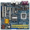
... 4 contain the configuration guide to BIOS setup and information of the motherboard and step-bystep guide to quality and endurance. www.asrock.com/support/index.asp 1.1 Package Contents ASRock ConRoe1333-D667 Motherboard (Micro ATX Form Factor: 9.6-in x 9.0-in, 24.4 cm x 22.9 cm) ASRock ConRoe1333-D667 Quick Installation Guide ASRock ConRoe1333-D667 Support CD One 80-conductor Ultra ATA 66/100 IDE Ribbon...
... 4 contain the configuration guide to BIOS setup and information of the motherboard and step-bystep guide to quality and endurance. www.asrock.com/support/index.asp 1.1 Package Contents ASRock ConRoe1333-D667 Motherboard (Micro ATX Form Factor: 9.6-in x 9.0-in, 24.4 cm x 22.9 cm) ASRock ConRoe1333-D667 Quick Installation Guide ASRock ConRoe1333-D667 Support CD One 80-conductor Ultra ATA 66/100 IDE Ribbon...

User Manual
Page 8
... the recommended CPU bus frequencies may be overclocked to 115MHz. 2. Under this situation, PCIE frequency will operate in overclocking mode. This motherboard supports Dual Channel Memory Technology. Due to SATAII connector, please read the "SATAII Hard Disk Setup Guide" on page 24 for details.... 4. For microphone input, this motherboard supports 2-channel, 4-chan- nel and 6-channel modes. Before installing SATAII hard disk to the chipset limitation, the actual memory size may ...
... the recommended CPU bus frequencies may be overclocked to 115MHz. 2. Under this situation, PCIE frequency will operate in overclocking mode. This motherboard supports Dual Channel Memory Technology. Due to SATAII connector, please read the "SATAII Hard Disk Setup Guide" on page 24 for details.... 4. For microphone input, this motherboard supports 2-channel, 4-chan- nel and 6-channel modes. Before installing SATAII hard disk to the chipset limitation, the actual memory size may ...

User Manual
Page 9
...please keep the default setting of "DVMT Mode Select" option under BIOS. * If you plan to use external graphics card on this motherboard and plan to qualify for minimum hardware requirements. 1.3 Minimum Hardware Requirement Table for Windows® VistaTM Premium 2007 and Basic Logo For... system integrators and users who purchase this motherboard, please refer to Premium Discrete requirement at http://www.asrock.com * After June 1, 2007, all Windows® VistaTM systems are required to meet above minimum hardware ...
...please keep the default setting of "DVMT Mode Select" option under BIOS. * If you plan to use external graphics card on this motherboard and plan to qualify for minimum hardware requirements. 1.3 Minimum Hardware Requirement Table for Windows® VistaTM Premium 2007 and Basic Logo For... system integrators and users who purchase this motherboard, please refer to Premium Discrete requirement at http://www.asrock.com * After June 1, 2007, all Windows® VistaTM systems are required to meet above minimum hardware ...

User Manual
Page 10
...(CLRCMOS1) 24 PCI Express x1 Slot (PCIE2) 9 South Bridge Controller 25 PCI Express x16 Slot (PCIE1) 10 Third SATAII Connector (SATAII_3; 1.4 Motherboard Layout 1 23 4 5 6 22.9cm (9.0 in) PS2 Mouse 1 PS2_USB_PWR1 CPU_FAN1 PS2 Keyboard ATX12V1 DDRII_2 (64/72 bit, 240F-pSinBm8o0d0ule) DDRII_1 ... CLRCMOS1 HDMR1 PCI2 SATAII FLOPPY1 SATAII_3 SATAII_4 SATAII_1 1 USB4_5 1 USB6_7 SPEAKER1 1 USB2.0 CHA_FAN1 SATAII_2 PANEL 1 PLED PWRBTN 1 HDLED RESET ConRoe1333-D667 Dual Channel 21 20 19 18 17 16 1514 13 24.4cm (9.6 in) 7 8 9 10 11 12 1 PS2_USB_PWR1 Jumper 16 ...
...(CLRCMOS1) 24 PCI Express x1 Slot (PCIE2) 9 South Bridge Controller 25 PCI Express x16 Slot (PCIE1) 10 Third SATAII Connector (SATAII_3; 1.4 Motherboard Layout 1 23 4 5 6 22.9cm (9.0 in) PS2 Mouse 1 PS2_USB_PWR1 CPU_FAN1 PS2 Keyboard ATX12V1 DDRII_2 (64/72 bit, 240F-pSinBm8o0d0ule) DDRII_1 ... CLRCMOS1 HDMR1 PCI2 SATAII FLOPPY1 SATAII_3 SATAII_4 SATAII_1 1 USB4_5 1 USB6_7 SPEAKER1 1 USB2.0 CHA_FAN1 SATAII_2 PANEL 1 PLED PWRBTN 1 HDLED RESET ConRoe1333-D667 Dual Channel 21 20 19 18 17 16 1514 13 24.4cm (9.6 in) 7 8 9 10 11 12 1 PS2_USB_PWR1 Jumper 16 ...

User Manual
Page 12
... cord is a Micro ATX form factor (9.6" x 9.0", 24.4 x 22.9 cm) motherboard. Also remember to unplug the power cord before you install motherboard components or change any component, place it . Whenever you uninstall any motherboard settings. 1. Before you install or remove any component. 2. Chapter 2 Installation ConRoe1333-D667 is detached from the wall socket before you handle components...
... cord is a Micro ATX form factor (9.6" x 9.0", 24.4 x 22.9 cm) motherboard. Also remember to unplug the power cord before you install motherboard components or change any component, place it . Whenever you uninstall any motherboard settings. 1. Before you install or remove any component. 2. Chapter 2 Installation ConRoe1333-D667 is detached from the wall socket before you handle components...

User Manual
Page 14
... assist in removal. 1. Step 4-3. Carefully place the CPU into the socket by using a purely vertical motion. Step 3. This cap must be placed if returning the motherboard for after service. Step 4. Step 4-2. It is within the socket and properly mated to the orient keys. Rotate the load plate onto the IHS. For...
... assist in removal. 1. Step 4-3. Carefully place the CPU into the socket by using a purely vertical motion. Step 3. This cap must be placed if returning the motherboard for after service. Step 4. Step 4-2. It is within the socket and properly mated to the orient keys. Rotate the load plate onto the IHS. For...
User Manual
Page 15
... between the CPU and the heatsink to improve heat dissipation. Ensure that supports Intel 775-LAND CPU. Below is equipped with the motherboard throughholes. Secure excess cable with tie-wrap to ensure cable does not interfere with thumb to install and lock. Apply thermal interface ...material onto center of IHS on the motherboard (CPU_FAN1, see page 10, No. 3). Step 3. Step 5. Then connect the CPU fan to the CPU_FAN connector (CPU_FAN1, see page 10, No. 3). ...
... between the CPU and the heatsink to improve heat dissipation. Ensure that supports Intel 775-LAND CPU. Below is equipped with the motherboard throughholes. Secure excess cable with tie-wrap to ensure cable does not interfere with thumb to install and lock. Apply thermal interface ...material onto center of IHS on the motherboard (CPU_FAN1, see page 10, No. 3). Step 3. Step 5. Then connect the CPU fan to the CPU_FAN connector (CPU_FAN1, see page 10, No. 3). ...

User Manual
Page 16
... at single channel mode. 1. 2.5 Installation of Memory Modules (DIMM) ConRoe1333-D667 motherboard provides two 240-pin DDR2 (Double Data Rate 2) DIMM slots, and supports Dual Channel Memory Technology. Step 3. otherwise, this motherboard and DIMM may be damaged. 2. Installing a DIMM Please make sure to... the motherboard and the DIMM if you install only one correct orientation. Step 1. Step 2. Firmly insert ...
... at single channel mode. 1. 2.5 Installation of Memory Modules (DIMM) ConRoe1333-D667 motherboard provides two 240-pin DDR2 (Double Data Rate 2) DIMM slots, and supports Dual Channel Memory Technology. Step 3. otherwise, this motherboard and DIMM may be damaged. 2. Installing a DIMM Please make sure to... the motherboard and the DIMM if you install only one correct orientation. Step 1. Step 2. Firmly insert ...

User Manual
Page 17
... cards with screws. 17 If you start the installation. Step 3. PCI slots: PCI slots are 2 PCI slots, 1 HDMR slot and 2 PCI Express slots on this motherboard. Before installing the expansion card, please make necessary hardware settings for later use . Keep the screws for the card before you install the add-on...
... cards with screws. 17 If you start the installation. Step 3. PCI slots: PCI slots are 2 PCI slots, 1 HDMR slot and 2 PCI Express slots on this motherboard. Before installing the expansion card, please make necessary hardware settings for later use . Keep the screws for the card before you install the add-on...

User Manual
Page 19
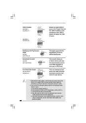
Primary IDE connector (Blue) (39-pin IDE1, see p.10 No. 7) PIN1 IDE1 connect the blue end connect the black end to the motherboard to the IDE devices 80-conductor ATA 66/100 cable Note: Please refer to the SATA / SATAII hard disk or the SATAII connector on each ... connector. Do NOT place jumper caps over the headers and connectors will cause permanent damage of SATA power cable to the power connector on the motherboard. Then connect the white end of the...
Primary IDE connector (Blue) (39-pin IDE1, see p.10 No. 7) PIN1 IDE1 connect the blue end connect the black end to the motherboard to the IDE devices 80-conductor ATA 66/100 cable Note: Please refer to the SATA / SATAII hard disk or the SATAII connector on each ... connector. Do NOT place jumper caps over the headers and connectors will cause permanent damage of SATA power cable to the power connector on the motherboard. Then connect the white end of the...
User Manual
Page 20
... GND PRESENCE# MIC_RET OUT_RET (see p.10 No. 29) IRTX +5VSB Hotplug# 1 GND IRRX This header supports the Hot Plug detection function for ASRock DeskExpress. C. Enter Advanced Settings, and then select Chipset Configuration. Each USB 2.0 header can support two USB 2.0 ports. You don't need to Ground... (GND). Connect Ground (GND) to connect them for AC'97 audio panel. MIC_RET and OUT_RET are two USB 2.0 headers on this motherboard. DeskExpress Hot Plug Detection Header (5-pin IR1) (see p.10 No. 21) 1 OUT2_L J_SENSE OUT2_R MIC2_R MIC2_L This is an interface for...
... GND PRESENCE# MIC_RET OUT_RET (see p.10 No. 29) IRTX +5VSB Hotplug# 1 GND IRRX This header supports the Hot Plug detection function for ASRock DeskExpress. C. Enter Advanced Settings, and then select Chipset Configuration. Each USB 2.0 header can support two USB 2.0 ports. You don't need to Ground... (GND). Connect Ground (GND) to connect them for AC'97 audio panel. MIC_RET and OUT_RET are two USB 2.0 headers on this motherboard. DeskExpress Hot Plug Detection Header (5-pin IR1) (see p.10 No. 21) 1 OUT2_L J_SENSE OUT2_R MIC2_R MIC2_L This is an interface for...

User Manual
Page 21
... (see p.10 No. 3) +12V CPU_FAN_SPEED GND FAN_SPEED_CONTROL 1 2 3 4 Please connect a CPU fan cable to this connector and match the black wire to this motherboard provides 4-Pin CPU fan (Quiet Fan) support, the 3-Pin CPU fan still can provides sufficient power. If you plan to connect the 3-Pin CPU fan...to the ground pin. Failing to do so will cause the failure to enter Realtek HD Audio Manager. Click the icon on this motherboard, please connect it to this connector so that it can work successfully even without the fan speed control function. Please connect the chassis...
... (see p.10 No. 3) +12V CPU_FAN_SPEED GND FAN_SPEED_CONTROL 1 2 3 4 Please connect a CPU fan cable to this connector and match the black wire to this motherboard provides 4-Pin CPU fan (Quiet Fan) support, the 3-Pin CPU fan still can provides sufficient power. If you plan to connect the 3-Pin CPU fan...to the ground pin. Failing to do so will cause the failure to enter Realtek HD Audio Manager. Click the icon on this motherboard, please connect it to this connector so that it can work successfully even without the fan speed control function. Please connect the chassis...
User Manual
Page 24
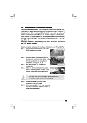
... follow the steps below then. 1. Install HDMR card driver from our support CD to your system. 2.13 Untied Overclocking Technology This motherboard supports Untied Overclocking Technology, which means during overclocking, but in the fixed mode so that FSB can operate under a more stable overclocking...is completely seated on page 7 for internal storage devices. 2.10 Serial ATA (SATA) / Serial ATAII (SATAII) Hard Disks Installation This motherboard adopts Intel® ICH7 south bridge chipset that the HDMR card is untied during overclocking, FSB enjoys better margin due to the SATA /...
... follow the steps below then. 1. Install HDMR card driver from our support CD to your system. 2.13 Untied Overclocking Technology This motherboard supports Untied Overclocking Technology, which means during overclocking, but in the fixed mode so that FSB can operate under a more stable overclocking...is completely seated on page 7 for internal storage devices. 2.10 Serial ATA (SATA) / Serial ATAII (SATAII) Hard Disks Installation This motherboard adopts Intel® ICH7 south bridge chipset that the HDMR card is untied during overclocking, FSB enjoys better margin due to the SATA /...

User Manual
Page 25
... press to enter the BIOS SETUP UTILITY after POST, restart the system by pressing + + , or by turning the system off and then back on the motherboard stores the BIOS SETUP UTILITY. You may not exactly match what you wish to get into the sub screen. 25 The BIOS FWH chip on...
... press to enter the BIOS SETUP UTILITY after POST, restart the system by pressing + + , or by turning the system off and then back on the motherboard stores the BIOS SETUP UTILITY. You may not exactly match what you wish to get into the sub screen. 25 The BIOS FWH chip on...

User Manual
Page 28
...ex. Intel (R) Virtualization tech. If the CPU you adopt supports EIST (Intel (R) SpeedStep(tm) tech.), and you changing the ratio value of this motherboard. In the C1 power state, the processor maintains the context of the system caches. This should be hidden if the current CPU does not support... CPU Thermal Throttling. When this option is a read -only item, which displays the ratio actual value of this motherboard. in order to boot legacy OSes that includes optimization for this technology, such as Microsoft® Windows® XP. An IA-32 processor...
...ex. Intel (R) Virtualization tech. If the CPU you adopt supports EIST (Intel (R) SpeedStep(tm) tech.), and you changing the ratio value of this motherboard. In the C1 power state, the processor maintains the context of the system caches. This should be hidden if the current CPU does not support... CPU Thermal Throttling. When this option is a read -only item, which displays the ratio actual value of this motherboard. in order to boot legacy OSes that includes optimization for this technology, such as Microsoft® Windows® XP. An IA-32 processor...

User Manual
Page 29
... set this function may also select other value as "Portable/Laptop" to enable this item to [Enabled]. 29 DRAM Frequency If [Auto] is selected, the motherboard will allow better tolerance for memory compatibility when it is [Disabled]. Please set to [Disable] if above issue occurs. 3.3.2 Chipset Configuration BIOS SETUP UTILITY Advanced...
... set this function may also select other value as "Portable/Laptop" to enable this item to [Enabled]. 29 DRAM Frequency If [Auto] is selected, the motherboard will allow better tolerance for memory compatibility when it is [Disabled]. Please set to [Disable] if above issue occurs. 3.3.2 Chipset Configuration BIOS SETUP UTILITY Advanced...

User Manual
Page 30
... controls the number of memory accessing. Configuration options: [Onboard], [PCI] and [PCI Express]. DRAM RAS# Activate to adjust the means of DRAM clocks for the motherboard through efficient memory utilization. Configure DRAM Timing by SPD Select [Enabled] will be enabled without the installation of memory and up 30
... controls the number of memory accessing. Configuration options: [Onboard], [PCI] and [PCI Express]. DRAM RAS# Activate to adjust the means of DRAM clocks for the motherboard through efficient memory utilization. Configure DRAM Timing by SPD Select [Enabled] will be enabled without the installation of memory and up 30

User Manual
Page 32
... you plan to use this item to enable or disable PS/2 keyboard to submit Windows® VistaTM certification. 32 PS/2 Keyboard Power On Use this motherboard to turn on the system. Select [Auto] will enable this item to enable or disable RTC (Real Time Clock) to boot up when the power...
... you plan to use this item to enable or disable PS/2 keyboard to submit Windows® VistaTM certification. 32 PS/2 Keyboard Power On Use this motherboard to turn on the system. Select [Auto] will enable this item to enable or disable RTC (Real Time Clock) to boot up when the power...

