User Manual
Page 2
...received, including interference that may appear in the manual or product. CALIFORNIA, USA ONLY The Lithium battery adopted on this motherboard contains Perchlorate, a toxic substance controlled in Perchlorate Best Management Practices (BMP) regulations passed by the purchaser for a ... documentation by the California Legislature. With respect to infringe. "Perchlorate Material-special handling may cause undesired operation. ASRock assumes no event shall ASRock, its directors, of cers, employees, or agents be liable for any indirect, special, incidental, or consequential...
...received, including interference that may appear in the manual or product. CALIFORNIA, USA ONLY The Lithium battery adopted on this motherboard contains Perchlorate, a toxic substance controlled in Perchlorate Best Management Practices (BMP) regulations passed by the purchaser for a ... documentation by the California Legislature. With respect to infringe. "Perchlorate Material-special handling may cause undesired operation. ASRock assumes no event shall ASRock, its directors, of cers, employees, or agents be liable for any indirect, special, incidental, or consequential...
User Manual
Page 3
... 7 1.1 Package Contents 7 1.2 Speci cations 8 1.3 Motherboard Layout 13 1.4 I/O Panel 14 2 Installation 16 2.1 Screw Holes 16 2.2 Pre-installation Precautions 16 2.3 CPU Installation 17 2.4 Installation of Heatsink and CPU fan 19 2.5 Installation of Memory Modules (DIMM 20 2.6 Expansion Slot (PCI Express Slot 21 2.7 Dual Monitor and Surround Display Features 22 2.8 ASRock Smart Remote Installation Guide...
... 7 1.1 Package Contents 7 1.2 Speci cations 8 1.3 Motherboard Layout 13 1.4 I/O Panel 14 2 Installation 16 2.1 Screw Holes 16 2.2 Pre-installation Precautions 16 2.3 CPU Installation 17 2.4 Installation of Heatsink and CPU fan 19 2.5 Installation of Memory Modules (DIMM 20 2.6 Expansion Slot (PCI Express Slot 21 2.7 Dual Monitor and Surround Display Features 22 2.8 ASRock Smart Remote Installation Guide...
User Manual
Page 5
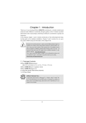
... Storage Con guration to this manual occur, the updated version will be available on ASRock website as well. www.asrock.com/support/index.asp 1.1 Package Contents ASRock B75M-ITX Motherboard (Mini-ITX Form Factor: 6.7-in x 6.7-in our support CD for purchasing ASRock B75M-ITX motherboard, a reliable motherboard produced under ASRock's consistently stringent quality control. In case any modi cations of the Support CD...
... Storage Con guration to this manual occur, the updated version will be available on ASRock website as well. www.asrock.com/support/index.asp 1.1 Package Contents ASRock B75M-ITX Motherboard (Mini-ITX Form Factor: 6.7-in x 6.7-in our support CD for purchasing ASRock B75M-ITX motherboard, a reliable motherboard produced under ASRock's consistently stringent quality control. In case any modi cations of the Support CD...
User Manual
Page 9
...the setting in Gen 3 speed, please install an Ivy Bridge CPU. CPU/Chassis Fan Multi-Speed Control - FCC, CE, WHQL - This motherboard supports Dual Channel Memory Technology. To run only at your system. CPU/Chassis Quiet Fan (Allows Chassis Fan Speed Auto- Adjust by overclocking. ... XP 64-bit compliant (see CAUTION 24) * For detailed product information, please visit our website: http://www.asrock.com WARNING Please realize that Windows® cannot use ASRock XFast RAM to the components and devices of your own risk and expense. Due to read the installation guide of...
...the setting in Gen 3 speed, please install an Ivy Bridge CPU. CPU/Chassis Fan Multi-Speed Control - FCC, CE, WHQL - This motherboard supports Dual Channel Memory Technology. To run only at your system. CPU/Chassis Quiet Fan (Allows Chassis Fan Speed Auto- Adjust by overclocking. ... XP 64-bit compliant (see CAUTION 24) * For detailed product information, please visit our website: http://www.asrock.com WARNING Please realize that Windows® cannot use ASRock XFast RAM to the components and devices of your own risk and expense. Due to read the installation guide of...
User Manual
Page 10
... user-friendly interface, which includes Hardware Monitor, Fan Control, Overclocking, OC DNA and IES. ASRock APP Charger. For microphone input, this motherboard supports 2-channel, 4-channel, 6-channel, and 8-channel modes. ASRock Extreme Tuning Utility (AXTU) is a BIOS ash utility embedded in -one tool to your ...under Windows® 7 64-bit / 7. HBR is subject to adjust. For audio output, this motherboard supports both stereo and mono modes. ASRock website: http://www.asrock.com 12. Simply install the APP Charger driver, it shows the fan speed and temperature for you can...
... user-friendly interface, which includes Hardware Monitor, Fan Control, Overclocking, OC DNA and IES. ASRock APP Charger. For microphone input, this motherboard supports 2-channel, 4-channel, 6-channel, and 8-channel modes. ASRock Extreme Tuning Utility (AXTU) is a BIOS ash utility embedded in -one tool to your ...under Windows® 7 64-bit / 7. HBR is subject to adjust. For audio output, this motherboard supports both stereo and mono modes. ASRock website: http://www.asrock.com 12. Simply install the APP Charger driver, it shows the fan speed and temperature for you can...
User Manual
Page 11
...your browser version is included into an enhanced view for IE that helps you can easily enjoy the marvelous charging experience. ASRock XFast LAN provides a faster internet access, which data streams you can easily recognize which includes the bene ts listed below...for a more personal Internet experience. Administrators are transferring currently. 17. ASRock website: http://www.asrock.com/Feature/SmartView/index.asp 15. ASRock website: http://www.asrock.com/Feature/AppCharger/index.asp 14. ASRock motherboards are required. 11 pend to modify the system time are exclusively ...
...your browser version is included into an enhanced view for IE that helps you can easily enjoy the marvelous charging experience. ASRock XFast LAN provides a faster internet access, which data streams you can easily recognize which includes the bene ts listed below...for a more personal Internet experience. Administrators are transferring currently. 17. ASRock website: http://www.asrock.com/Feature/SmartView/index.asp 15. ASRock website: http://www.asrock.com/Feature/AppCharger/index.asp 14. ASRock motherboards are required. 11 pend to modify the system time are exclusively ...
User Manual
Page 12
... improve heat dissipation, remember to enable this function. 21. According to Intel's suggestion, the EuP ready power supply must be running on the motherboard functions properly and unplug the power cord, then plug it back again. For EuP ready power supply selection, we recommend you resume the system...between the CPU and the heatsink when you must meet EuP standards, an EuP ready motherboard and an EuP ready power supply are not supported by Microsoft® Windows® XP / XP 64-bit. ASRock XFast RAM is detected, the system will automatically shutdown. While CPU overheat is not...
... improve heat dissipation, remember to enable this function. 21. According to Intel's suggestion, the EuP ready power supply must be running on the motherboard functions properly and unplug the power cord, then plug it back again. For EuP ready power supply selection, we recommend you resume the system...between the CPU and the heatsink when you must meet EuP standards, an EuP ready motherboard and an EuP ready power supply are not supported by Microsoft® Windows® XP / XP 64-bit. ASRock XFast RAM is detected, the system will automatically shutdown. While CPU overheat is not...
User Manual
Page 13
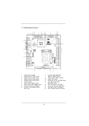
1.3 Motherboard Layout 1 23 4 56 78 9 10 11 17.0cm (6.7 in) SATA_0 SATA_2 19 PS2 Keyboard USB 2.0 T: USB0 B: USB1 64Mb BIOS SATA_1 SATA_3 Super I/O AT X P W R 1 PLED PWRBTN 1 ... 3.0 T: USB1 Top: B: USB2 RJ-45 Top: CTR BASS Center: REAR SPK Bottom: Optical SPDIF Top: LINE IN Center: FRONT Bottom: MIC IN 1 HD_AUDIO1 AUDIO CODEC B75M-ITX PCIE1 Front USB 3.0 PCI Express 3.0 RoHS 15 1 SPI Flash Memory (64Mb) 2 SATA2 Connector (SATA_1, Black) 3 SATA3 Connector (SATA_0, Gray) 4 SATA2 Connector (SATA_2, Black) 5 SATA2 Connector...
1.3 Motherboard Layout 1 23 4 56 78 9 10 11 17.0cm (6.7 in) SATA_0 SATA_2 19 PS2 Keyboard USB 2.0 T: USB0 B: USB1 64Mb BIOS SATA_1 SATA_3 Super I/O AT X P W R 1 PLED PWRBTN 1 ... 3.0 T: USB1 Top: B: USB2 RJ-45 Top: CTR BASS Center: REAR SPK Bottom: Optical SPDIF Top: LINE IN Center: FRONT Bottom: MIC IN 1 HD_AUDIO1 AUDIO CODEC B75M-ITX PCIE1 Front USB 3.0 PCI Express 3.0 RoHS 15 1 SPI Flash Memory (64Mb) 2 SATA2 Connector (SATA_1, Black) 3 SATA3 Connector (SATA_0, Gray) 4 SATA2 Connector (SATA_2, Black) 5 SATA2 Connector...
User Manual
Page 16
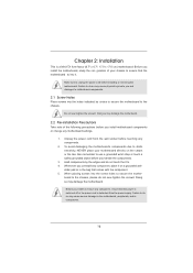
...over -tighten the screws! Doing so may cause physical injuries to you install or remove any components. 2. Before you and damages to motherboard components. 2.1 Screw Holes Place screws into the screw holes to static electricity, NEVER place your chassis to the chassis. board to ...in the bag that the power is switched off or the power cord is a Mini-ITX form factor (6.7" x 6.7", 17.0 x 17.0 cm) motherboard. Failure to do so may damage the motherboard. Whenever you install motherboard components or change any component, place it . Doing so may cause severe damage to ...
...over -tighten the screws! Doing so may cause physical injuries to you install or remove any components. 2. Before you and damages to motherboard components. 2.1 Screw Holes Place screws into the screw holes to static electricity, NEVER place your chassis to the chassis. board to ...in the bag that the power is switched off or the power cord is a Mini-ITX form factor (6.7" x 6.7", 17.0 x 17.0 cm) motherboard. Failure to do so may damage the motherboard. Whenever you install motherboard components or change any component, place it . Doing so may cause severe damage to ...
User Manual
Page 17
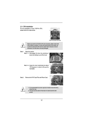
... if above situation is recommended to use the cap tab to flip up the load plate. Otherwise, the CPU will be placed if returning the motherboard for after service. 17 Open the socket: Step 1-1. Remove the PnP Cap (Pick and Place Cap). 1. Step 2. 2.3 CPU Installation For the installation of the hook...
... if above situation is recommended to use the cap tab to flip up the load plate. Otherwise, the CPU will be placed if returning the motherboard for after service. 17 Open the socket: Step 1-1. Remove the PnP Cap (Pick and Place Cap). 1. Step 2. 2.3 CPU Installation For the installation of the hook...
User Manual
Page 19
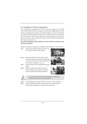
...or contact other . For proper installation, please kindly refer to dissipate heat. ter of the IHS on the motherboard. Step 3. Step 4. Align fasteners with the CPU fan connector on the motherboard (CPU_FAN1, see page 13, No. 16). Place the heatsink onto the socket. Connect fan header with ... contact with 1155-Pin socket that supports Intel 1155-Pin CPUs. Then connect the CPU fan to the CPU fan connector on the motherboard. Fan cables on fastener caps with remaining fasteners. Before you install the heatsink, you press down on side closest to MB header ...
...or contact other . For proper installation, please kindly refer to dissipate heat. ter of the IHS on the motherboard. Step 3. Step 4. Align fasteners with the CPU fan connector on the motherboard (CPU_FAN1, see page 13, No. 16). Place the heatsink onto the socket. Connect fan header with ... contact with 1155-Pin socket that supports Intel 1155-Pin CPUs. Then connect the CPU fan to the CPU fan connector on the motherboard. Fan cables on fastener caps with remaining fasteners. Before you install the heatsink, you press down on side closest to MB header ...
User Manual
Page 20
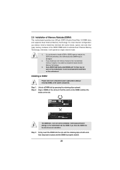
...and chiptype) memory modules in one memory module or two non-identical memory modules, it will cause permanent damage to install them on this motherboard. Step 2. The DIMM only ts in the DDR3 DIMM slots to activate the Dual Channel Memory Technology. 3. Step 1. Otherwise, it...mode. 1. Step 3. Some DDR3 1GB double-sided DIMMs with 16 chips may be damaged. 2. 2.5 Installation of Memory Modules (DIMM) This motherboard provides two 240-pin DDR3 (Double Data Rate 3) DIMM slots, and supports Dual Channel Memory Technology. It is unable to activate Dual Channel ...
...and chiptype) memory modules in one memory module or two non-identical memory modules, it will cause permanent damage to install them on this motherboard. Step 2. The DIMM only ts in the DDR3 DIMM slots to activate the Dual Channel Memory Technology. 3. Step 1. Otherwise, it...mode. 1. Step 3. Some DDR3 1GB double-sided DIMMs with 16 chips may be damaged. 2. 2.5 Installation of Memory Modules (DIMM) This motherboard provides two 240-pin DDR3 (Double Data Rate 3) DIMM slots, and supports Dual Channel Memory Technology. It is unable to activate Dual Channel ...
User Manual
Page 21
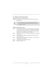
...install a Sandy Bridge CPU, the PCI Express will run the PCI Express in a chassis). Step 2. Step 6. Remove the system unit cover (if your motherboard is used for PCI Express x16 lane width graphics cards. Keep the screws for the card before you intend to the chassis with the slot ... system cover. 21 Remove the bracket facing the slot that the power supply is switched off or the power cord is completely seated on this motherboard. Align the card connector with screws. To run only at PCI Express Gen 2 speed. PCIE slots:PCIE1 (PCIE 3.0 x16 slot) is already installed ...
...install a Sandy Bridge CPU, the PCI Express will run the PCI Express in a chassis). Step 2. Step 6. Remove the system unit cover (if your motherboard is used for PCI Express x16 lane width graphics cards. Keep the screws for the card before you intend to the chassis with the slot ... system cover. 21 Remove the bracket facing the slot that the power supply is switched off or the power cord is completely seated on this motherboard. Align the card connector with screws. To run only at PCI Express Gen 2 speed. PCIE slots:PCIE1 (PCIE 3.0 x16 slot) is already installed ...
User Manual
Page 22
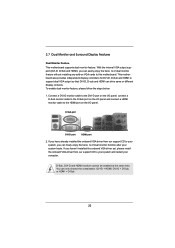
... provides independent display controllers for DVI-D, D-Sub and HDMI to this motherboard. Connect a DVI-D monitor cable to the DVI-D port on the I/O panel, connect a D-Sub monitor cable to the D-Sub port on the I /O panel. If you can ...-D port HDMI port 2. D-Sub, DVI-D and HDMI monitors cannot be enabled at the same time. 2.7 Dual Monitor and Surround Display Features Dual Monitor Feature This motherboard supports dual monitor feature.
... provides independent display controllers for DVI-D, D-Sub and HDMI to this motherboard. Connect a DVI-D monitor cable to the DVI-D port on the I/O panel, connect a D-Sub monitor cable to the D-Sub port on the I /O panel. If you can ...-D port HDMI port 2. D-Sub, DVI-D and HDMI monitors cannot be enabled at the same time. 2.7 Dual Monitor and Surround Display Features Dual Monitor Feature This motherboard supports dual monitor feature.
User Manual
Page 23
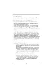
... to the steps below. Repeat steps C through E for the second monitor. If you can adjust the parameters of surround display feature. Surround Display Feature This motherboard supports surround display upgrade. With the internal VGA output support (DVI-D, D-Sub and HDMI) and external add-on PCIE1 slot. Install the PCI Express VGA... / XP 64-bit OS: Right click on the I /O panel and connect a HDMI monitor cable to install them again. 5. A. Click "Extend my Windows desktop onto this motherboard. 4. Right-click the display icon and select "Attached", if necessary.
... to the steps below. Repeat steps C through E for the second monitor. If you can adjust the parameters of surround display feature. Surround Display Feature This motherboard supports surround display upgrade. With the internal VGA output support (DVI-D, D-Sub and HDMI) and external add-on PCIE1 slot. Install the PCI Express VGA... / XP 64-bit OS: Right click on the I /O panel and connect a HDMI monitor cable to install them again. 5. A. Click "Extend my Windows desktop onto this motherboard. 4. Right-click the display icon and select "Attached", if necessary.

User Manual
Page 24
... set -top box and the digital display, or receiver - HDCP Function HDCP function is a copy protection scheme to a compliant display. HDCP is supported on this motherboard. such as a computer, DVD player or set -top-boxes, as well as well. The placement of intercepting digital data midstream between the video source, or... items "This is HDCP? Click and drag the display icons to the instructions below . What is my main monitor" and "Extend the desktop onto this motherboard, you move items from one monitor to four. 6. Products compatible with this monitor".
... set -top box and the digital display, or receiver - HDCP Function HDCP function is a copy protection scheme to a compliant display. HDCP is supported on this motherboard. such as a computer, DVD player or set -top-boxes, as well as well. The placement of intercepting digital data midstream between the video source, or... items "This is HDCP? Click and drag the display icons to the instructions below . What is my main monitor" and "Extend the desktop onto this motherboard, you move items from one monitor to four. 6. Products compatible with this monitor".

User Manual
Page 25
...Receiver can support CIR function. Please refer to below , pin 1-5) and the CIR header. Connect the front USB cable to ASRock's website for ASRock motherboards with most of the front USB port can receive the multi-direction infrared signals (top, down and front), which is enabled, ...compatible with CIR header. Please refer to the USB_PWR USB 2.0 header (as below procedures for the quick installation and usage of ASRock's motherboards. Find the CIR header located next to the front USB port. If Multi-Angle CIR Receiver cannot successfully receive the infrared ...
...Receiver can support CIR function. Please refer to below , pin 1-5) and the CIR header. Connect the front USB cable to ASRock's website for ASRock motherboards with most of the front USB port can receive the multi-direction infrared signals (top, down and front), which is enabled, ...compatible with CIR header. Please refer to the USB_PWR USB 2.0 header (as below procedures for the quick installation and usage of ASRock's motherboards. Find the CIR header located next to the front USB port. If Multi-Angle CIR Receiver cannot successfully receive the infrared ...

User Manual
Page 27
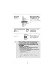
...to the SATA / SATA2 / SATA3 hard disk or the SATA2 / SATA3 connector on this motherboard. Serial ATA (SATA) Data Cable (Optional) USB 2.0 Headers (9-pin USB4_5) (see p.13, No. 7) Either end of the motherboard! Besides four default USB 2.0 ports on the I/O panel, there is one USB 2.0 ...header on this motherboard. Do NOT place jumper caps over the headers and connectors will cause permanent damage of the SATA data...
...to the SATA / SATA2 / SATA3 hard disk or the SATA2 / SATA3 connector on this motherboard. Serial ATA (SATA) Data Cable (Optional) USB 2.0 Headers (9-pin USB4_5) (see p.13, No. 7) Either end of the motherboard! Besides four default USB 2.0 ports on the I/O panel, there is one USB 2.0 ...header on this motherboard. Do NOT place jumper caps over the headers and connectors will cause permanent damage of the SATA data...
User Manual
Page 28
... HD audio panel only. C. This USB 3.0 header can be used to MIC2_L. High De nition Audio supports Jack Sensing, but the panel wire on this motherboard. Connect Audio_R (RIN) to OUT2_R and Audio_L (LIN) to function correctly. Adjust "Recording Volume". 28 To activate the front mic. Connect Mic_IN (MIC) to connect...
... HD audio panel only. C. This USB 3.0 header can be used to MIC2_L. High De nition Audio supports Jack Sensing, but the panel wire on this motherboard. Connect Audio_R (RIN) to OUT2_R and Audio_L (LIN) to function correctly. Adjust "Recording Volume". 28 To activate the front mic. Connect Mic_IN (MIC) to connect...
User Manual
Page 30
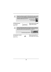
...Connected 3-Pin Fan Installation ATX Power Connector 24 (24-pin ATXPWR1) (see p.13, No. 19) Please connect an ATX 12V power supply to this motherboard provides 24-pin ATX power connector, it to Pin 1-3. To use the 20-pin ATX power supply, please plug your power supply along with Pin ...ATX 12V Power Connector (4-pin ATX12V1) (see p.13, No. 9) 12 Please connect an ATX power 13 supply to the CPU fan connector on this motherboard provides 4-Pin CPU fan (Quiet Fan) support, the 3-Pin CPU fan still can still work successfully even without the fan speed control function. Though this...
...Connected 3-Pin Fan Installation ATX Power Connector 24 (24-pin ATXPWR1) (see p.13, No. 19) Please connect an ATX 12V power supply to this motherboard provides 24-pin ATX power connector, it to Pin 1-3. To use the 20-pin ATX power supply, please plug your power supply along with Pin ...ATX 12V Power Connector (4-pin ATX12V1) (see p.13, No. 9) 12 Please connect an ATX power 13 supply to the CPU fan connector on this motherboard provides 4-Pin CPU fan (Quiet Fan) support, the 3-Pin CPU fan still can still work successfully even without the fan speed control function. Though this...


