User Manual
Page 3
... 2.2 Pre-installation Precautions 16 2.3 CPU Installation 17 2.4 Installation of Heatsink and CPU fan 19 2.5 Installation of Memory Modules (DIMM 20 2.6 Expansion Slot (PCI Express Slot 21 2.7 Dual Monitor and Surround Display Features 22 2.8 ASRock Smart Remote Installation Guide 25 2.9 Jumpers Setup 26 2.10 Onboard Headers and Connectors 27 2.11 Serial ATA (SATA...
... 2.2 Pre-installation Precautions 16 2.3 CPU Installation 17 2.4 Installation of Heatsink and CPU fan 19 2.5 Installation of Memory Modules (DIMM 20 2.6 Expansion Slot (PCI Express Slot 21 2.7 Dual Monitor and Surround Display Features 22 2.8 ASRock Smart Remote Installation Guide 25 2.9 Jumpers Setup 26 2.10 Onboard Headers and Connectors 27 2.11 Serial ATA (SATA...
User Manual
Page 9
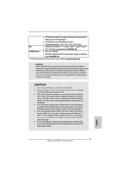
... Memory Technology, make sure to chipset limitations, overclocking is no such limitation. CAUTION! 1. Due to read the installation guide of memory modules on page 20 for proper installation. 5. This motherboard supports Dual Channel Memory Technology. For Windows® OS with IT tools, which ..., or using third-party overclocking tools. There are not responsible for system usage under Windows® 7 / VistaTM / XP. You can use ASRock XFast RAM to the components and devices of "Hyper Threading Technology", please check page 43. 3. FCC, CE, WHQL - ErP/EuP Ready (ErP...
... Memory Technology, make sure to chipset limitations, overclocking is no such limitation. CAUTION! 1. Due to read the installation guide of memory modules on page 20 for proper installation. 5. This motherboard supports Dual Channel Memory Technology. For Windows® OS with IT tools, which ..., or using third-party overclocking tools. There are not responsible for system usage under Windows® 7 / VistaTM / XP. You can use ASRock XFast RAM to the components and devices of "Hyper Threading Technology", please check page 43. 3. FCC, CE, WHQL - ErP/EuP Ready (ErP...
User Manual
Page 13
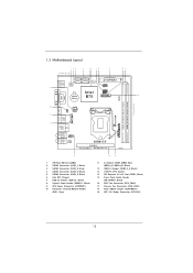
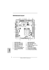
...-pin module) DDR3_B1 (64 bit, 240-pin module) 17.0cm (6.7 in) DVI1 VGA1 18 HDMI1 17 CLRCMOS1 ATX12V1 ESATA1 USB 2.0 T: USB2 B: USB3 CHA_FAN1 16 CPU_FAN1 USB 3.0 T: USB1 Top: B: USB2 RJ-45 Top: CTR BASS Center: REAR SPK Bottom: Optical SPDIF Top: LINE IN Center: FRONT Bottom: MIC IN 1 HD_AUDIO1 AUDIO CODEC B75M-ITX PCIE1...
...-pin module) DDR3_B1 (64 bit, 240-pin module) 17.0cm (6.7 in) DVI1 VGA1 18 HDMI1 17 CLRCMOS1 ATX12V1 ESATA1 USB 2.0 T: USB2 B: USB3 CHA_FAN1 16 CPU_FAN1 USB 3.0 T: USB1 Top: B: USB2 RJ-45 Top: CTR BASS Center: REAR SPK Bottom: Optical SPDIF Top: LINE IN Center: FRONT Bottom: MIC IN 1 HD_AUDIO1 AUDIO CODEC B75M-ITX PCIE1...
User Manual
Page 20
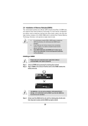
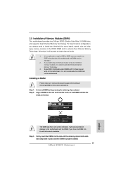
...Memory Technology. 3. Some DDR3 1GB double-sided DIMMs with 16 chips may be damaged. 2. It is unable to install a DDR or DDR2 memory module into DDR3 slot;otherwise, this motherboard and DIMM may not work on this motherboard. Installing a DIMM Please make sure to install them on the ... retaining clips at single channel mode. 1. If you always need to install two identical (the same brand, speed, size and chiptype) memory modules in place and the DIMM is not recommended to disconnect power supply before adding or removing DIMMs or the system components. It is properly seated...
...Memory Technology. 3. Some DDR3 1GB double-sided DIMMs with 16 chips may be damaged. 2. It is unable to install a DDR or DDR2 memory module into DDR3 slot;otherwise, this motherboard and DIMM may not work on this motherboard. Installing a DIMM Please make sure to install them on the ... retaining clips at single channel mode. 1. If you always need to install two identical (the same brand, speed, size and chiptype) memory modules in place and the DIMM is not recommended to disconnect power supply before adding or removing DIMMs or the system components. It is properly seated...
User Manual
Page 28
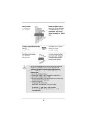
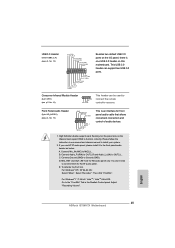
... front panel audio cable that allows convenient connection and control of audio devices. 1. Connect Audio_R (RIN) to OUT2_R and Audio_L (LIN) to MIC2_L. E. Consumer Infrared Module Header (4-pin CIR1) (see p.13, No. 15) GND PRESENCE# MIC_RET OUT_RET 1 OUT2_L J_SENSE OUT2_R MIC2_R MIC2_L This is one USB 3.0 header on the chassis must...
... front panel audio cable that allows convenient connection and control of audio devices. 1. Connect Audio_R (RIN) to OUT2_R and Audio_L (LIN) to MIC2_L. E. Consumer Infrared Module Header (4-pin CIR1) (see p.13, No. 15) GND PRESENCE# MIC_RET OUT_RET 1 OUT2_L J_SENSE OUT2_R MIC2_R MIC2_L This is one USB 3.0 header on the chassis must...
User Manual
Page 29
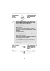
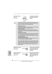
... LED): Connect to the power switch on the chassis front panel. The LED keeps blinking when the system is reading or writing data. A front panel module mainly consists of power switch, reset switch, power LED, hard drive activity LED, speaker and etc. Note the positive and negative pins before connecting the... wire to the ground pin. The LED is on when the hard drive is in S4 sleep state or powered off your chassis front panel module to turn off (S5).
... LED): Connect to the power switch on the chassis front panel. The LED keeps blinking when the system is reading or writing data. A front panel module mainly consists of power switch, reset switch, power LED, hard drive activity LED, speaker and etc. Note the positive and negative pins before connecting the... wire to the ground pin. The LED is on when the hard drive is in S4 sleep state or powered off your chassis front panel module to turn off (S5).
User Manual
Page 39
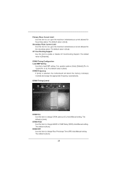
... Use this item to con gure the maximum instantaneous current allowed for the secondary plane. The default is selected, the motherboard will detect the memory module(s) inserted and assign the appropriate frequency automatically. The default value is [Auto]. The default is [Auto]. The default value is [Auto]. Primary Plane Current Limit...
... Use this item to con gure the maximum instantaneous current allowed for the secondary plane. The default is selected, the motherboard will detect the memory module(s) inserted and assign the appropriate frequency automatically. The default value is [Auto]. The default is [Auto]. The default value is [Auto]. Primary Plane Current Limit...
Quick Installation Guide
Page 2
...-pin module) DDR3_B1 (64 bit, 240-pin module) 17.0cm (6.7 in) DVI1 VGA1 18 HDMI1 17 CLRCMOS1 ATX12V1 ESATA1 USB 2.0 T: USB2 B: USB3 CHA_FAN1 16 CPU_FAN1 USB 3.0 T: USB1 Top: B: USB2 RJ-45 Top: CTR BASS Center: REAR SPK Bottom: Optical SPDIF Top: LINE IN Center: FRONT Bottom: MIC IN 1 HD_AUDIO1 AUDIO CODEC B75M-ITX PCIE1... Header (HD_AUDIO1, Black) 16 CPU Fan Connector (CPU_FAN1) 17 Chassis Fan Connector (CHA_FAN1) 18 Clear CMOS Jumper (CLRCMOS1) 19 ATX 12V Power Connector (ATX12V1) English 2 ASRock B75M-ITX Motherboard
...-pin module) DDR3_B1 (64 bit, 240-pin module) 17.0cm (6.7 in) DVI1 VGA1 18 HDMI1 17 CLRCMOS1 ATX12V1 ESATA1 USB 2.0 T: USB2 B: USB3 CHA_FAN1 16 CPU_FAN1 USB 3.0 T: USB1 Top: B: USB2 RJ-45 Top: CTR BASS Center: REAR SPK Bottom: Optical SPDIF Top: LINE IN Center: FRONT Bottom: MIC IN 1 HD_AUDIO1 AUDIO CODEC B75M-ITX PCIE1... Header (HD_AUDIO1, Black) 16 CPU Fan Connector (CPU_FAN1) 17 Chassis Fan Connector (CHA_FAN1) 18 Clear CMOS Jumper (CLRCMOS1) 19 ATX 12V Power Connector (ATX12V1) English 2 ASRock B75M-ITX Motherboard
Quick Installation Guide
Page 9
...a Sandy Bridge CPU, the PCI Express will run the PCI Express in Gen 3 speed, please install an Ivy Bridge CPU. English 9 ASRock B75M-ITX Motherboard Intel® Small Business Advantage is a certain risk involved with overclocking, including adjusting the setting in the support CD. 3. Due to... ASRock XFast RAM to chipset limitations, overclocking is no such limitation. We are applications including Software Monitor, PC Health Center, Data Backup & Restore, Energy Saver and USB Blocker. 4. About the settings of "Hyper Threading Technology", please check page 43 of memory modules ...
...a Sandy Bridge CPU, the PCI Express will run the PCI Express in Gen 3 speed, please install an Ivy Bridge CPU. English 9 ASRock B75M-ITX Motherboard Intel® Small Business Advantage is a certain risk involved with overclocking, including adjusting the setting in the support CD. 3. Due to... ASRock XFast RAM to chipset limitations, overclocking is no such limitation. We are applications including Software Monitor, PC Health Center, Data Backup & Restore, Energy Saver and USB Blocker. 4. About the settings of "Hyper Threading Technology", please check page 43 of memory modules ...
Quick Installation Guide
Page 17
... motherboard. It is not allowed to activate Dual Channel Memory Technology. It will operate at incorrect orientation. Step 3. 2.5 Installation of Memory Modules (DIMM) This motherboard provides two 240-pin DDR3 (Double Data Rate 3) DIMM slots, and supports Dual Channel Memory Technology. Unlock a DIMM... on the slot such that the notch on the DIMM matches the break on this motherboard. Otherwise, it is properly seated. 17 ASRock B75M-ITX Motherboard English Some DDR3 1GB double-sided DIMMs with 16 chips may be damaged. 2. Installing a DIMM Please make sure to activate ...
... motherboard. It is not allowed to activate Dual Channel Memory Technology. It will operate at incorrect orientation. Step 3. 2.5 Installation of Memory Modules (DIMM) This motherboard provides two 240-pin DDR3 (Double Data Rate 3) DIMM slots, and supports Dual Channel Memory Technology. Unlock a DIMM... on the slot such that the notch on the DIMM matches the break on this motherboard. Otherwise, it is properly seated. 17 ASRock B75M-ITX Motherboard English Some DDR3 1GB double-sided DIMMs with 16 chips may be damaged. 2. Installing a DIMM Please make sure to activate ...
Quick Installation Guide
Page 25
... IRRX ATX+5VSB This header can support two USB 3.0 ports. If you use AC'97 audio panel, please install it to MIC2_L. Consumer Infrared Module Header (4-pin CIR1) (see p.2, No. 15) GND PRESENCE# MIC_RET OUT_RET 1 OUT2_L J_SENSE OUT2_R MIC2_R MIC2_L This is one USB 3.0 header on... 7 64-bit / VistaTM / VistaTM 64-bit OS: Go to the "FrontMic" Tab in our manual and chassis manual to Ground (GND). English 25 ASRock B75M-ITX Motherboard To activate the front mic. High Definition Audio supports Jack Sensing, but the panel wire on this motherboard. Connect Audio_R (RIN) to...
... IRRX ATX+5VSB This header can support two USB 3.0 ports. If you use AC'97 audio panel, please install it to MIC2_L. Consumer Infrared Module Header (4-pin CIR1) (see p.2, No. 15) GND PRESENCE# MIC_RET OUT_RET 1 OUT2_L J_SENSE OUT2_R MIC2_R MIC2_L This is one USB 3.0 header on... 7 64-bit / VistaTM / VistaTM 64-bit OS: Go to the "FrontMic" Tab in our manual and chassis manual to Ground (GND). English 25 ASRock B75M-ITX Motherboard To activate the front mic. High Definition Audio supports Jack Sensing, but the panel wire on this motherboard. Connect Audio_R (RIN) to...
Quick Installation Guide
Page 26
...panel. The LED keeps blinking when the system is operating. English 26 ASRock B75M-ITX Motherboard You may differ by chassis. PLED (System Power LED): Connect to the power status indicator on the chassis front panel. A front panel module mainly consists of power switch, reset switch, power LED, hard drive ...black wire to perform a normal restart. The front panel design may configure the way to turn off your chassis front panel module to this header according to this header, make sure the wire assignments and the pin assign-ments are matched correctly. The LED is ...
...panel. The LED keeps blinking when the system is operating. English 26 ASRock B75M-ITX Motherboard You may differ by chassis. PLED (System Power LED): Connect to the power status indicator on the chassis front panel. A front panel module mainly consists of power switch, reset switch, power LED, hard drive ...black wire to perform a normal restart. The front panel design may configure the way to turn off your chassis front panel module to this header according to this header, make sure the wire assignments and the pin assign-ments are matched correctly. The LED is ...
