User Manual
Page 12
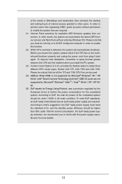
... regulated by Microsoft® Windows® VistaTM / VistaTM 64-bit / XP / XP 64bit. 25. ASRock XFast RAM is detected, the system will automatically shutdown. In order to prevent users from our servers and ...flash them without permission to modify the system time are required. 21. Intel® Smart Connect Technology and Intel® USB 3.0 ports are required. Internet Flash searches for more details. 12 EuP...power cord, then plug it back again. According to Intel's suggestion, the EuP ready power supply must be noticed that you to adopt three different CPU...
... regulated by Microsoft® Windows® VistaTM / VistaTM 64-bit / XP / XP 64bit. 25. ASRock XFast RAM is detected, the system will automatically shutdown. In order to prevent users from our servers and ...flash them without permission to modify the system time are required. 21. Intel® Smart Connect Technology and Intel® USB 3.0 ports are required. Internet Flash searches for more details. 12 EuP...power cord, then plug it back again. According to Intel's suggestion, the EuP ready power supply must be noticed that you to adopt three different CPU...
User Manual
Page 13
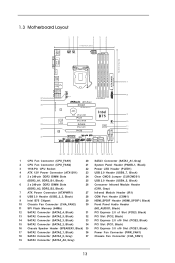
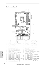
...SPK USB3_2_3 1 Top: LINE IN Center: FRONT ErP/EuP Ready PWR_FAN1 Front USB 3.0 LAN PHY Super I/O B75 Pro3 PCIE1 PCI Express 3.0 CMOS Battery XFast USB PCI1 XFast RAM PCIE2 XFast LAN Intel B75 64Mb BIOS AUDIO CODEC PCI2 HD_AUDIO1 1 PCIE3 HDMI_SPDIF1 1 COM1 IR1 1 1 1 1 CLRCMOS1 PLED1 1 RoHS1...1 CPU Fan Connector (CPU_FAN1) 20 SATA3 Connector (SATA3_A1, Gray) 2 CPU Fan Connector (CPU_FAN2) 21 System Panel Header (PANEL1, Black) 3 1155-Pin CPU Socket 22 Power LED Header (PLED1) 4 ATX 12V Power Connector (ATX12V1) 23 USB 2.0 Header (USB6_7, Black) 5 2 x 240-pin DDR3 ...
...SPK USB3_2_3 1 Top: LINE IN Center: FRONT ErP/EuP Ready PWR_FAN1 Front USB 3.0 LAN PHY Super I/O B75 Pro3 PCIE1 PCI Express 3.0 CMOS Battery XFast USB PCI1 XFast RAM PCIE2 XFast LAN Intel B75 64Mb BIOS AUDIO CODEC PCI2 HD_AUDIO1 1 PCIE3 HDMI_SPDIF1 1 COM1 IR1 1 1 1 1 CLRCMOS1 PLED1 1 RoHS1...1 CPU Fan Connector (CPU_FAN1) 20 SATA3 Connector (SATA3_A1, Gray) 2 CPU Fan Connector (CPU_FAN2) 21 System Panel Header (PANEL1, Black) 3 1155-Pin CPU Socket 22 Power LED Header (PLED1) 4 ATX 12V Power Connector (ATX12V1) 23 USB 2.0 Header (USB6_7, Black) 5 2 x 240-pin DDR3 ...

User Manual
Page 17
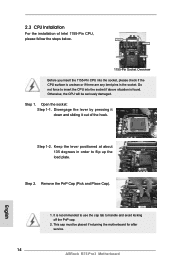
Step 1. Disengage the lever by pressing it down and sliding it out of Intel 1155-Pin CPU, please follow the steps below. 1155-Pin Socket Overview Before you insert the 1155-Pin CPU into the socket if above situation is found. Remove the PnP Cap (Pick and Place Cap). 1. It is unclean or if there are ...any bent pins in order to insert the CPU into the socket, please check if the ...
Step 1. Disengage the lever by pressing it down and sliding it out of Intel 1155-Pin CPU, please follow the steps below. 1155-Pin Socket Overview Before you insert the 1155-Pin CPU into the socket if above situation is found. Remove the PnP Cap (Pick and Place Cap). 1. It is unclean or if there are ...any bent pins in order to insert the CPU into the socket, please check if the ...
User Manual
Page 19
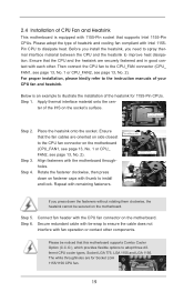
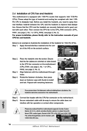
.... 2). Below is equipped with thumb to install and lock. Step 2. Please be secured on fastener caps with 1155-Pin socket that the fan cables are for 1155-Pin CPUs. Place the heatsink onto the socket. Ensure that supports Intel 1155-Pin CPUs. Step 5. 2.4 Installation of CPU Fan and Heatsink This motherboard is an example to illustrate...
.... 2). Below is equipped with thumb to install and lock. Step 2. Please be secured on fastener caps with 1155-Pin socket that the fan cables are for 1155-Pin CPUs. Place the heatsink onto the socket. Ensure that supports Intel 1155-Pin CPUs. Step 5. 2.4 Installation of CPU Fan and Heatsink This motherboard is an example to illustrate...
Quick Installation Guide
Page 2
... IN Center: FRONT ErP/EuP Ready PWR_FAN1 Front USB 3.0 LAN PHY Super I/O B75 Pro3 PCIE1 PCI Express 3.0 CMOS Battery XFast USB PCI1 XFast RAM PCIE2 XFast LAN Intel B75 64Mb BIOS AUDIO CODEC PCI2 HD_AUDIO1 1 PCIE3 HDMI_SPDIF1 1 COM1 IR1 1 1 ...) 20 SATA3 Connector (SATA3_A1, Gray) 2 CPU Fan Connector (CPU_FAN2) 21 System Panel Header (PANEL1, Black) 3 1155-Pin CPU Socket 22 Power LED Header (PLED1) 4 ATX 12V Power Connector (ATX12V1) 23 USB 2.0 Header (USB6_7, Black) 5 ... Fan Connector (CHA_FAN1) 19 SATA3 Connector (SATA3_A0, Gray) 2 ASRock B75 Pro3 Motherboard English
... IN Center: FRONT ErP/EuP Ready PWR_FAN1 Front USB 3.0 LAN PHY Super I/O B75 Pro3 PCIE1 PCI Express 3.0 CMOS Battery XFast USB PCI1 XFast RAM PCIE2 XFast LAN Intel B75 64Mb BIOS AUDIO CODEC PCI2 HD_AUDIO1 1 PCIE3 HDMI_SPDIF1 1 COM1 IR1 1 1 ...) 20 SATA3 Connector (SATA3_A1, Gray) 2 CPU Fan Connector (CPU_FAN2) 21 System Panel Header (PANEL1, Black) 3 1155-Pin CPU Socket 22 Power LED Header (PLED1) 4 ATX 12V Power Connector (ATX12V1) 23 USB 2.0 Header (USB6_7, Black) 5 ... Fan Connector (CHA_FAN1) 19 SATA3 Connector (SATA3_A0, Gray) 2 ASRock B75 Pro3 Motherboard English
Quick Installation Guide
Page 12
...our servers. To improve heat dissipation, remember to enable this function. 22. Intel® Smart Connect Technology and Intel® USB 3.0 ports are required. Please note that not all the 775...regulated by the European Union to check with the power supply manufacturer for more details. 12 ASRock B75 Pro3 Motherboard English For EuP ready power supply selection, we recommend you resume the system, please check...and ending hours of internet access granted to adopt three different CPU cooler types, Socket LGA 775, LGA 1155 and LGA 1156. To meet the standard of 5v, and the standby power ...
...our servers. To improve heat dissipation, remember to enable this function. 22. Intel® Smart Connect Technology and Intel® USB 3.0 ports are required. Please note that not all the 775...regulated by the European Union to check with the power supply manufacturer for more details. 12 ASRock B75 Pro3 Motherboard English For EuP ready power supply selection, we recommend you resume the system, please check...and ending hours of internet access granted to adopt three different CPU cooler types, Socket LGA 775, LGA 1155 and LGA 1156. To meet the standard of 5v, and the standby power ...
Quick Installation Guide
Page 14
... 1-1. Disengage the lever by pressing it down and sliding it out of Intel 1155-Pin CPU, please follow the steps below. 1155-Pin Socket Overview Before you insert the 1155-Pin CPU into the socket, please check if the CPU surface is unclean or if there are any bent pins in order to ... damaged. 2.3 CPU Installation For the installation of the hook. Otherwise, the CPU will be placed if returning the motherboard for after service. 14 ASRock B75 Pro3 Motherboard English Step 1. Do not force to flip up the load plate. Step 2. Keep the lever positioned at about 135 degrees in the...
... 1-1. Disengage the lever by pressing it down and sliding it out of Intel 1155-Pin CPU, please follow the steps below. 1155-Pin Socket Overview Before you insert the 1155-Pin CPU into the socket, please check if the CPU surface is unclean or if there are any bent pins in order to ... damaged. 2.3 CPU Installation For the installation of the hook. Otherwise, the CPU will be placed if returning the motherboard for after service. 14 ASRock B75 Pro3 Motherboard English Step 1. Do not force to flip up the load plate. Step 2. Keep the lever positioned at about 135 degrees in the...
Quick Installation Guide
Page 16
...is an example to illustrate the installation of the heatsink for Socket LGA 1155/1156 CPU fan. 16 ASRock B75 Pro3 Motherboard English Step 1. Step 3. Step 4. Connect fan header with the CPU fan connector on fastener caps with Intel 1155Pin CPU to dissipate heat. Secure redundant cable with tie...with each other components. Before you install the heatsink, you press down on the motherboard. Ensure that supports Intel 1155-Pin CPUs. Below is equipped with 1155-Pin socket that the CPU and the heatsink are securely fastened and in good contact with remaining fasteners.
...is an example to illustrate the installation of the heatsink for Socket LGA 1155/1156 CPU fan. 16 ASRock B75 Pro3 Motherboard English Step 1. Step 3. Step 4. Connect fan header with the CPU fan connector on fastener caps with Intel 1155Pin CPU to dissipate heat. Secure redundant cable with tie...with each other components. Before you install the heatsink, you press down on the motherboard. Ensure that supports Intel 1155-Pin CPUs. Below is equipped with 1155-Pin socket that the CPU and the heatsink are securely fastened and in good contact with remaining fasteners.


