User Manual
Page 2
...the following two conditions: (1) this device may not cause harmful interference, and (2) this documentation may or may appear in this motherboard contains Perchlorate, a toxic substance controlled in the documentation or product. When you discard the Lithium battery in California, USA, please...documentation may apply, see www.dtsc.ca.gov/hazardouswaste/ perchlorate" ASRock Website: http://www.asrock.com Version 1.0 Published May 2020 Copyright©2020 ASRock INC. Copyright Notice: No part of this documentation, ASRock does not provide warranty of any means, except duplication of ...
...the following two conditions: (1) this device may not cause harmful interference, and (2) this documentation may or may appear in this motherboard contains Perchlorate, a toxic substance controlled in the documentation or product. When you discard the Lithium battery in California, USA, please...documentation may apply, see www.dtsc.ca.gov/hazardouswaste/ perchlorate" ASRock Website: http://www.asrock.com Version 1.0 Published May 2020 Copyright©2020 ASRock INC. Copyright Notice: No part of this documentation, ASRock does not provide warranty of any means, except duplication of ...
User Manual
Page 4
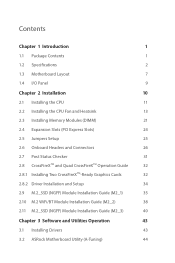
Contents Chapter 1 Introduction 1 1.1 Package Contents 1 1.2 Specifications 2 1.3 Motherboard Layout 7 1.4 I/O Panel 9 Chapter 2 Installation 10 2.1 Installing the CPU 11 2.2 Installing the CPU Fan and Heatsink 13 2.3 Installing Memory Modules (DIMM) 21 2.4 Expansion Slots (PCI Express ... 2.10 M.2 WiFi/BT Module Installation Guide (M2_2) 38 2.11 M.2_SSD (NGFF) Module Installation Guide (M2_3) 40 Chapter 3 Software and Utilities Operation 43 3.1 Installing Drivers 43 3.2 ASRock Motherboard Utility (A-Tuning) 44
Contents Chapter 1 Introduction 1 1.1 Package Contents 1 1.2 Specifications 2 1.3 Motherboard Layout 7 1.4 I/O Panel 9 Chapter 2 Installation 10 2.1 Installing the CPU 11 2.2 Installing the CPU Fan and Heatsink 13 2.3 Installing Memory Modules (DIMM) 21 2.4 Expansion Slots (PCI Express ... 2.10 M.2 WiFi/BT Module Installation Guide (M2_2) 38 2.11 M.2_SSD (NGFF) Module Installation Guide (M2_3) 40 Chapter 3 Software and Utilities Operation 43 3.1 Installing Drivers 43 3.2 ASRock Motherboard Utility (A-Tuning) 44
User Manual
Page 7
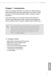
... the operation guide of the BIOS setup. ASRock website http://www.asrock.com. 1.1 Package Contents • ASRock B550 Pro4 Motherboard (ATX Form Factor) • ASRock B550 Pro4 Quick Installation Guide • ASRock B550 Pro4 Support CD • 2 x Serial ATA (SATA) Data Cables (Optional) • 3 x Screws for M.2 Sockets (Optional) • 1 x Standoff for purchasing ASRock B550 Pro4 motherboard, a reliable motherboard produced under ASRock's consistently stringent quality control. It delivers excellent...
... the operation guide of the BIOS setup. ASRock website http://www.asrock.com. 1.1 Package Contents • ASRock B550 Pro4 Motherboard (ATX Form Factor) • ASRock B550 Pro4 Quick Installation Guide • ASRock B550 Pro4 Support CD • 2 x Serial ATA (SATA) Data Cables (Optional) • 3 x Screws for M.2 Sockets (Optional) • 1 x Standoff for purchasing ASRock B550 Pro4 motherboard, a reliable motherboard produced under ASRock's consistently stringent quality control. It delivers excellent...
User Manual
Page 13
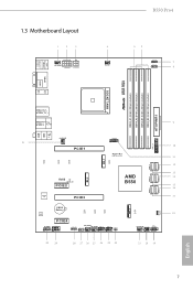
1.3 Motherboard Layout 1 2 3 CPU_FAN2/WP ATX12V1 ATX12V2 B550 Pro4 4 CPU_FAN1 56 RGB_LED2 1 7 ADDR_LED2 1 8 PS2 Keyboard /Mouse USB 3.2 Gen1 T: USB3_1 B: USB3_2 VGA1 HDMI1 DDR4_A1 (64 bit, 288-pin module) DDR4_A2 (64 bit, ... IN USB3_7_8 31 CHA_FAN3/WP PCIE1 CT1 CT2 CT3 SPI_TPM_J1 1 Hyper M.2 PCIe Gen4 x4 CT8 SATA3_5 SATA3_6 M2_2 M2_1 SATA3_3 SATA3_4 RoHS M2_WIFI_CT1 PCIE2 AMD B550 SATA3_1 SATA3_2 SUPER I/O PCIE3 CMOS Battery AUDIO CODEC CT5 CT6 CT7 PCIE4 HD_AUDIO1 1 1 COM1 CHA_FAN4/WP RGB_LED1 CHA_FAN2/WP ADDR_LED1 1 1 1 USB_1_2 1 USB_3_4 ...
1.3 Motherboard Layout 1 2 3 CPU_FAN2/WP ATX12V1 ATX12V2 B550 Pro4 4 CPU_FAN1 56 RGB_LED2 1 7 ADDR_LED2 1 8 PS2 Keyboard /Mouse USB 3.2 Gen1 T: USB3_1 B: USB3_2 VGA1 HDMI1 DDR4_A1 (64 bit, 288-pin module) DDR4_A2 (64 bit, ... IN USB3_7_8 31 CHA_FAN3/WP PCIE1 CT1 CT2 CT3 SPI_TPM_J1 1 Hyper M.2 PCIe Gen4 x4 CT8 SATA3_5 SATA3_6 M2_2 M2_1 SATA3_3 SATA3_4 RoHS M2_WIFI_CT1 PCIE2 AMD B550 SATA3_1 SATA3_2 SUPER I/O PCIE3 CMOS Battery AUDIO CODEC CT5 CT6 CT7 PCIE4 HD_AUDIO1 1 1 COM1 CHA_FAN4/WP RGB_LED1 CHA_FAN2/WP ADDR_LED1 1 1 1 USB_1_2 1 USB_3_4 ...
User Manual
Page 16
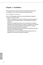
... In order to avoid damage from static electricity to the chassis, please do not touch the ICs. • Whenever you install the motherboard, study the configuration of the following precautions before you handle the components. • Hold components by the edges and do not overtighten ..., place them on a carpet. Chapter 2 Installation This is an ATX form factor motherboard. Pre-installation Precautions Take note of your motherboard directly on a grounded anti-static pad or in the bag that the motherboard fits into it. Also remember to use a grounded wrist strap or touch a safety...
... In order to avoid damage from static electricity to the chassis, please do not touch the ICs. • Whenever you install the motherboard, study the configuration of the following precautions before you handle the components. • Hold components by the edges and do not overtighten ..., place them on a carpet. Chapter 2 Installation This is an ATX form factor motherboard. Pre-installation Precautions Take note of your motherboard directly on a grounded anti-static pad or in the bag that the motherboard fits into it. Also remember to use a grounded wrist strap or touch a safety...

User Manual
Page 19
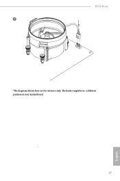
Make sure that the CPU and the heatsink are securely fastened and in good contact with each other. Installing the CPU Box Cooler SR1 1 2 13 English Please turn off the power or remove the power cord before changing a CPU or heatsink. You also need to spray thermal grease between the CPU and the heatsink to dissipate heat. B550 Pro4 2.2 Installing the CPU Fan and Heatsink After you install the CPU into this motherboard, it is necessary to install a larger heatsink and cooling fan to improve heat dissipation.
Make sure that the CPU and the heatsink are securely fastened and in good contact with each other. Installing the CPU Box Cooler SR1 1 2 13 English Please turn off the power or remove the power cord before changing a CPU or heatsink. You also need to spray thermal grease between the CPU and the heatsink to dissipate heat. B550 Pro4 2.2 Installing the CPU Fan and Heatsink After you install the CPU into this motherboard, it is necessary to install a larger heatsink and cooling fan to improve heat dissipation.
User Manual
Page 23
B550 Pro4 4 CPU_FAN1 *The diagrams shown here are for reference only. The header might be in a different position on your motherboard. 17 English
B550 Pro4 4 CPU_FAN1 *The diagrams shown here are for reference only. The header might be in a different position on your motherboard. 17 English
User Manual
Page 26
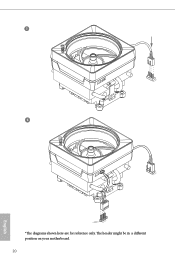
The header might be in a different position on your motherboard. 20 English 5 CPU_FAN1 6 CPU_FAN1 +12V RGB_LED2 *The diagrams shown here are for reference only.
The header might be in a different position on your motherboard. 20 English 5 CPU_FAN1 6 CPU_FAN1 +12V RGB_LED2 *The diagrams shown here are for reference only.
User Manual
Page 27
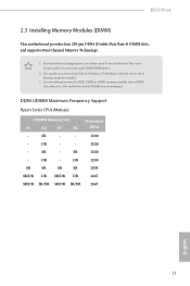
B550 Pro4 2.3 Installing Memory Modules (DIMM) This motherboard provides four 288-pin DDR4 (Double Data Rate 4) DIMM slots, and supports Dual Channel Memory Technology. 1. SR - - 3200 - DR - SR 3200 - It is not allowed .../DR SR/DR 2667 English 21 It is unable to install identical (the same brand, speed, size and chip-type) DDR4 DIMM pairs. 2. otherwise, this motherboard and DIMM may be damaged. DDR4 UDIMM Maximum Frequency Support Ryzen Series CPUs (Matisse): UDIMM Memory Slot A1 A2 B1 B2 Frequency (Mhz) - DR - - 3200...
B550 Pro4 2.3 Installing Memory Modules (DIMM) This motherboard provides four 288-pin DDR4 (Double Data Rate 4) DIMM slots, and supports Dual Channel Memory Technology. 1. SR - - 3200 - DR - SR 3200 - It is not allowed .../DR SR/DR 2667 English 21 It is unable to install identical (the same brand, speed, size and chip-type) DDR4 DIMM pairs. 2. otherwise, this motherboard and DIMM may be damaged. DDR4 UDIMM Maximum Frequency Support Ryzen Series CPUs (Matisse): UDIMM Memory Slot A1 A2 B1 B2 Frequency (Mhz) - DR - - 3200...
User Manual
Page 29
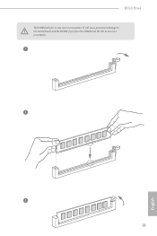
It will cause permanent damage to the motherboard and the DIMM if you force the DIMM into the slot at incorrect orientation. 1 2 3 23 English B550 Pro4 The DIMM only fits in one correct orientation.
It will cause permanent damage to the motherboard and the DIMM if you force the DIMM into the slot at incorrect orientation. 1 2 3 23 English B550 Pro4 The DIMM only fits in one correct orientation.
User Manual
Page 30
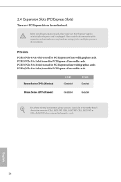
... cards. Ryzen Series CPUs (Matisse) PCIE1 Gen4x16 PCIE3 Gen3x4 Ryzen Series APUs (Renoir) Gen3x16 Gen3x4 For a better thermal environment, please connect a chassis fan to the motherboard's chassis fan connector (CHA_FAN1/WP, CHA_FAN2/WP, CHA_FAN3/WP or CHA_FAN4/WP) when using multiple graphics cards. Please read the documentation of the expansion card..., please make necessary hardware settings for PCI Express x4 lane width graphics cards. 2.4 Expansion Slots (PCI Express Slots) There are 4 PCI Express slots on the motherboard. English 24
... cards. Ryzen Series CPUs (Matisse) PCIE1 Gen4x16 PCIE3 Gen3x4 Ryzen Series APUs (Renoir) Gen3x16 Gen3x4 For a better thermal environment, please connect a chassis fan to the motherboard's chassis fan connector (CHA_FAN1/WP, CHA_FAN2/WP, CHA_FAN3/WP or CHA_FAN4/WP) when using multiple graphics cards. Please read the documentation of the expansion card..., please make necessary hardware settings for PCI Express x4 lane width graphics cards. 2.4 Expansion Slots (PCI Express Slots) There are 4 PCI Express slots on the motherboard. English 24
User Manual
Page 32
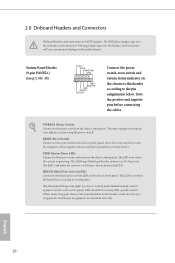
... caps over the headers and connectors will cause permanent damage to the power switch on the chassis front panel. PWRBTN (Power Switch): Connect to the motherboard. PLED (System Power LED): Connect to the hard drive activity LED on the chassis front panel. The LED is off your chassis front panel module...
... caps over the headers and connectors will cause permanent damage to the power switch on the chassis front panel. PWRBTN (Power Switch): Connect to the motherboard. PLED (System Power LED): Connect to the hard drive activity LED on the chassis front panel. The LED is off your chassis front panel module...
User Manual
Page 33
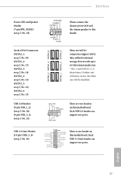
... USB3_7_8) (see p.7, No. 23) SATA3_2 SATA3_4 SATA3_6 SATA3_1 SATA3_3 SATA3_5 SPEAKER DUMMY DUMMY +5V 1 PLED+ PLED+ PLED- Each USB 3.2 Gen1 header can support two ports. B550 Pro4 Power LED and Speaker Header (7-pin SPK_PLED1) (see p.7, No. 20) Serial ATA3 Connectors (SATA3_1: see p.7, No. 16) (SATA3_2: see p.7, No. 17) (SATA3_3: see p.7, No.... USB 2.0 header can support two ports. English 27 These six SATA3 connectors support SATA data cables for internal storage devices with up to this motherboard. USB_PWR PP+ GND DUMMY 1 GND P+ PUSB_PWR There are two headers on this...
... USB3_7_8) (see p.7, No. 23) SATA3_2 SATA3_4 SATA3_6 SATA3_1 SATA3_3 SATA3_5 SPEAKER DUMMY DUMMY +5V 1 PLED+ PLED+ PLED- Each USB 3.2 Gen1 header can support two ports. B550 Pro4 Power LED and Speaker Header (7-pin SPK_PLED1) (see p.7, No. 20) Serial ATA3 Connectors (SATA3_1: see p.7, No. 16) (SATA3_2: see p.7, No. 17) (SATA3_3: see p.7, No.... USB 2.0 header can support two ports. English 27 These six SATA3 connectors support SATA data cables for internal storage devices with up to this motherboard. USB_PWR PP+ GND DUMMY 1 GND P+ PUSB_PWR There are two headers on this...
User Manual
Page 34
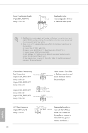
... system. 2. B. MIC_RET and OUT_RET are for the AC'97 audio panel. E. Front Panel Audio Header (9-pin HD_AUDIO1) (see p.7, No. 4) 28 FAN_VOLTAGE CPU_FAN_SPEED GND FAN_SPEED_CONTROL 1 2 3 4 This motherboard provides a 4-Pin CPU fan (Quiet Fan) connector. Please follow the instructions in the Realtek Control panel and adjust "Recording Volume". Chassis Fan / Waterpump Please connect...
... system. 2. B. MIC_RET and OUT_RET are for the AC'97 audio panel. E. Front Panel Audio Header (9-pin HD_AUDIO1) (see p.7, No. 4) 28 FAN_VOLTAGE CPU_FAN_SPEED GND FAN_SPEED_CONTROL 1 2 3 4 This motherboard provides a 4-Pin CPU fan (Quiet Fan) connector. Please follow the instructions in the Realtek Control panel and adjust "Recording Volume". Chassis Fan / Waterpump Please connect...
User Manual
Page 35
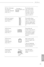
... power connector. ATX 12V Power Connector (8-pin ATX12V1) (see p.7, No. 1) FAN_VOLTAGE This motherboard pro- To use a 20-pin ATX power supply, please plug it along Pin 1 and Pin 5. B550 Pro4 CPU Fan / Waterpump Fan Connector (4-pin CPU_FAN2/WP) (see p.7, No. 2) This motherboard 8 5 provides a 8-pin ATX 12V power connector. To use a 4 1 4-pin ATX power supply...
... power connector. ATX 12V Power Connector (8-pin ATX12V1) (see p.7, No. 1) FAN_VOLTAGE This motherboard pro- To use a 20-pin ATX power supply, please plug it along Pin 1 and Pin 5. B550 Pro4 CPU Fan / Waterpump Fan Connector (4-pin CPU_FAN2/WP) (see p.7, No. 2) This motherboard 8 5 provides a 8-pin ATX 12V power connector. To use a 4 1 4-pin ATX power supply...
User Manual
Page 38
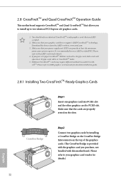
... top of the graphics cards. (The CrossFire Bridge is recommended to two identical PCI Express x16 graphics cards. 1. 2.8 CrossFireXTM and Quad CrossFireXTM Operation Guide This motherboard supports CrossFireXTM and Quad CrossFireXTM that your graphics card driver supports AMD CrossFireXTM technology. Make sure that allows you pair a 12-pipe CrossFireXTM Edition card...
... top of the graphics cards. (The CrossFire Bridge is recommended to two identical PCI Express x16 graphics cards. 1. 2.8 CrossFireXTM and Quad CrossFireXTM Operation Guide This motherboard supports CrossFireXTM and Quad CrossFireXTM that your graphics card driver supports AMD CrossFireXTM technology. Make sure that allows you pair a 12-pipe CrossFireXTM Edition card...
User Manual
Page 42
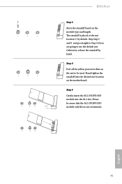
... screw as this might damage the module. Please be aware that comes with a screwdriver to remove the M.2 heatsink. *Please remove the protective films on the motherboard. English 36 Align and gently insert the M.2 (NGFF) SSD module into the desired nut location on the bottom side of the M.2 heatsink before you install...
... screw as this might damage the module. Please be aware that comes with a screwdriver to remove the M.2 heatsink. *Please remove the protective films on the motherboard. English 36 Align and gently insert the M.2 (NGFF) SSD module into the desired nut location on the bottom side of the M.2 heatsink before you install...
User Manual
Page 47
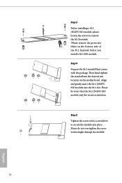
... straight to Step 5 if you are going to be aware that the M.2 (NGFF) SSD module only fits in one orientation. C B A C B A C B A 20o B550 Pro4 Step 3 Move the standoff based on the motherboard. Otherwise, release the standoff by default. The standoff is placed at the nut location C by hand. Hand tighten the standoff into the...
... straight to Step 5 if you are going to be aware that the M.2 (NGFF) SSD module only fits in one orientation. C B A C B A C B A 20o B550 Pro4 Step 3 Move the standoff based on the motherboard. Otherwise, release the standoff by default. The standoff is placed at the nut location C by hand. Hand tighten the standoff into the...
User Manual
Page 49
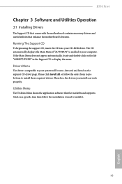
B550 Pro4 Chapter 3 Software and Utilities Operation 3.1 Installing Drivers The Support CD that comes with the motherboard contains necessary drivers and useful utilities that the motherboard supports. Please click Install All or follow the installation wizard to install those required drivers. If the Main Menu... order from top to bottom to install it. 43 English Utilities Menu The Utilities Menu shows the application software that enhance the motherboard's features. The CD automatically displays the Main Menu if "AUTORUN" is enabled in the Support CD to your computer. Click on...
B550 Pro4 Chapter 3 Software and Utilities Operation 3.1 Installing Drivers The Support CD that comes with the motherboard contains necessary drivers and useful utilities that the motherboard supports. Please click Install All or follow the installation wizard to install those required drivers. If the Main Menu... order from top to bottom to install it. 43 English Utilities Menu The Utilities Menu shows the application software that enhance the motherboard's features. The CD automatically displays the Main Menu if "AUTORUN" is enabled in the Support CD to your computer. Click on...
User Manual
Page 50
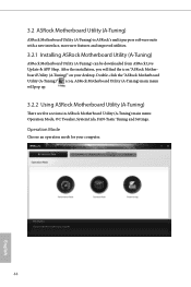
... for your desktop. Double-click the "ASRock Motherboard Utility (A-Tuning)" icon, ASRock Motherboard Utility (A-Tuning) main menu will find the icon "ASRock Motherboard Utility (A-Tuning)" on your computer. 44 English 3.2 ASRock Motherboard Utility (A-Tuning) ASRock Motherboard Utility (A-Tuning) is ASRock's multi purpose software suite with a new interface, more new features and improved utilities. 3.2.1 Installing ASRock Motherboard Utility (A-Tuning) ASRock Motherboard Utility (A-Tuning) can be downloaded...
... for your desktop. Double-click the "ASRock Motherboard Utility (A-Tuning)" icon, ASRock Motherboard Utility (A-Tuning) main menu will find the icon "ASRock Motherboard Utility (A-Tuning)" on your computer. 44 English 3.2 ASRock Motherboard Utility (A-Tuning) ASRock Motherboard Utility (A-Tuning) is ASRock's multi purpose software suite with a new interface, more new features and improved utilities. 3.2.1 Installing ASRock Motherboard Utility (A-Tuning) ASRock Motherboard Utility (A-Tuning) can be downloaded...


