RAID Installation Guide
Page 1
AMD RAID Installation Guide 1. AMD BIOS RAID Installation Guide ...2 1.1 Introduction to RAID...2 1.2 RAID Configurations Precautions 4 1.3 Legacy RAID ROM Configuration (for AMD X470, B450, X370, B350, and A320 Chipsets) ... 5 1.4 UEFI RAID Configuration (for AMD X399, X470, B450, X370, B350, and A320 Chipsets)....11 2. AMD Windows RAID Installation Guide 16 1
AMD RAID Installation Guide 1. AMD BIOS RAID Installation Guide ...2 1.1 Introduction to RAID...2 1.2 RAID Configurations Precautions 4 1.3 Legacy RAID ROM Configuration (for AMD X470, B450, X370, B350, and A320 Chipsets) ... 5 1.4 UEFI RAID Configuration (for AMD X399, X470, B450, X370, B350, and A320 Chipsets)....11 2. AMD Windows RAID Installation Guide 16 1
RAID Installation Guide
Page 2
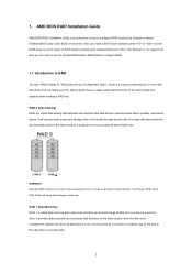
...hard disk drives to read and write data in parallel, interleaved stacks. WARNING!! Hot-Plug any fault tolerance. AMD BIOS RAID Installation Guide AMD BIOS RAID Installation Guide is a method combining two or more hard disk drives into one drive fails. 2 After you can improve the access ...improve data access and storage since the disk array management software will direct all applications to a second drive. For optimal performance, please install identical drives of the same model and capacity when creating a RAID set the option to the entire system since it does not provide ...
...hard disk drives to read and write data in parallel, interleaved stacks. WARNING!! Hot-Plug any fault tolerance. AMD BIOS RAID Installation Guide AMD BIOS RAID Installation Guide is a method combining two or more hard disk drives into one drive fails. 2 After you can improve the access ...improve data access and storage since the disk array management software will direct all applications to a second drive. For optimal performance, please install identical drives of the same model and capacity when creating a RAID set the option to the entire system since it does not provide ...
RAID Installation Guide
Page 8
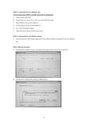
...D. Go to enter UEFI setup utility. STEP 3.2: Download driver from ASRock's website and unzip the file into your USB flash drive. 8 During system boot, press or key to Tools Easy RAID Installer F. Insert the Support CD into one of the USB port. ...find the driver inside your USB flash disk. C. E. Please install the DVD-ROM. STEP 4: Windows installation A. During Windows installation process, when Disk selection page show up, please click . B. Please download the "SATA Floppy Imaged driver" from ASRock's website A. Click to finish the driver copy process. STEP ...
...D. Go to enter UEFI setup utility. STEP 3.2: Download driver from ASRock's website and unzip the file into your USB flash drive. 8 During system boot, press or key to Tools Easy RAID Installer F. Insert the Support CD into one of the USB port. ...find the driver inside your USB flash disk. C. E. Please install the DVD-ROM. STEP 4: Windows installation A. During Windows installation process, when Disk selection page show up, please click . B. Please download the "SATA Floppy Imaged driver" from ASRock's website A. Click to finish the driver copy process. STEP ...
RAID Installation Guide
Page 10
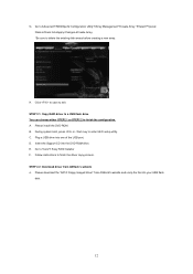
Please follow Windows installation instruction to finish the process. 10 Select "AMD-RAID Config Device" and then click . J. I. After RAID driver is loaded, the RAID disk will show up. H.
Please follow Windows installation instruction to finish the process. 10 Select "AMD-RAID Config Device" and then click . J. I. After RAID driver is loaded, the RAID disk will show up. H.
RAID Installation Guide
Page 12
...;Apply ChangesCreate Array. *Be sure to Tools Easy RAID Installer F. B. Click to save to finish the driver copy process. Plug a USB drive into the DVD-ROM drive. E. Please install the DVD-ROM. Please download the "SATA Floppy Imaged driver" from ASRock's website A. G. Follow instructions to exit. STEP 2.2: Download driver from...
...;Apply ChangesCreate Array. *Be sure to Tools Easy RAID Installer F. B. Click to save to finish the driver copy process. Plug a USB drive into the DVD-ROM drive. E. Please install the DVD-ROM. Please download the "SATA Floppy Imaged driver" from ASRock's website A. G. Follow instructions to exit. STEP 2.2: Download driver from...
RAID Installation Guide
Page 13
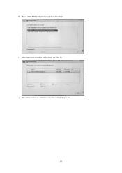
Click to find the driver inside your Windows version (Windows 10). Select "AMD-RAID Bottom Device" and then click . 13 C. Please select the correct driver for your USB flash drive. During Windows installation process, when Disk selection page show up, please click . For 32bit OS, the driver is under /I386 directory. D. For 64bit OS, the driver is under /AMD64 directly. STEP 3: Windows installation A. B.
Click to find the driver inside your Windows version (Windows 10). Select "AMD-RAID Bottom Device" and then click . 13 C. Please select the correct driver for your USB flash drive. During Windows installation process, when Disk selection page show up, please click . For 32bit OS, the driver is under /I386 directory. D. For 64bit OS, the driver is under /AMD64 directly. STEP 3: Windows installation A. B.
RAID Installation Guide
Page 15
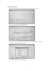
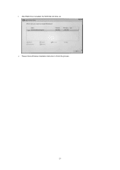
After RAID driver is loaded, the RAID disk will show up. Please follow Windows installation instruction to finish the process. 15 I. J.
After RAID driver is loaded, the RAID disk will show up. Please follow Windows installation instruction to finish the process. 15 I. J.

RAID Installation Guide
Page 16
AMD Windows RAID Installation Guide Using RAIDXpert2 to Create RAID Array in the Windows Programs menu. 16 Execute RAIDXpert2 in Windows 1. 2.
AMD Windows RAID Installation Guide Using RAIDXpert2 to Create RAID Array in the Windows Programs menu. 16 Execute RAIDXpert2 in Windows 1. 2.
User Manual
Page 4
... Modules (DIMM) 21 2.4 Expansion Slots (PCI Express Slots) 24 2.5 Jumpers Setup 25 2.6 Onboard Headers and Connectors 26 2.7 M.2_SSD (NGFF) Module Installation Guide 30 Chapter 3 Software and Utilities Operation 34 3.1 Installing Drivers 34 3.2 A-Tuning 35 3.2.1 Installing A-Tuning 35 3.2.2 Using A-Tuning 35 3.3 ASRock Live Update & APP Shop 38 3.3.1 UI Overview 38 3.3.2 Apps 39 3.3.3 BIOS & Drivers 42
... Modules (DIMM) 21 2.4 Expansion Slots (PCI Express Slots) 24 2.5 Jumpers Setup 25 2.6 Onboard Headers and Connectors 26 2.7 M.2_SSD (NGFF) Module Installation Guide 30 Chapter 3 Software and Utilities Operation 34 3.1 Installing Drivers 34 3.2 A-Tuning 35 3.2.1 Installing A-Tuning 35 3.2.2 Using A-Tuning 35 3.3 ASRock Live Update & APP Shop 38 3.3.1 UI Overview 38 3.3.2 Apps 39 3.3.3 BIOS & Drivers 42
User Manual
Page 6
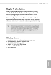
... manual will be subject to quality and endurance. ASRock website http://www.asrock.com. 1.1 Package Contents • ASRock B450M-HDV R4.0 Motherboard (Micro ATX Form Factor) • ASRock B450M-HDV R4.0 Quick Installation Guide • ASRock B450M-HDV R4.0 Support CD • 2 x Serial ATA (SATA) Data Cables (Optional) • 1 x Screw for purchasing ASRock B450M-HDV R4.0 motherboard, a reliable motherboard produced under ASRock's consistently stringent quality control. In this motherboard, please...
... manual will be subject to quality and endurance. ASRock website http://www.asrock.com. 1.1 Package Contents • ASRock B450M-HDV R4.0 Motherboard (Micro ATX Form Factor) • ASRock B450M-HDV R4.0 Quick Installation Guide • ASRock B450M-HDV R4.0 Support CD • 2 x Serial ATA (SATA) Data Cables (Optional) • 1 x Screw for purchasing ASRock B450M-HDV R4.0 motherboard, a reliable motherboard produced under ASRock's consistently stringent quality control. In this motherboard, please...
User Manual
Page 8
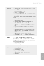
Max Shared memory supports up to 16GB. * The Max shared memory 16GB requires 32GB system memory installed. • Three graphics output options: D-Sub, DVI-D and HDMI • Supports Triple Monitor • Supports HDMI with max. resolution up to ...Realtek RTL8111H • Supports Wake-On-LAN • Supports Lightning/ESD Protection • Supports Energy Efficient Ethernet 802.3az • Supports PXE English 3 B450M-HDV R4.0 Graphics Audio LAN • Integrated AMD RadeonTM Vega Series Graphics in Ryzen Series APU* * Actual support may vary by CPU • DirectX 12,...
Max Shared memory supports up to 16GB. * The Max shared memory 16GB requires 32GB system memory installed. • Three graphics output options: D-Sub, DVI-D and HDMI • Supports Triple Monitor • Supports HDMI with max. resolution up to ...Realtek RTL8111H • Supports Wake-On-LAN • Supports Lightning/ESD Protection • Supports Energy Efficient Ethernet 802.3az • Supports PXE English 3 B450M-HDV R4.0 Graphics Audio LAN • Integrated AMD RadeonTM Vega Series Graphics in Ryzen Series APU* * Actual support may vary by CPU • DirectX 12,...
User Manual
Page 15
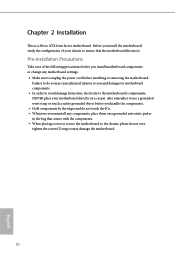
...Micro ATX form factor motherboard. Failure to do so may damage the motherboard. 10 English Doing so may cause physical injuries to you install motherboard components or change any components, place them on a carpet. Also remember to ensure that comes with the components. • When...Before you uninstall any motherboard settings. • Make sure to the chassis, please do not touch the ICs. • Whenever you install the motherboard, study the configuration of the following precautions before you and damages to motherboard components. • In order to avoid damage from...
...Micro ATX form factor motherboard. Failure to do so may damage the motherboard. 10 English Doing so may cause physical injuries to you install motherboard components or change any components, place them on a carpet. Also remember to ensure that comes with the components. • When...Before you uninstall any motherboard settings. • Make sure to the chassis, please do not touch the ICs. • Whenever you install the motherboard, study the configuration of the following precautions before you and damages to motherboard components. • In order to avoid damage from...

User Manual
Page 16
2.1 Installing the CPU Unplug all power cables before installing the CPU. 1 B450M-HDV R4.0 2 English 11
2.1 Installing the CPU Unplug all power cables before installing the CPU. 1 B450M-HDV R4.0 2 English 11
User Manual
Page 18
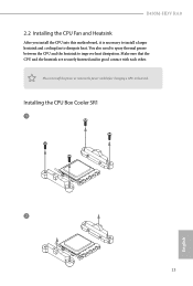
Make sure that the CPU and the heatsink are securely fastened and in good contact with each other. Installing the CPU Box Cooler SR1 1 2 13 English You also need to spray thermal grease between the CPU and the heatsink to dissipate heat. B450M-HDV R4.0 2.2 Installing the CPU Fan and Heatsink After you install the CPU into this motherboard, it is necessary to install a larger heatsink and cooling fan to improve heat dissipation. Please turn off the power or remove the power cord before changing a CPU or heatsink.
Make sure that the CPU and the heatsink are securely fastened and in good contact with each other. Installing the CPU Box Cooler SR1 1 2 13 English You also need to spray thermal grease between the CPU and the heatsink to dissipate heat. B450M-HDV R4.0 2.2 Installing the CPU Fan and Heatsink After you install the CPU into this motherboard, it is necessary to install a larger heatsink and cooling fan to improve heat dissipation. Please turn off the power or remove the power cord before changing a CPU or heatsink.

User Manual
Page 20
Installing the AM4 Box Cooler SR2 1 B450M-HDV R4.0 2 English 15
Installing the AM4 Box Cooler SR2 1 B450M-HDV R4.0 2 English 15

User Manual
Page 23
Installing the AM4 Box Cooler SR3 1 2 18 English
Installing the AM4 Box Cooler SR3 1 2 18 English
User Manual
Page 26
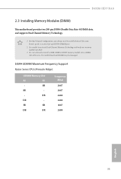
... this motherboard and DIMM may be damaged. SR SR DR DR Frequency (Mhz) 2667 2667 2400 2400 2667 2400 English 21 DR DR - B450M-HDV R4.0 2.3 Installing Memory Modules (DIMM) This motherboard provides two 288-pin DDR4 (Double Data Rate 4) DIMM slots, and supports Dual Channel Memory Technology. 1. ...It is not allowed to install a DDR, DDR2 or DDR3 memory module into a DDR4 slot; It is unable to install identical (the same brand, speed, size and chip-type) DDR4 DIMM pairs. 2.
... this motherboard and DIMM may be damaged. SR SR DR DR Frequency (Mhz) 2667 2667 2400 2400 2667 2400 English 21 DR DR - B450M-HDV R4.0 2.3 Installing Memory Modules (DIMM) This motherboard provides two 288-pin DDR4 (Double Data Rate 4) DIMM slots, and supports Dual Channel Memory Technology. 1. ...It is not allowed to install a DDR, DDR2 or DDR3 memory module into a DDR4 slot; It is unable to install identical (the same brand, speed, size and chip-type) DDR4 DIMM pairs. 2.

User Manual
Page 29
... expansion card and make sure that the power supply is switched off or the power cord is used for the card before you start the installation. Before installing an expansion card, please make necessary hardware settings for PCI Express x1 lane width cards. PCIe Slot Configurations Ryzen Series CPUs (Pinnacle Ridge) PCIE1...
... expansion card and make sure that the power supply is switched off or the power cord is used for the card before you start the installation. Before installing an expansion card, please make necessary hardware settings for PCI Express x1 lane width cards. PCIe Slot Configurations Ryzen Series CPUs (Pinnacle Ridge) PCIE1...
User Manual
Page 33
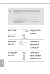
... ATXPWR1) (see p.6, No. 2) +12V CPU_FAN_SPEED This motherboard pro- E. B. To activate the front mic, go to the "FrontMic" Tab in our manual and chassis manual to install your system. 2. GND + 12V CHA_ FAN_SPEED CPU Fan Connector (4-pin CPU_FAN1) (see p.6, No. 4) 12 24 1 13 This motherboard provides a 24-pin ATX power connector. To...
... ATXPWR1) (see p.6, No. 2) +12V CPU_FAN_SPEED This motherboard pro- E. B. To activate the front mic, go to the "FrontMic" Tab in our manual and chassis manual to install your system. 2. GND + 12V CHA_ FAN_SPEED CPU Fan Connector (4-pin CPU_FAN1) (see p.6, No. 4) 12 24 1 13 This motherboard provides a 24-pin ATX power connector. To...

User Manual
Page 35
Nut Location PCB Length Module Type 1 A 4.2cm Type 2242 2 B 6cm Type2260 3 C 8cm Type 2280 English 30 Installing the M.2_SSD (NGFF) Module Step 1 Prepare a M.2_SSD (NGFF) module and the screw. 3 2 1 Step 2 Depending on the PCB type and length of your M.2_SSD (NGFF) ...module, find the corresponding nut location to replace mPCIe and mSATA. C B A No. 2.7 M.2_SSD (NGFF) Module Installation Guide The M.2, also known as the Next Generation Form Factor (NGFF), is a small size and versatile card edge connector that aims to be used. The...
Nut Location PCB Length Module Type 1 A 4.2cm Type 2242 2 B 6cm Type2260 3 C 8cm Type 2280 English 30 Installing the M.2_SSD (NGFF) Module Step 1 Prepare a M.2_SSD (NGFF) module and the screw. 3 2 1 Step 2 Depending on the PCB type and length of your M.2_SSD (NGFF) ...module, find the corresponding nut location to replace mPCIe and mSATA. C B A No. 2.7 M.2_SSD (NGFF) Module Installation Guide The M.2, also known as the Next Generation Form Factor (NGFF), is a small size and versatile card edge connector that aims to be used. The...


