RAID Installation Guide
Page 2
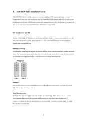
... the disk array management software will cause data damage or data loss. AMD BIOS RAID Installation Guide AMD BIOS RAID Installation Guide is called data mirroring that optimizes two identical hard disk drives to set . 1. WARNING!! It provides data protection and increases fault tolerance to RAID mode by using the onboard FastBuild BIOS utility under BIOS environment. After you to configure RAID functions by following the detailed instruction of the same model and capacity when creating a RAID set the option...
... the disk array management software will cause data damage or data loss. AMD BIOS RAID Installation Guide AMD BIOS RAID Installation Guide is called data mirroring that optimizes two identical hard disk drives to set . 1. WARNING!! It provides data protection and increases fault tolerance to RAID mode by using the onboard FastBuild BIOS utility under BIOS environment. After you to configure RAID functions by following the detailed instruction of the same model and capacity when creating a RAID set the option...
RAID Installation Guide
Page 8
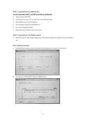
... boot, press or key to Tools Easy RAID Installer F. Insert the Support CD into one of the USB port. Go to enter UEFI setup utility. Click to finish the driver copy process. B. D. Follow instructions to find the driver inside your USB flash disk. Please download the "SATA Floppy Imaged driver" from ASRock's website A. B. A. Plug a USB drive into the DVD-ROM drive. During Windows installation process, when Disk selection page show up, please click . E. STEP 4: Windows installation A. Please install the DVD-ROM. STEP 3.1: Copy RAID driver to a USB flash...
... boot, press or key to Tools Easy RAID Installer F. Insert the Support CD into one of the USB port. Go to enter UEFI setup utility. Click to finish the driver copy process. B. D. Follow instructions to find the driver inside your USB flash disk. Please download the "SATA Floppy Imaged driver" from ASRock's website A. B. A. Plug a USB drive into the DVD-ROM drive. During Windows installation process, when Disk selection page show up, please click . E. STEP 4: Windows installation A. Please install the DVD-ROM. STEP 3.1: Copy RAID driver to a USB flash...
RAID Installation Guide
Page 12
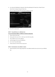
... to Tools Easy RAID Installer F. Go to exit. Please download the "SATA Floppy Imaged driver" from ASRock's website A. C. Plug a USB drive into the DVD-ROM drive. Please install the DVD-ROM. Follow instructions to enter UEFI setup utility. STEP 2.2: Download driver from ASRock's website and unzip the file into your USB flash disk. 12 During system boot, press or key to finish the driver copy process. D. A. Insert the Support CD into one of the USB port. STEP 2.1: Copy RAID driver to a USB flash drive You can choose either...
... to Tools Easy RAID Installer F. Go to exit. Please download the "SATA Floppy Imaged driver" from ASRock's website A. C. Plug a USB drive into the DVD-ROM drive. Please install the DVD-ROM. Follow instructions to enter UEFI setup utility. STEP 2.2: Download driver from ASRock's website and unzip the file into your USB flash disk. 12 During system boot, press or key to finish the driver copy process. D. A. Insert the Support CD into one of the USB port. STEP 2.1: Copy RAID driver to a USB flash drive You can choose either...
User Manual
Page 4
... Introduction 1 1.1 Package Contents 1 1.2 Specifications 2 1.3 Motherboard Layout 6 1.4 I/O Panel 8 Chapter 2 Installation 10 2.1 Installing the CPU 11 2.2 Installing the CPU Fan and Heatsink 13 2.3 Installing Memory Modules (DIMM) 21 2.4 Expansion Slots (PCI Express Slots) 24 2.5 Jumpers Setup 25 2.6 Onboard Headers and Connectors 26 2.7 M.2_SSD (NGFF) Module Installation Guide 30 Chapter 3 Software and Utilities Operation 34 3.1 Installing Drivers 34 3.2 A-Tuning 35 3.2.1 Installing A-Tuning 35 3.2.2 Using A-Tuning 35 3.3 ASRock Live Update & APP Shop 38...
... Introduction 1 1.1 Package Contents 1 1.2 Specifications 2 1.3 Motherboard Layout 6 1.4 I/O Panel 8 Chapter 2 Installation 10 2.1 Installing the CPU 11 2.2 Installing the CPU Fan and Heatsink 13 2.3 Installing Memory Modules (DIMM) 21 2.4 Expansion Slots (PCI Express Slots) 24 2.5 Jumpers Setup 25 2.6 Onboard Headers and Connectors 26 2.7 M.2_SSD (NGFF) Module Installation Guide 30 Chapter 3 Software and Utilities Operation 34 3.1 Installing Drivers 34 3.2 A-Tuning 35 3.2.1 Installing A-Tuning 35 3.2.2 Using A-Tuning 35 3.3 ASRock Live Update & APP Shop 38...
User Manual
Page 6
...-step installation guides. B450M-HDV R4.0 Chapter 1 Introduction Thank you require technical support related to quality and endurance. You may find the latest VGA cards and CPU support list on ASRock's website without notice. Chapter 4 contains the configuration guide of this manual occur, the updated version will be updated, the content of the BIOS setup. If you for M.2 Socket (Optional) • 1 x I/O Panel Shield 1 English Because the motherboard specifications and the BIOS software might be subject to change without...
...-step installation guides. B450M-HDV R4.0 Chapter 1 Introduction Thank you require technical support related to quality and endurance. You may find the latest VGA cards and CPU support list on ASRock's website without notice. Chapter 4 contains the configuration guide of this manual occur, the updated version will be updated, the content of the BIOS setup. If you for M.2 Socket (Optional) • 1 x I/O Panel Shield 1 English Because the motherboard specifications and the BIOS software might be subject to change without...
User Manual
Page 8
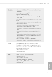
... (High Bit Rate Audio) with HDMI Port (Compliant HDMI monitor is required) • Supports HDCP with DVI-D and HDMI Ports • Supports 4K Ultra HD (UHD) playback with HDMI Port • 7.1 CH HD Audio (Realtek ALC887 Audio Codec) * To configure 7.1 CH HD Audio, it is required to 16GB. * The Max shared memory 16GB requires 32GB system memory installed. • Three graphics output options: D-Sub, DVI-D and HDMI • Supports Triple Monitor • Supports HDMI with max. B450M-HDV R4.0 Graphics Audio LAN • Integrated AMD RadeonTM...
... (High Bit Rate Audio) with HDMI Port (Compliant HDMI monitor is required) • Supports HDCP with DVI-D and HDMI Ports • Supports 4K Ultra HD (UHD) playback with HDMI Port • 7.1 CH HD Audio (Realtek ALC887 Audio Codec) * To configure 7.1 CH HD Audio, it is required to 16GB. * The Max shared memory 16GB requires 32GB system memory installed. • Three graphics output options: D-Sub, DVI-D and HDMI • Supports Triple Monitor • Supports HDMI with max. B450M-HDV R4.0 Graphics Audio LAN • Integrated AMD RadeonTM...
User Manual
Page 9
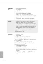
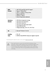
Rear Panel I/O • 1 x PS/2 Mouse/Keyboard Port • 1 x D-Sub Port • 1 x DVI-D Port • 1 x HDMI Port • 2 x USB 2.0 Ports (Supports ESD Protection) • 4 x USB 3.1 Gen1 Ports (Supports ESD Protection) • 1 x RJ-45 LAN Port with LED (ACT/LINK LED and SPEED LED) • HD Audio Jacks: Line in / Front Speaker / Microphone Storage • 4 x SATA3 6.0 Gb/s Connectors, support RAID (RAID 0, RAID 1 and RAID 10), NCQ, AHCI and Hot Plug • 1 x Ultra M.2 Socket, supports M Key type 2242/2260/2280 M.2 SATA3 6.0 Gb/s module and M.2 PCI Express module up to Gen3...
Rear Panel I/O • 1 x PS/2 Mouse/Keyboard Port • 1 x D-Sub Port • 1 x DVI-D Port • 1 x HDMI Port • 2 x USB 2.0 Ports (Supports ESD Protection) • 4 x USB 3.1 Gen1 Ports (Supports ESD Protection) • 1 x RJ-45 LAN Port with LED (ACT/LINK LED and SPEED LED) • HD Audio Jacks: Line in / Front Speaker / Microphone Storage • 4 x SATA3 6.0 Gb/s Connectors, support RAID (RAID 0, RAID 1 and RAID 10), NCQ, AHCI and Hot Plug • 1 x Ultra M.2 Socket, supports M Key type 2242/2260/2280 M.2 SATA3 6.0 Gb/s module and M.2 PCI Express module up to Gen3...
User Manual
Page 10
... damage caused by overclocking. English 5 B450M-HDV R4.0 BIOS Feature Hardware Monitor OS Certifications • AMI UEFI Legal BIOS with GUI support • Supports "Plug and Play" • ACPI 5.1 compliance wake up events • Supports jumperfree • SMBIOS 2.3 support • DRAM Voltage multi-adjustment • CPU/Chassis temperature sensing • CPU/Chassis Fan Tachometer • CPU/Chassis Quiet Fan • CPU/Chassis Fan multi-speed control • CASE OPEN detection • Voltage monitoring: +12V, +5V, +3.3V, Vcore • Microsoft® Windows® 10 64...
... damage caused by overclocking. English 5 B450M-HDV R4.0 BIOS Feature Hardware Monitor OS Certifications • AMI UEFI Legal BIOS with GUI support • Supports "Plug and Play" • ACPI 5.1 compliance wake up events • Supports jumperfree • SMBIOS 2.3 support • DRAM Voltage multi-adjustment • CPU/Chassis temperature sensing • CPU/Chassis Fan Tachometer • CPU/Chassis Quiet Fan • CPU/Chassis Fan multi-speed control • CASE OPEN detection • Voltage monitoring: +12V, +5V, +3.3V, Vcore • Microsoft® Windows® 10 64...
User Manual
Page 11
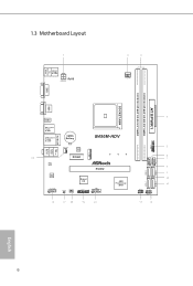
1.3 Motherboard Layout PS2 Keyboard/ Mouse USB 2.0 T: USB1 B: USB2 RoHS ATX12V CPU_FAN1 DDR4_A1 (64 bit, 288-FpinSBmo8d0ul0e) DDR4_A2 (64 bit, 288-pin module) USB3_5_6 ATXPWR1 SOCKET AM4 HDMI1 USB 3.1 Gen1 T: USB1 B: USB2 USB 3.1 Gen1 T: USB3 B: USB4 RJ-45 LAN CMOS Battery CHA_FAN1 BIOS ROM B450M-HDV Top: LINE IN Center: FRONT Bottom: MIC IN M2_1 19 PCIE1 LAN AUDIO CODEC HD_AUDIO1 1 CLRMOS1 1 CHA_FAN2 PCIE2 Super I/O TPMS1 1 1 COM1 AMD Promontory B450 16 1 SPK_CI1 1 PLED PWRBTN 1 HDLED RESET PANEL1 USB_3_4 USB_5_6 SATA3_3 SATA3_4 SATA3_1 SATA3_2 English 6
1.3 Motherboard Layout PS2 Keyboard/ Mouse USB 2.0 T: USB1 B: USB2 RoHS ATX12V CPU_FAN1 DDR4_A1 (64 bit, 288-FpinSBmo8d0ul0e) DDR4_A2 (64 bit, 288-pin module) USB3_5_6 ATXPWR1 SOCKET AM4 HDMI1 USB 3.1 Gen1 T: USB1 B: USB2 USB 3.1 Gen1 T: USB3 B: USB4 RJ-45 LAN CMOS Battery CHA_FAN1 BIOS ROM B450M-HDV Top: LINE IN Center: FRONT Bottom: MIC IN M2_1 19 PCIE1 LAN AUDIO CODEC HD_AUDIO1 1 CLRMOS1 1 CHA_FAN2 PCIE2 Super I/O TPMS1 1 1 COM1 AMD Promontory B450 16 1 SPK_CI1 1 PLED PWRBTN 1 HDLED RESET PANEL1 USB_3_4 USB_5_6 SATA3_3 SATA3_4 SATA3_1 SATA3_2 English 6
User Manual
Page 12
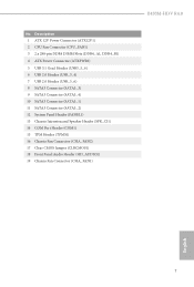
...2 CPU Fan Connector (CPU_FAN1) 3 2 x 288-pin DDR4 DIMM Slots (DDR4_A1, DDR4_B1) 4 ATX Power Connector (ATXPWR1) 5 USB 3.1 Gen1 Header (USB3_5_6) 6 USB 2.0 Header (USB_3_4) 7 USB 2.0 Header (USB_5_6) 8 SATA3 Connector (SATA3_3) 9 SATA3 Connector (SATA3_4) 10 SATA3 Connector (SATA3_1) 11 SATA3 Connector (SATA3_2) 12 System Panel Header (PANEL1) 13 Chassis Intrusion and Speaker Header (SPK_CI1) 14 COM Port Header (COM1) 15 TPM Header (TPMS1) 16 Chassis Fan Connector (CHA_FAN2) 17 Clear CMOS Jumper (CLRCMOS1) 18 Front Panel Audio Header (HD_AUDIO1) 19 Chassis Fan Connector (CHA_FAN1) B450M-HDV R4...
...2 CPU Fan Connector (CPU_FAN1) 3 2 x 288-pin DDR4 DIMM Slots (DDR4_A1, DDR4_B1) 4 ATX Power Connector (ATXPWR1) 5 USB 3.1 Gen1 Header (USB3_5_6) 6 USB 2.0 Header (USB_3_4) 7 USB 2.0 Header (USB_5_6) 8 SATA3 Connector (SATA3_3) 9 SATA3 Connector (SATA3_4) 10 SATA3 Connector (SATA3_1) 11 SATA3 Connector (SATA3_2) 12 System Panel Header (PANEL1) 13 Chassis Intrusion and Speaker Header (SPK_CI1) 14 COM Port Header (COM1) 15 TPM Header (TPMS1) 16 Chassis Fan Connector (CHA_FAN2) 17 Clear CMOS Jumper (CLRCMOS1) 18 Front Panel Audio Header (HD_AUDIO1) 19 Chassis Fan Connector (CHA_FAN1) B450M-HDV R4...
User Manual
Page 26
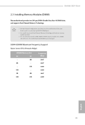
... Dual Channel Memory Technology with only one memory module installed. 3. It is not allowed to install a DDR, DDR2 or DDR3 memory module into a DDR4 slot; B450M-HDV R4.0 2.3 Installing Memory Modules (DIMM) This motherboard provides two 288-pin DDR4 (Double Data Rate 4) DIMM slots, and supports Dual Channel Memory Technology. 1. SR SR DR DR Frequency (Mhz) 2667 2667 2400 2400 2667 2400 English 21 It is unable to install identical (the same brand, speed, size and chip-type...
... Dual Channel Memory Technology with only one memory module installed. 3. It is not allowed to install a DDR, DDR2 or DDR3 memory module into a DDR4 slot; B450M-HDV R4.0 2.3 Installing Memory Modules (DIMM) This motherboard provides two 288-pin DDR4 (Double Data Rate 4) DIMM slots, and supports Dual Channel Memory Technology. 1. SR SR DR DR Frequency (Mhz) 2667 2667 2400 2400 2667 2400 English 21 It is unable to install identical (the same brand, speed, size and chip-type...
User Manual
Page 30
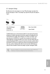
... down before you update the BIOS. Clear CMOS Jumper (CLRMOS1) (see p.6, No. 17) 2-pin Jumper Short: Clear CMOS Open: Default CLRMOS1 allows you clear the CMOS, the case open may be cleared only if the CMOS battery is "Short". Please remember toremove the jumper cap after you do not clear the CMOS right after clearing the CMOS. B450M-HDV R4.0 2.5 Jumpers Setup The illustration shows how jumpers are setup. Please be noted that the password, date, time, and user default profile will be...
... down before you update the BIOS. Clear CMOS Jumper (CLRMOS1) (see p.6, No. 17) 2-pin Jumper Short: Clear CMOS Open: Default CLRMOS1 allows you clear the CMOS, the case open may be cleared only if the CMOS battery is "Short". Please remember toremove the jumper cap after you do not clear the CMOS right after clearing the CMOS. B450M-HDV R4.0 2.5 Jumpers Setup The illustration shows how jumpers are setup. Please be noted that the password, date, time, and user default profile will be...
User Manual
Page 32
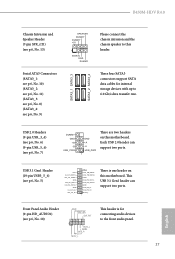
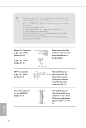
... SATA3 connectors support SATA data cables for connecting audio devices to 6.0 Gb/s data transfer rate. Front Panel Audio Header (9-pin HD_AUDIO1) (see p.6, No. 5) Vbus IntA_PA_SSRXIntA_PA_SSRX+ GND IntA_PA_SSTXIntA_PA_SSTX+ GND IntA_PA_DIntA_PA_D+ Vbus IntA_PB_SSRXIntA_PB_SSRX+ GND IntA_PB_SSTXIntA_PB_SSTX+ GND IntA_PB_DIntA_PB_D+ Dummy 1 There is for internal storage devices with up to the front audio panel. 27 English This USB 3.1 Gen1 header can support two ports. B450M-HDV R4.0 Chassis Intrusion and Speaker Header (7-pin SPK_CI1) (see p.6, No. 13) Serial ATA3 Connectors...
... SATA3 connectors support SATA data cables for connecting audio devices to 6.0 Gb/s data transfer rate. Front Panel Audio Header (9-pin HD_AUDIO1) (see p.6, No. 5) Vbus IntA_PA_SSRXIntA_PA_SSRX+ GND IntA_PA_SSTXIntA_PA_SSTX+ GND IntA_PA_DIntA_PA_D+ Vbus IntA_PB_SSRXIntA_PB_SSRX+ GND IntA_PB_SSTXIntA_PB_SSTX+ GND IntA_PB_DIntA_PB_D+ Dummy 1 There is for internal storage devices with up to the front audio panel. 27 English This USB 3.1 Gen1 header can support two ports. B450M-HDV R4.0 Chassis Intrusion and Speaker Header (7-pin SPK_CI1) (see p.6, No. 13) Serial ATA3 Connectors...
User Manual
Page 33
... the instructions in the Realtek Control panel and adjust "Recording Volume". Connect Ground (GND) to function correctly. E. 1. GND + 12V CHA_ FAN_SPEED CPU Fan Connector (4-pin CPU_FAN1) (see p.6, No. 4) 12 24 1 13 This motherboard provides a 24-pin ATX power connector. GND FAN_SPEED_CONTROL vides a 4-Pin CPU fan 1 2 3 4 (Quiet Fan) connector. To use an AC'97 audio panel, please install it along Pin 1 and Pin 13. English 28 High Definition Audio supports Jack Sensing, but the panel wire on the chassis must support HDA...
... the instructions in the Realtek Control panel and adjust "Recording Volume". Connect Ground (GND) to function correctly. E. 1. GND + 12V CHA_ FAN_SPEED CPU Fan Connector (4-pin CPU_FAN1) (see p.6, No. 4) 12 24 1 13 This motherboard provides a 24-pin ATX power connector. GND FAN_SPEED_CONTROL vides a 4-Pin CPU fan 1 2 3 4 (Quiet Fan) connector. To use an AC'97 audio panel, please install it along Pin 1 and Pin 13. English 28 High Definition Audio supports Jack Sensing, but the panel wire on the chassis must support HDA...
User Manual
Page 39
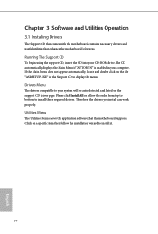
Drivers Menu The drivers compatible to display the menu. Running The Support CD To begin using the support CD, insert the CD into your computer. If the Main Menu does not appear automatically, locate and double click on the file "ASRSETUP.EXE" in your CD-ROM drive. Click on the support CD driver page. Utilities Menu The Utilities Menu shows the application software that enhance the motherboard's features. Therefore, the drivers you install can work properly. Chapter...
Drivers Menu The drivers compatible to display the menu. Running The Support CD To begin using the support CD, insert the CD into your computer. If the Main Menu does not appear automatically, locate and double click on the file "ASRSETUP.EXE" in your CD-ROM drive. Click on the support CD driver page. Utilities Menu The Utilities Menu shows the application software that enhance the motherboard's features. Therefore, the drivers you install can work properly. Chapter...
User Manual
Page 55
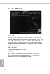
... or power supplies. AMD fTPM Switch Use this function may reduce CPU voltage and memory frequency, and lead to enable or disable AMD CPU fTPM. Please set this item to [Disable] if above issue occurs. If you install Windows® OS and want to enable this function, please set to enable or disable AMD's Cool 'n' QuietTM technology. The default value is set this item to [Enabled]. Configuration options: [Enabled] and [Disabled]. SVM Mode When this item to [Enabled], a VMM (Virtual Machine Architecture) can utilize...
... or power supplies. AMD fTPM Switch Use this function may reduce CPU voltage and memory frequency, and lead to enable or disable AMD CPU fTPM. Please set this item to [Disable] if above issue occurs. If you install Windows® OS and want to enable this function, please set to enable or disable AMD's Cool 'n' QuietTM technology. The default value is set this item to [Enabled]. Configuration options: [Enabled] and [Disabled]. SVM Mode When this item to [Enabled], a VMM (Virtual Machine Architecture) can utilize...
User Manual
Page 59
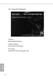
Serial Port Address Select the address of the Serial port. 4.4.5 Super IO Configuration Serial Port Enable or disable the Serial port. PS2 Y-Cable Enable the PS2 Y-Cable or set this option to Auto. 54 English
Serial Port Address Select the address of the Serial port. 4.4.5 Super IO Configuration Serial Port Enable or disable the Serial port. PS2 Y-Cable Enable the PS2 Y-Cable or set this option to Auto. 54 English
User Manual
Page 63
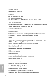
... error Controls DF::PIEConfig[DisImmSyncFloodOnFatalError] Disabling this option sets DF:PIEConfig[DisImmSyncFloodOnFatalError]. 58 English To re-enable SMT, a POWER CYCLE is disabled. Streaming Stores Control Enables or disables the streaming stores functionality. Once this field are from 0x1 (1) - 0x10 (16). SMTEN This item can be used to be used to remove any cores, a POWER CYCLE is the number of cores to disable symmetric multithreading. Warning: S3 is NOT SUPPORTED...
... error Controls DF::PIEConfig[DisImmSyncFloodOnFatalError] Disabling this option sets DF:PIEConfig[DisImmSyncFloodOnFatalError]. 58 English To re-enable SMT, a POWER CYCLE is disabled. Streaming Stores Control Enables or disables the streaming stores functionality. Once this field are from 0x1 (1) - 0x10 (16). SMTEN This item can be used to be used to remove any cores, a POWER CYCLE is the number of cores to disable symmetric multithreading. Warning: S3 is NOT SUPPORTED...
User Manual
Page 64
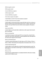
... field should not be ignored if the memory doesn't support the selected option. Memory Clear When this option's setting. Note that distributed requires memory on parts where the probe filter is enabled. System probe filter Controls whether or not the probe filter is fuse disabled. Channel interleaving hash Controls whether or not the address bits are hashed during channel interleave mode. Note that it will always be...
... field should not be ignored if the memory doesn't support the selected option. Memory Clear When this option's setting. Note that distributed requires memory on parts where the probe filter is enabled. System probe filter Controls whether or not the probe filter is fuse disabled. Channel interleaving hash Controls whether or not the address bits are hashed during channel interleave mode. Note that it will always be...
User Manual
Page 72
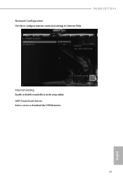
Network Configuration Use this to download the UEFI firmware. B450M-HDV R4.0 Internet Setting Enable or disable sound effects in the setup utility. English 67 UEFI Download Server Select a server to configure internet connection settings for Internet Flash.
Network Configuration Use this to download the UEFI firmware. B450M-HDV R4.0 Internet Setting Enable or disable sound effects in the setup utility. English 67 UEFI Download Server Select a server to configure internet connection settings for Internet Flash.


