Intel Rapid Storage Guide
Page 6
Click the "Create" icon to create a RAID array. Create a RAID Array 1. Click "Next". 6 Here we take RAID 1 for example. 3. In "Select Volume Type", click "Real-time data protection (RAID 1)". Double-click "Intel Rapid Storage Technology" icon, then below main screen appears. 2.
Click the "Create" icon to create a RAID array. Create a RAID Array 1. Click "Next". 6 Here we take RAID 1 for example. 3. In "Select Volume Type", click "Real-time data protection (RAID 1)". Double-click "Intel Rapid Storage Technology" icon, then below main screen appears. 2.
Quick Installation Guide
Page 21
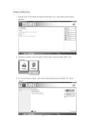
... caps over these headers and connectors. You may differ by chassis. The LED is on the chassis front panel. A front panel module mainly consists of power switch, reset switch, power LED, hard drive activity LED, speaker and etc. RESET (Reset Switch): Connect to this ...will cause permanent damage to perform a normal restart. PWRBTN (Power Switch): Connect to the hard drive activity LED on the chassis front panel. B365M Pro4-F 2.6 Onboard Headers and Connectors Onboard headers and connectors are matched correctly. The LED is off (S5). HDLED (Hard Drive Activity LED): Connect...
... caps over these headers and connectors. You may differ by chassis. The LED is on the chassis front panel. A front panel module mainly consists of power switch, reset switch, power LED, hard drive activity LED, speaker and etc. RESET (Reset Switch): Connect to this ...will cause permanent damage to perform a normal restart. PWRBTN (Power Switch): Connect to the hard drive activity LED on the chassis front panel. B365M Pro4-F 2.6 Onboard Headers and Connectors Onboard headers and connectors are matched correctly. The LED is off (S5). HDLED (Hard Drive Activity LED): Connect...
User Manual
Page 5
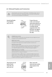
3.3.3 BIOS & Drivers 34 3.3.4 Setting 38 Chapter 4 UEFI SETUP UTILITY 39 4.1 Introduction 39 4.2 EZ Mode 40 4.3 Advanced Mode 41 4.3.1 UEFI Menu Bar 41 4.3.2 Navigation Keys 42 4.4 Main Screen 43 4.5 OC Tweaker Screen 44 4.6 Advanced Screen 54 4.6.1 CPU Configuration 55 4.6.2 Chipset Configuration 67 4.6.3 Storage Configuration 60 4.6.4 Super IO Configuration 61 4.6.5 ACPI Configuration 62 4.6.6 ...
3.3.3 BIOS & Drivers 34 3.3.4 Setting 38 Chapter 4 UEFI SETUP UTILITY 39 4.1 Introduction 39 4.2 EZ Mode 40 4.3 Advanced Mode 41 4.3.1 UEFI Menu Bar 41 4.3.2 Navigation Keys 42 4.4 Main Screen 43 4.5 OC Tweaker Screen 44 4.6 Advanced Screen 54 4.6.1 CPU Configuration 55 4.6.2 Chipset Configuration 67 4.6.3 Storage Configuration 60 4.6.4 Super IO Configuration 61 4.6.5 ACPI Configuration 62 4.6.6 ...

User Manual
Page 25
... GND DUMMY Please connect the chassis intrusion and the chassis speaker to the hard drive activity LED on the chassis front panel. A front panel module mainly consists of power switch, reset switch, power LED, hard drive activity LED, speaker and etc. PLED (System Power LED): Connect to the power status indicator... status indicator on the chassis front panel. Do NOT place jumper caps over the headers and connectors will cause permanent damage to perform a normal restart. B365M Pro4-F 2.6 Onboard Headers and Connectors Onboard headers and connectors are matched correctly.
... GND DUMMY Please connect the chassis intrusion and the chassis speaker to the hard drive activity LED on the chassis front panel. A front panel module mainly consists of power switch, reset switch, power LED, hard drive activity LED, speaker and etc. PLED (System Power LED): Connect to the power status indicator... status indicator on the chassis front panel. Do NOT place jumper caps over the headers and connectors will cause permanent damage to perform a normal restart. B365M Pro4-F 2.6 Onboard Headers and Connectors Onboard headers and connectors are matched correctly.
User Manual
Page 35
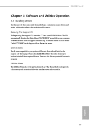
...the file "ASRSETUP.EXE" in your system will be auto-detected and listed on the support CD driver page. If the Main Menu does not appear automatically, locate and double click on a specific item then follow the order from top to bottom to...Main Menu if "AUTORUN" is enabled in the Support CD to install those required drivers. Please click Install All or follow the installation wizard to your computer. Utilities Menu The Utilities Menu shows the application software that enhance the motherboard's features. Drivers Menu The drivers compatible to install it. 29 English B365M Pro4...
...the file "ASRSETUP.EXE" in your system will be auto-detected and listed on the support CD driver page. If the Main Menu does not appear automatically, locate and double click on a specific item then follow the order from top to bottom to...Main Menu if "AUTORUN" is enabled in the Support CD to install those required drivers. Please click Install All or follow the installation wizard to your computer. Utilities Menu The Utilities Menu shows the application software that enhance the motherboard's features. Drivers Menu The drivers compatible to install it. 29 English B365M Pro4...
User Manual
Page 36
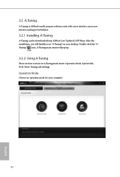
3.2 A-Tuning A-Tuning is ASRock's multi purpose software suite with a new interface, more new features and improved utilities. 3.2.1 Installing A-Tuning A-Tuning can be downloaded from ASRock Live Update & APP Shop. After the installation, you will pop up. 3.2.2 Using A-Tuning There are four sections in A-Tuning main menu: Operation Mode, System Info, FAN-Tastic Tuning and Settings. Double-click the "ATuning" icon, A-Tuning main menu will find the icon "A-Tuning" on your computer. 30 English Operation Mode Choose an operation mode for your desktop.
3.2 A-Tuning A-Tuning is ASRock's multi purpose software suite with a new interface, more new features and improved utilities. 3.2.1 Installing A-Tuning A-Tuning can be downloaded from ASRock Live Update & APP Shop. After the installation, you will pop up. 3.2.2 Using A-Tuning There are four sections in A-Tuning main menu: Operation Mode, System Info, FAN-Tastic Tuning and Settings. Double-click the "ATuning" icon, A-Tuning main menu will find the icon "A-Tuning" on your computer. 30 English Operation Mode Choose an operation mode for your desktop.
User Manual
Page 47
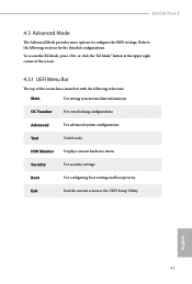
... the screen has a menu bar with the following sections for the detailed configurations. Refer to configure the BIOS settings. B365M Pro4-F 4.3 Advanced Mode The Advanced Mode provides more options to the following selections: Main For setting system time/date information OC Tweaker For overclocking configurations Advanced For advanced system configurations Tool Useful tools...
... the screen has a menu bar with the following sections for the detailed configurations. Refer to configure the BIOS settings. B365M Pro4-F 4.3 Advanced Mode The Advanced Mode provides more options to the following selections: Main For setting system time/date information OC Tweaker For overclocking configurations Advanced For advanced system configurations Tool Useful tools...
User Manual
Page 49
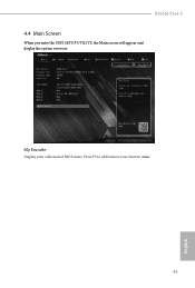
My Favorite Display your collection of BIOS items. Press F5 to add/remove your favorite items. 43 English B365M Pro4-F 4.4 Main Screen When you enter the UEFI SETUP UTILITY, the Main screen will appear and display the system overview.
My Favorite Display your collection of BIOS items. Press F5 to add/remove your favorite items. 43 English B365M Pro4-F 4.4 Main Screen When you enter the UEFI SETUP UTILITY, the Main screen will appear and display the system overview.
